
The rapid advancement of science and technology has led to the increasingly widespread application of backup power systems. Both DC power supply systems and AC uninterruptible power supply systems require batteries as a backup power source. When utility power is normal, the battery stores electrical energy in the rectifier-charging circuit and also serves to smooth filtering and suppress noise in the DC circuit. Upon a utility power failure, the system immediately switches to battery power to ensure uninterrupted supply.
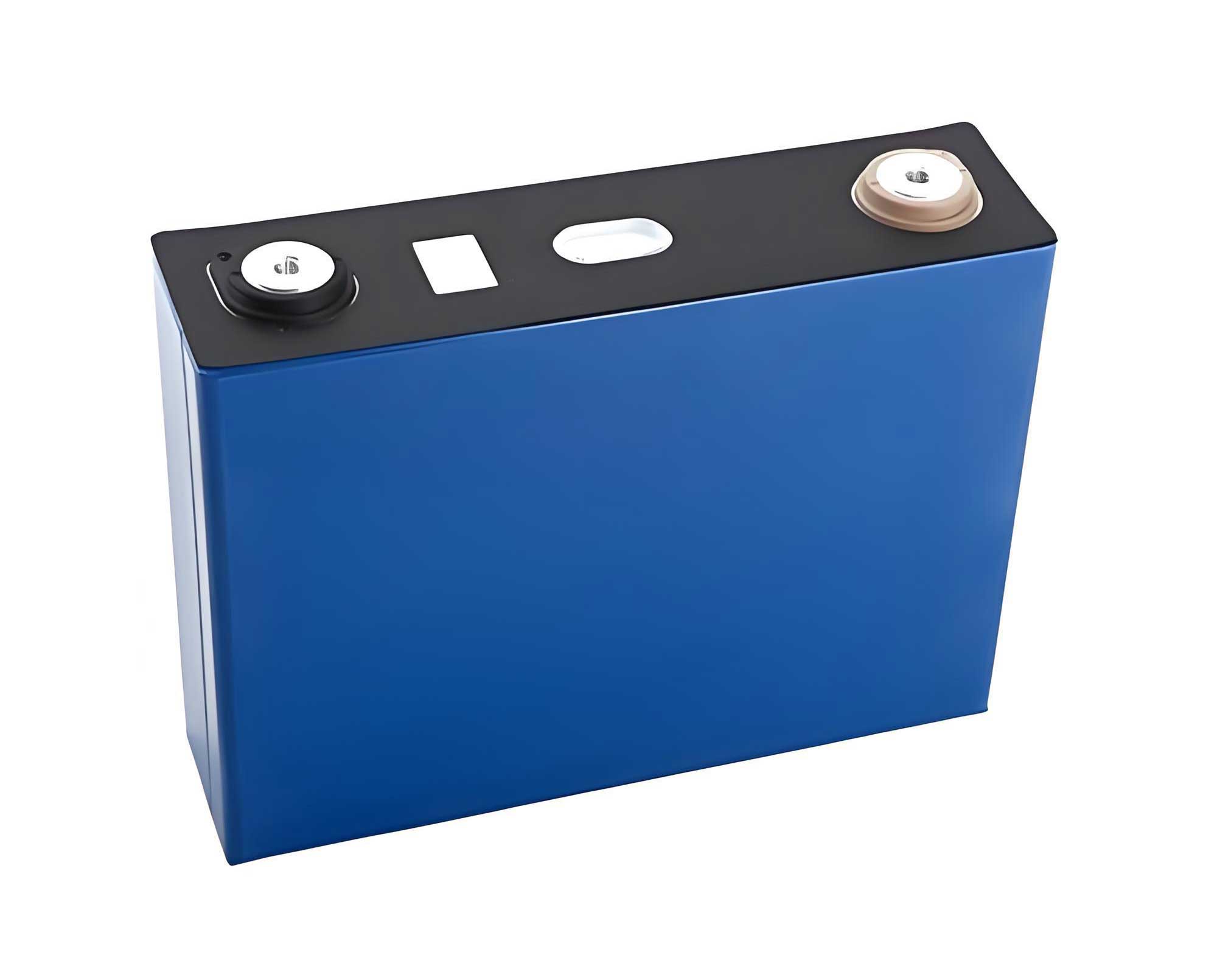
For a long time, lead-acid batteries have been the preferred choice for backup power due to their low cost, mature technology, and abundant specifications. However, lead-acid batteries suffer from shortcomings such as short service life, heavy weight, large footprint, frequent daily maintenance, high maintenance workload, and environmental unfriendliness, leading to a gradual decline in their development. With the rapid development of China’s battery industry, various new types of energy storage batteries continue to emerge. Among the many types of energy storage batteries, the LiFePO4 battery, characterized by its flexible grouping, high energy density, good safety performance, high energy storage efficiency, long service life, moderate cost, and convenient maintenance, has gradually replaced lead-acid batteries under policy-driven and market-selected conditions and is being increasingly widely used in the backup power field. However, due to the limitations of lithium-ion battery technology, to meet the application requirements of backup power, it is necessary to connect batteries in series to achieve a certain voltage level and then in parallel to meet capacity requirements. This study takes a 217.6V, 100Ah LiFePO4 battery pack system as the research object to investigate the circulating currents and current imbalances generated among various branches when such systems are connected in parallel.
Introduction
Parallel connection of battery packs is a common method to increase system capacity and current output in applications ranging from electric vehicles to large-scale energy storage. For LiFePO4 battery systems, understanding the electrical behavior during parallel operation is critical for ensuring system safety, reliability, and longevity. Key concerns include the initial inrush or circulating currents that flow between packs when connected with different voltages or States of Charge (SOC), and the current distribution (current imbalance) during subsequent charging and discharging cycles. These phenomena are primarily governed by the voltage difference at the connection instant and the internal resistance of each branch. Excessive circulating currents can stress battery management system (BMS) components and the cells themselves, while persistent current imbalance can lead to uneven aging. This paper presents an experimental investigation into these behaviors for identical 217.6V LiFePO4 battery pack systems under float charging conditions and during standard charge-discharge cycles.
1. Experimental Setup and Parameters
The equipment and parameters used in this experiment are as follows: Hubei Depu Electric Co., Ltd. BTS2000-750V/2*200A power battery pack comprehensive test equipment, FLUKE digital multimeter, CANalyzer Pro bus analyzer, and Thinkpad laptop.
2. Test Objects
The test objects are two sets of 217.6V, 100Ah LiFePO4 battery pack systems, numbered System 1 and System 2. The individual cells within both systems are selected from the same grade of 3.2V, 100Ah laminated aluminum shell square LiFePO4 batteries. The basic performance parameters of the battery pack system are shown in Table 1. The wiring configuration for the parallel battery pack system is illustrated in the following diagram (conceptual).
| Serial Number | Item | Technical Specification |
|---|---|---|
| 1 | Nominal Voltage | 217.6 V |
| 2 | Rated Capacity | 100 Ah |
| 3 | Maximum Charge Current | 100 A |
| 4 | Maximum Discharge Current | 200 A |
| 5 | Operating Voltage Range | 183.6 V ~ 234.6 V |
| 6 | Equalization Charge Voltage | 234.6 V |
| 7 | Float Charge Voltage | 231.2 V |
| 8 | Configuration | 68 series, 1 parallel (68S1P) |
3. Experimental Methodology
The experimental methodology was structured into three distinct phases to characterize the system’s behavior comprehensively.
Phase 1: DC Internal Resistance Measurement. The DC internal resistance of each LiFePO4 battery pack branch was determined according to the method specified in IEC 62620. The test was conducted at (25 ± 2)°C. The battery pack system was first fully charged, then discharged at a constant current of 0.5 It A (where It = 100A) for 1 hour. Subsequently, it was discharged at a constant current I1 = 0.2 It A for 30 seconds, and the terminal voltage U1 at the end of this period was measured. Immediately after, the discharge current was increased to I2 = 1.0 It A and maintained for 5 seconds, and the terminal voltage U2 at the end was measured. The DC internal resistance R_dc was calculated using the formula:
$$ R_{dc} = \frac{U_1 – U_2}{I_2 – I_1} $$
This process established the baseline internal resistance and confirmed the similarity between the two LiFePO4 battery pack systems.
Phase 2: Parallel Connection with Different SOC under Float Charge. This phase investigated the circulating current upon connection. System 1 was maintained in a float charge state (with the charging device current-limited to 0.2It A). System 2 was preconditioned to different SOC levels: 100%, 95%, 90%, 80%, and 70%. At each SOC level, System 2 was connected in parallel with System 1. The voltage and current transients for both LiFePO4 battery pack systems were recorded to determine the magnitude and duration of the circulating current.
Phase 3: Parallel Charge-Discharge Cycle Test. This phase evaluated current distribution during normal operation. First, System 1 and System 2 were individually fully charged and then individually discharged at 0.5It A to a minimum cell voltage of 2.5 V to establish their standalone capacities. Subsequently, the two systems were connected in parallel. The parallel assembly was charged with a constant current of 0.5 It A until the total voltage reached 231.2 V, at which point it switched to constant voltage charging until the current decreased to 0.05 It A. Finally, the parallel system was discharged at a constant current of 0.5 It A to the minimum cell voltage of 2.5 V. The current in each branch was monitored throughout to assess the current imbalance during the charge and discharge processes.
4. Test Results and Analysis
4.1 DC Internal Resistance Test Results
The voltage and current curves during the DC internal resistance test for both LiFePO4 battery pack systems are shown in the respective figures (conceptually described). For System 1, the voltages were U1= 222.8 V and U2= 219.5 V. Applying the formula:
$$ R_{dc,1} = \frac{222.8\,V – 219.5\,V}{100\,A – 20\,A} = \frac{3.3\,V}{80\,A} = 0.04125\, \Omega = 41.25\,m\Omega $$
For System 2, the measured voltages were identical: U1= 222.8 V and U2= 219.5 V, yielding the same result:
$$ R_{dc,2} = \frac{222.8\,V – 219.5\,V}{100\,A – 20\,A} = 41.25\,m\Omega $$
This confirms that the DC internal resistances of the two LiFePO4 battery pack systems were identical at the beginning of the parallel tests, providing a controlled baseline.
4.2 Parallel Connection Test Results with Different SOC
The results from connecting LiFePO4 battery pack systems with varying SOC differences are summarized below. The key parameters are the voltage difference at the moment of connection, the peak circulating current, and its duration.
| SOC Difference | Voltage Difference (V) | Peak Output Current from System 1 (A) | Peak Input Current to System 2 (A) | Circulation Duration (s) |
|---|---|---|---|---|
| 0% | 0.4 | 4.5 | 4.5 | 107 |
| 5% | 5.3 | 46.9 | 46.3 | 139 |
| 10% | 6.2 | 50.1 | 50.4 | 93 |
| 20% | 5.4 | 47.9 | 46.0 | 172 |
| 30% | 5.4 | 47.0 | 49.8 | 223 |
Analysis: For two LiFePO4 battery pack systems with identical DC internal resistance connected in parallel, the peak circulating current is primarily determined by the instantaneous voltage difference between their terminals, as described by Ohm’s law for the loop: $I_{circ} \approx \Delta V / (R_{int,1} + R_{int,2})$. Within the 70% to 100% SOC range, the open-circuit voltage (OCV) curve of LiFePO4 chemistry is notably flat. This means that even significant SOC differences result in relatively modest voltage differences. Consequently, the SOC difference itself has a limited direct impact on the peak circulating current magnitude. The data in Table 2 supports this: a 0.4V difference caused a 4.5A peak, while differences around 5.3-6.2V caused peaks of approximately 47-50A. The peak current correlates more strongly with the voltage difference than with the SOC percentage difference.
4.3 Parallel Charge-Discharge Test Results and Analysis
The standalone discharge capacities of System 1 and System 2 at 0.5It A were 102.24 Ah and 102.14 Ah, respectively. The voltage and current curves for each branch during the parallel charge and discharge cycle are shown in the corresponding figures.
Current Distribution Dynamics: During both parallel charging and discharging, the two branches continuously adjusted their current sharing to maintain voltage equilibrium across the parallel connection. The process can be described in phases:
- Initial Phase: Due to initial voltage mismatch (from the prior standalone discharge), current distribution was unequal. The branch with the higher terminal voltage (lower internal voltage drop) accepted more charging current or delivered more discharging current.
- Mid Phase: As the charging/discharging progressed, the voltages of the two LiFePO4 battery pack systems converged, leading to a reduction and eventual crossing of the branch currents as they tended towards balance.
- Final Phase: Towards the end of the charge/discharge cycle, particularly near voltage cut-off points, the voltage change rate increases, causing the current imbalance to widen again as one pack reaches its limits slightly before the other.
System Capacity: The total discharge capacity of the parallel-connected LiFePO4 battery system was measured to be 204.44 Ah. This value is essentially equal to the sum of the individual capacities (102.24 Ah + 102.14 Ah = 204.38 Ah). This confirms that within the scope of this test, connecting these LiFePO4 battery packs in parallel did not lead to a loss of usable capacity; each branch was able to achieve full charge and complete discharge during system operation.
5. Discussion and Implications
The findings of this study on LiFePO4 battery pack systems have several practical implications. The direct relationship between voltage difference and inrush current highlights the importance of voltage synchronization prior to connecting packs in parallel. For systems employing a flat-voltage chemistry like LiFePO4, even modest voltage synchronization can prevent high circulating currents. The observed dynamic current sharing during operation is a natural consequence of the system seeking a common bus voltage. With well-matched internal resistances, as in this test, the current imbalance is transient and self-correcting, allowing for effective capacity utilization. These properties make LiFePO4 battery systems well-suited for parallel configurations in backup power applications, provided connection protocols are followed. The ability to sum capacities linearly is a key advantage for scalable system design.
However, it is crucial to acknowledge the limitations of this study. The experiments were conducted on new LiFePO4 battery packs with identical internal resistances. Real-world applications involve packs with varying degrees of aging, which increases internal resistance and can lead to capacity fade. The impact of DC internal resistance mismatch was not investigated here. Furthermore, the study was limited to a two-branch parallel configuration and a specific SOC range (70-100%).
Future research should expand upon these foundations to develop more robust design and operation guidelines for parallel LiFePO4 battery systems:
- Investigating the impact of intentional and aged-based internal resistance mismatches on steady-state current imbalance and long-term aging divergence.
- Examining parallel connection behavior over the entire SOC range, especially the steeper voltage regions at low SOC.
- Studying the behavior of three or more LiFePO4 battery pack systems in parallel to understand scalability and more complex interactions.
- Developing and validating standardized safety protocols and connection sequences for paralleling battery systems in field applications.
- Modeling the combined effects of SOC difference, internal resistance, and aging on circulating current and balance.
6. Conclusion
Based on the experimental work conducted, the following conclusions can be drawn regarding the parallel operation of the tested 217.6V LiFePO4 battery pack systems:
- For two LiFePO4 battery pack systems with identical DC internal resistance, the peak circulating current upon connection is primarily determined by the terminal voltage difference at the instant of paralleling. Within the 70% to 100% SOC range, the SOC difference has a limited direct effect on the peak current due to the flat OCV-SOC characteristic of the LiFePO4 chemistry.
- During parallel charging and discharging, the current distribution between the branches is dynamic. The system self-regulates, with branches adjusting their current contribution or absorption to maintain a common bus voltage, leading to phases of imbalance and convergence.
- The total discharge capacity of the parallel-connected LiFePO4 battery system is equal to the sum of the capacities of the individual branches when discharged separately, indicating no inherent capacity loss due to the parallel connection under these matched conditions.
- When connected in parallel, each branch of the LiFePO4 battery system is capable of being fully charged and fully discharged within the operational cycle of the combined system.
In summary, parallel operation of well-matched LiFePO4 battery pack systems is feasible and effective, with the initial voltage difference being the critical parameter to manage for safe connection. The systems demonstrate inherent self-balancing tendencies during operation, ensuring full capacity utilization. These findings provide a foundational understanding for the design and deployment of parallel LiFePO4 battery systems in backup power and other energy storage applications.