
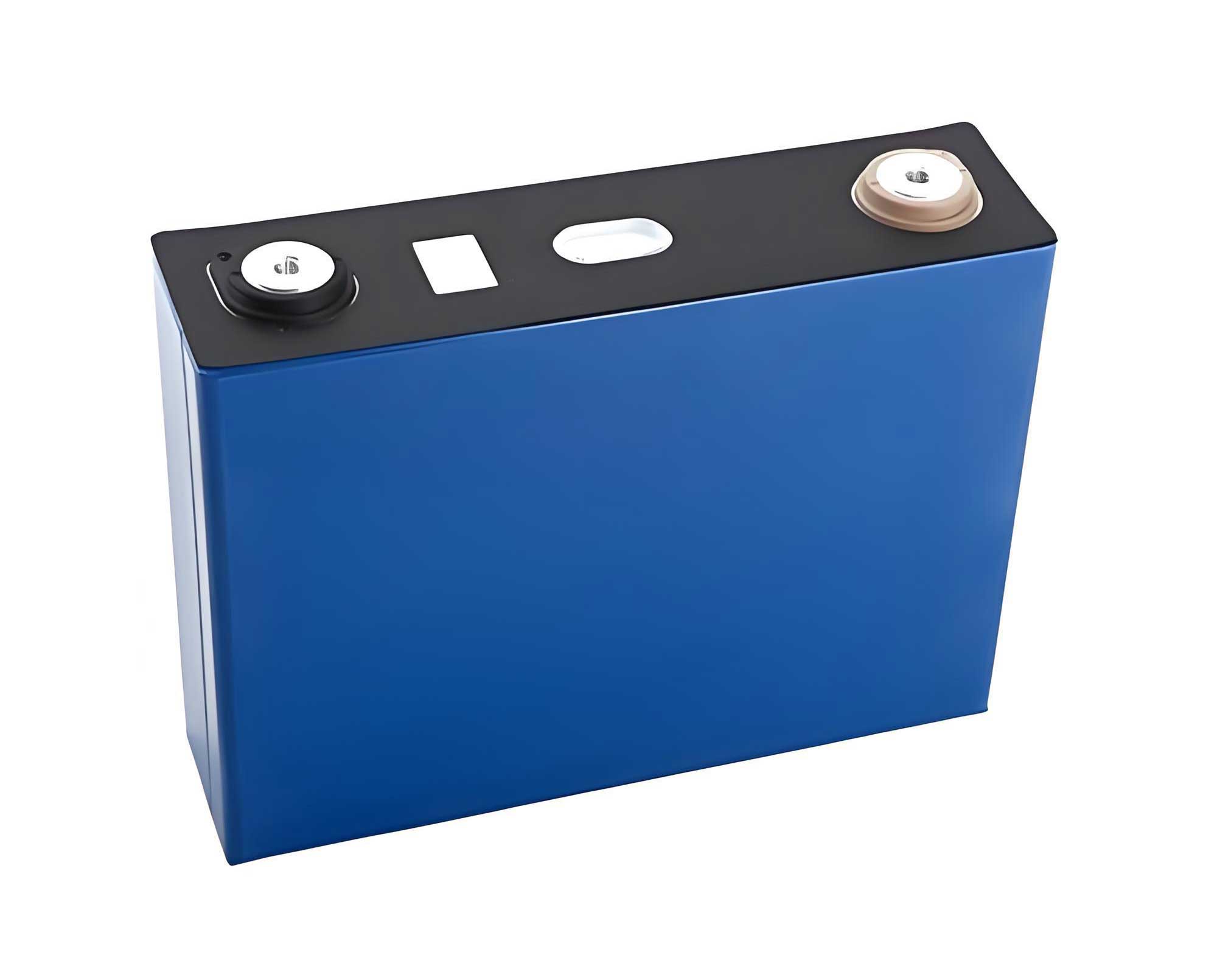
In the realm of energy storage systems, lithium iron phosphate (LiFePO4) batteries have emerged as a cornerstone technology due to their exceptional safety profile, long cycle life, high energy density, and superior thermal stability. As a researcher deeply involved in power electronics and battery management, I have focused on addressing one of the most persistent challenges in deploying LiFePO4 battery packs: state-of-charge (SOC) imbalance among individual cells. This imbalance, arising from manufacturing variances, differential aging, temperature gradients, and uneven charge-discharge rates, severely compromises the overall pack capacity, accelerates degradation, and poses safety risks. Therefore, developing efficient and reliable battery balancing techniques is paramount for optimizing the performance and longevity of LiFePO4 battery systems.
Battery balancing methods are broadly categorized into passive (dissipative) and active (non-dissipative) techniques. Passive balancing, often implemented using shunt resistors, dissipates excess energy from higher-SOC cells as heat. While simple and cost-effective, this method is inherently inefficient, leads to thermal management issues, and prolongs balancing time. Active balancing, in contrast, redistributes energy among cells using power electronic converters, thereby minimizing energy loss. Common active topologies include capacitor-based, transformer-based, and inductor-based systems. Among these, inductor-based balancing, particularly leveraging Buck-Boost converter principles, offers significant advantages in terms of control flexibility, current handling capability, and potential for high-speed energy transfer. This paper presents a comprehensive study on an improved inductor-based bidirectional balancing circuit and its associated control strategy, specifically designed for LiFePO4 battery packs. The proposed system enhances balancing efficiency and speed without increasing hardware complexity, validated through detailed simulation under both static and dynamic conditions.
The core of the proposed system is an enhanced bidirectional inductive balancing circuit derived from the classic Buck-Boost converter topology. For a LiFePO4 battery pack comprising n series-connected cells, the circuit employs n-1 balancing modules, each interfacing between adjacent cells or cell groups. A fundamental module between two cells, Celli and Celli+1, consists of a switching MOSFET (Mi-1), a freewheeling diode (Di-2), an energy-transfer inductor (Li), and a small damping resistor parallel to the inductor to suppress LC oscillations. The operational principle for transferring energy from a higher-SOC cell (e.g., Celli) to a lower-SOC cell (e.g., Celli+1) involves three distinct phases within each high-frequency switching cycle:
- Inductor Charging Phase: Switch Mi-1 is turned ON. Current builds up linearly in inductor Li, storing energy from Celli. The peak inductor current IL,peak is governed by the cell voltage Vi, inductance L, and the switch ON-time ton:
$$ I_{L,peak} = \frac{V_i}{L} t_{on} $$ - Energy Transfer Phase: Switch Mi-1 is turned OFF. The stored energy in Li is released through diode Di-2 to charge Celli+1. The current decays linearly, transferring charge.
- Inductor Reset Phase: To prevent magnetic saturation and ensure operation in Discontinuous Conduction Mode (DCM), the switching duty cycle is controlled such that the inductor current reaches zero before the next cycle begins. The condition for DCM is:
$$ t_{on} + t_{off} < T_{sw} $$
where Tsw is the switching period, and toff is the time for current decay.
The key innovation in the improved circuit lies in its modular and scalable architecture, which facilitates simultaneous intra-segment and inter-segment balancing. For large LiFePO4 battery packs, cells are logically grouped into segments. Within each segment, adjacent cell-to-cell balancing occurs (intra-segment). Simultaneously, the entire segment can be treated as a “macro-cell,” and energy can be transferred between segments (inter-segment) using designated balancing modules that interface between segment boundaries. This hierarchical approach dramatically reduces the longest energy transfer path, thereby accelerating the overall balancing process. The table below summarizes the comparative advantages of different balancing topologies for LiFePO4 battery systems.
| Balancing Topology | Energy Efficiency | Balancing Speed | Circuit Complexity | Cost | Suitability for LiFePO4 Packs |
|---|---|---|---|---|---|
| Passive (Resistive) | Low (<50%) | Slow | Low | Low | Low-power, cost-sensitive |
| Active Capacitive | Medium (70-85%) | Medium | Medium | Medium | Small to medium packs |
| Active Transformer-based | High (85-95%) | High | High | High | High-voltage, large packs |
| Proposed Inductive (Buck-Boost) | High (88-93%) | Very High | Medium | Medium | Excellent for all LiFePO4 pack sizes |
The effectiveness of any balancing system hinges on its control strategy. For the LiFePO4 battery pack, I have selected the cell’s State of Charge (SOC) as the primary balancing variable, as it provides a more accurate representation of energy availability compared to terminal voltage alone, especially given the flat discharge curve characteristic of LiFePO4 chemistry. SOC estimation is performed using an Extended Kalman Filter (EKF), which robustly handles measurement noise and model uncertainties. The EKF algorithm involves a state-space model of the LiFePO4 battery. The state vector typically includes SOC and polarization voltages. The model can be linearized around the operating point. The recursive EKF equations are:
State Prediction:
$$ \hat{x}_{k|k-1} = f(\hat{x}_{k-1|k-1}, u_{k-1}) $$
$$ P_{k|k-1} = F_{k-1} P_{k-1|k-1} F_{k-1}^T + Q_{k-1} $$
Measurement Update:
$$ K_k = P_{k|k-1} H_k^T (H_k P_{k|k-1} H_k^T + R_k)^{-1} $$
$$ \hat{x}_{k|k} = \hat{x}_{k|k-1} + K_k (z_k – h(\hat{x}_{k|k-1})) $$
$$ P_{k|k} = (I – K_k H_k) P_{k|k-1} $$
where \( \hat{x} \) is the state estimate (including SOC), \( P \) is the error covariance, \( u \) is the input current, \( z \) is the measured voltage, \( f \) and \( h \) are nonlinear state and measurement functions, \( F \) and \( H \) are their Jacobians, \( Q \) and \( R \) are process and measurement noise covariances, and \( K \) is the Kalman gain.
Based on the accurately estimated SOC values for each LiFePO4 cell, the balancing control algorithm is executed. The algorithm uses two key statistical metrics to decide when to initiate and terminate balancing actions:
- Pack SOC Standard Deviation (\( \sigma_{SOC} \)): This measures the overall imbalance level of the entire LiFePO4 battery pack.
$$ \sigma_{SOC} = \sqrt{ \frac{1}{n} \sum_{i=1}^{n} (SOC_i – \overline{SOC})^2 } $$
where \( \overline{SOC} = \frac{1}{n} \sum_{i=1}^{n} SOC_i \) is the pack average SOC. - Adjacent SOC Difference (\( \Delta SOC_{adj} \)): For the improved circuit, this is defined differently for odd and even cell indices to support segment balancing.
For intra-segment balancing between single cells (when the cell index \( i \) is odd, e.g., 1, 3, 5…):
$$ \Delta SOC_{i} = | SOC_{i} – SOC_{i+1} | $$
For inter-segment balancing between pairs of cells (when the cell index \( i \) is even, e.g., 2, 4, 6…):
$$ \Delta SOC_{i} = | (SOC_{i-1} + SOC_{i}) – (SOC_{i+1} + SOC_{i+2}) | $$
The control flow is as follows: The system continuously monitors \( \sigma_{SOC} \). If \( \sigma_{SOC} \) exceeds a pre-defined start threshold \( \epsilon \), the balancing system is activated. Then, for every balancing module \( i \), the corresponding \( \Delta SOC_{i} \) is calculated. If \( \Delta SOC_{i} \) exceeds a balancing threshold \( \theta \), that specific module is engaged to transfer energy until \( \Delta SOC_{i} < \theta \). The process iterates until \( \sigma_{SOC} \) falls below \( \epsilon \), indicating a well-balanced LiFePO4 battery pack. This dual-threshold approach prevents unnecessary switching noise and energy loss when imbalance is negligible.
To validate the proposed improved inductive balancing circuit and strategy for LiFePO4 batteries, I constructed a detailed simulation model in a power electronics simulation environment. The model consisted of a pack of six 3.2V nominal LiFePO4 cells with varying initial SOC values. Each cell was modeled using a second-order equivalent circuit model with parameters extracted from experimental data. The balancing circuit parameters for both the conventional adjacent inductor method and the proposed improved method are listed below:
| Parameter | Conventional Inductive Circuit | Proposed Improved Circuit | Unit |
|---|---|---|---|
| Switching Frequency (fsw) | 20 | 20 | kHz |
| Duty Cycle (Max) | 50% | 50% | – |
| Inductance (L) for odd-index modules | 10 | 10 | µH |
| Inductance (L) for even-index modules | 20 | 20 | µH |
| Start Threshold (\( \epsilon \)) | 0.001 | 0.001 | – |
| Balance Threshold (\( \theta \)) | 0.0002 | 0.0002 | – |
| Cell Capacity | 100 | Ah | |
The performance was evaluated under two main scenarios: static (standby) conditions with three different SOC distribution cases, and dynamic conditions with a custom current profile. The key metrics analyzed were balancing time and energy transfer efficiency. The energy transfer efficiency (\( \eta_{bal} \)) for a balancing action from CellA to CellB is defined as:
$$ \eta_{bal} = \frac{ \Delta E_{B, gained} }{ \Delta E_{A, lost} } \times 100\% $$
where \( \Delta E \) represents the change in energy content of the cell, approximated using the change in SOC and nominal voltage for the LiFePO4 chemistry.
Static Condition Results: Three initial SOC distributions were tested.
- Case 1: One low-SOC cell (0.57) among higher, uniformly distributed cells (0.65, 0.64, 0.61, 0.63, 0.62).
Circuit Type Balancing Time (s) Final Avg. SOC Energy Transfer Efficiency (\( \eta_{bal} \)) Conventional 1827 0.6177 83.69% Proposed 919 0.6192 92.41% The proposed circuit reduced balancing time by 49.7% and improved efficiency by 8.72 percentage points for the LiFePO4 pack.
- Case 2: One high-SOC cell (0.71) among lower, uniformly distributed cells (0.66, 0.67, 0.64, 0.65, 0.63).
Circuit Type Balancing Time (s) Final Avg. SOC Energy Transfer Efficiency (\( \eta_{bal} \)) Conventional 2128.5 0.6575 77.78% Proposed 908.5 0.6592 92.31% An even more dramatic improvement: 57.3% faster balancing and 14.53 percentage points higher efficiency.
- Case 3: Uniformly distributed but moderately imbalanced SOC (0.43, 0.47, 0.48, 0.44, 0.45, 0.46).
Circuit Type Balancing Time (s) Final Avg. SOC Energy Transfer Efficiency (\( \eta_{bal} \)) Conventional 925.5 0.4534 80.72% Proposed 745 0.4541 88.68% The proposed system showed consistent gains: 19.5% faster and 7.96% more efficient.
The mathematical relationship between balancing time and the initial SOC standard deviation for a LiFePO4 pack can be approximated by analyzing the energy transfer rate. The average power transferred per balancing module Pavg in DCM is:
$$ P_{avg} = \frac{1}{2} L I_{L,peak}^2 f_{sw} $$
The total energy imbalance Eimb to be corrected is proportional to \( \sigma_{SOC} \) and the total pack capacity Cpack:
$$ E_{imb} \propto C_{pack} \cdot \sigma_{SOC} \cdot V_{nom} $$
Thus, the theoretical balancing time Tbal scales as:
$$ T_{bal} \approx \frac{E_{imb}}{N_{active} \cdot P_{avg}} \propto \frac{C_{pack} \cdot \sigma_{SOC}}{N_{active} \cdot L \cdot f_{sw} \cdot I_{L,peak}^2} $$
where \( N_{active} \) is the number of concurrently active balancing modules. The proposed circuit increases \( N_{active} \) through segment-level transfers, directly reducing Tbal.
Dynamic Condition Results: A custom current profile simulating a hybrid electric vehicle drive cycle was applied to a LiFePO4 pack with initial SOCs: 0.92, 0.91, 0.90, 0.88, 0.87, 0.89. The balancing system operated concurrently with charge/discharge cycles. The primary metric was the time required for the pack \( \sigma_{SOC} \) to converge below the threshold \( \epsilon \).
| Circuit Type | Time to Reach Balance (s) | Observations |
|---|---|---|
| Conventional | 1067 | Balancing struggled to keep pace with dynamic loads, leading to temporary SOC divergence. |
| Proposed | 536 | Rapid convergence. Effectively prevented deep overcharge/over-discharge of any LiFePO4 cell, maximizing usable pack capacity. |
The superior performance of the proposed system under dynamic stress is critical for real-world applications of LiFePO4 battery packs, such as in electric vehicles or grid frequency regulation, where load currents are highly variable.
In conclusion, this research has presented and validated a significant advancement in active balancing technology for lithium iron phosphate battery packs. The improved inductor-based bidirectional balancing circuit, coupled with an intelligent SOC-based control strategy featuring hierarchical segment balancing, demonstrates remarkable improvements over conventional adjacent inductive methods. For the LiFePO4 battery chemistry, the system achieves a reduction in balancing time by 20% to 57% and an increase in energy transfer efficiency by 8 to 15 percentage points across various imbalance scenarios. These enhancements are attained without augmenting hardware cost or complexity, relying instead on a more sophisticated switching logic and control algorithm. The implications are profound: extended cycle life, enhanced safety, and fuller utilization of the rated capacity in LiFePO4 battery energy storage systems. Future work will involve implementing this system on a hardware prototype with a multi-cell LiFePO4 pack, exploring adaptive threshold tuning, and integrating the balancer with thermal management systems to further optimize the performance and longevity of LiFePO4 battery installations.