
The increasing integration of renewable energy sources (RES) introduces greater variability and uncertainty into power grid operations. While offering a clean alternative, their inherent intermittency can challenge system stability, particularly during large disturbances. In this context, the **energy storage battery** (ESB) has emerged as a pivotal technology due to its capability for fast power injection and absorption. However, the effectiveness of an **energy storage battery** in supporting grid stability is highly dependent on its installation location. An improperly placed **energy storage battery** may not only fail to provide adequate support but could also increase system operational costs and elevate the risk of voltage instability. Therefore, developing a scientifically sound methodology for identifying optimal sites for **energy storage battery** placement is a critical research focus. Most existing studies address ESB siting from a single perspective, such as minimizing losses or improving voltage profiles, often neglecting the comprehensive structural and operational vulnerability of the grid under transient conditions. This paper proposes a novel siting method based on the identification of vulnerable nodes within the power grid during transient states. The core of our approach is to construct a holistic evaluation index that quantifies node importance by synthesizing key factors including electrical distance coupling, equipment aging, and load type criticality. By prioritizing ESB installation at nodes identified as most vulnerable, we aim to maximize its effectiveness in enhancing transient stability. We validate the proposed method through time-domain simulation case studies on a modified IEEE 39-bus system using PSASP software.
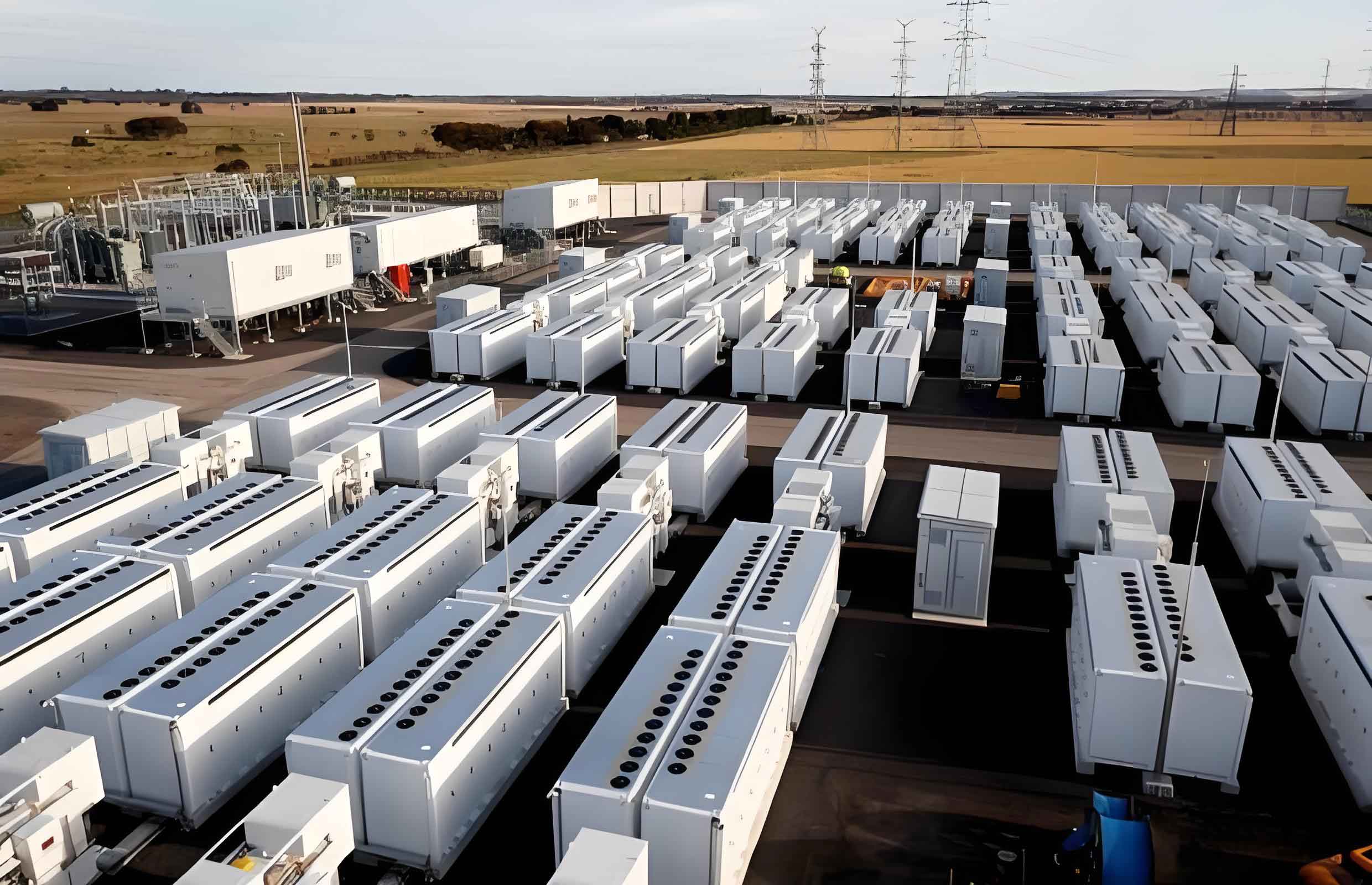
The traditional approach to **energy storage battery** placement often relies on sensitivity analyses related to specific objectives like loss minimization. While useful, these methods may overlook the fact that a power grid is an interconnected system where the failure of a single critical component can trigger cascading failures leading to widespread blackouts. Our methodology is grounded in vulnerability theory for complex networks, applied specifically to power systems. We recognize that vulnerabilities are not always at the most connected nodes but often at those whose failure causes significant operational and socio-economic disruption. Therefore, our siting strategy for the **energy storage battery** shifts from a single-objective optimization to a vulnerability-based identification process. The goal is to preemptively strengthen the grid at its weakest points by deploying **energy storage battery** resources that can provide rapid power support when those points are stressed or fail, thereby mitigating the impact of disturbances and reducing the need for drastic corrective actions like load shedding.
To systematically identify these critical nodes, we develop a composite vulnerability index. The first component considers the immediate operational impact of a node’s failure. When a bus (node) experiences a fault and is disconnected, the resulting loss of load can destabilize the system. We define the Load Loss Ratio, \(\rho_i^{\text{lost}}\), for node \(i\) as:
$$\rho_i^{\text{lost}} = \frac{\sum_{m} L_i}{L_{\text{total}}}$$
where \(L_i\) is the load at node \(i\), \(m\) is the set of loads lost due to the disconnection of node \(i\), and \(L_{\text{total}}\) is the total system load. This ratio reflects the fraction of system load affected by the node’s outage.
The second component accounts for the increased likelihood of failure due to equipment aging. Components degrade over time, and this aging process typically follows a Weibull distribution. The failure probability \(\rho_i(t)\) for equipment at node \(i\) after service time \(t\) at its maximum design temperature is modeled as:
$$\rho_i(t) = \frac{\eta}{T} \left( \frac{t}{T} \right)^{\eta-1}$$
where \(\eta\) is the shape parameter and \(T\) is the characteristic life at the maximum operating temperature. Integrating aging provides a more realistic assessment of a node’s inherent fragility over time.
By combining the operational impact and the aging factor, we obtain a preliminary vulnerability metric \(C_i\) for node \(i\):
$$C_i = \rho_i^{\text{lost}} \cdot \rho_i(t)$$
This metric reflects the expected severity and probability of disruption caused by node \(i\).
The third and crucial component incorporates socio-economic consequences. Not all load losses are equal. The disconnection of a critical hospital or data center carries far greater social and economic weight than disconnecting a residential area. Therefore, we classify loads into three priority levels and assign corresponding economic impact factors (\(\alpha\)). The socio-economic impact \(J_i\) of losing node \(i\) is:
$$J_i = \alpha_1 \cdot P_{\text{lost}_1} + \alpha_2 \cdot P_{\text{lost}_2} + \alpha_3 \cdot P_{\text{lost}_3}$$
where \(P_{\text{lost}_1}\), \(P_{\text{lost}_2}\), and \(P_{\text{lost}_3}\) are the amounts of Priority 1, 2, and 3 load lost, respectively, and \(\alpha_1 > \alpha_2 > \alpha_3\). This step ensures our **energy storage battery** placement considers not just technical stability but also the broader societal cost of outages.
Finally, the comprehensive vulnerability index \(M_i\) for node \(i\) is the product of its technical vulnerability and its socio-economic impact:
$$M_i = C_i \cdot J_i$$
Nodes are then ranked based on their \(M_i\) value. The highest-ranked nodes are deemed the most vulnerable and are selected as candidate locations for the **energy storage battery**. The logic is straightforward: by placing the **energy storage battery** at these locations, we can most effectively counteract the severe consequences of their potential failure. The ESB’s fast response can provide immediate active power support, compensate for lost generation or load, and help maintain synchronism and voltage levels during a transient event, thereby enhancing overall system resilience.
To validate our proposed vulnerability-based siting method for the **energy storage battery**, we conduct simulations on the IEEE 39-bus system. The system is modified to assign load priorities: Buses 20, 23, 25, and 39 are designated as Priority 1 loads (critical), while the remaining loads are split evenly between Priority 2 and 3. Reflecting their higher consequence, we assign economic impact factors as \(\alpha_1=3.0\), \(\alpha_2=0.8\), and \(\alpha_3=0.3\). We simulate a severe three-phase-to-ground fault on each bus at t=0.2s, cleared at t=0.3s, and record the resulting load loss and system response. We also vary equipment aging rates for different nodes to reflect realistic conditions.
The following table presents a subset of the calculated comprehensive vulnerability index \(M_i\) for the system, considering both load priority and a uniform, low baseline aging rate for simplicity.
| Node | \(\rho_i(t)\) (x10⁻⁴) | \(\rho_i^{\text{lost}}\) | \(C_i\) (x10⁻⁵) | \(J_i\) (MW-Impact) | \(M_i\) (x10⁻⁵) |
|---|---|---|---|---|---|
| 4 | 1.0 | 0.719 | 7.19 | 50.07 | 359.93 |
| 9 | 4.0 | 0.352 | 14.08 | 26.79 | 377.16 |
| 15 | 1.0 | 0.701 | 7.01 | 48.65 | 341.12 |
| 16 | 1.0 | 0.722 | 7.22 | 42.45 | 306.47 |
| 17 | 1.0 | 0.742 | 7.42 | 52.21 | 387.43 |
| 25 | 1.0 | 0.621 | 6.21 | 48.12 | 298.96 |
Analysis of the full results leads to the identification of key vulnerable nodes under different considerations, as summarized below:
| Consideration | Top Vulnerable Nodes (in order) |
|---|---|
| Load Loss Only (\(\rho_i^{\text{lost}}\)) | 17, 16, 15, 4, 14, 3 |
| Aging Considered (\(C_i\)) | 9, 28, 17, 16, 4, 15 |
| Socio-Economic Impact (\(J_i\)) | 17, 4, 15, 25, 23, 3 |
| Comprehensive Index (\(M_i\)) | 17, 9, 4, 15, 16, 25 |
The results are insightful. When considering only topological load loss (first row), nodes with high electrical centrality (like 17, 16, 15) are highlighted. Introducing aging (second row) significantly elevates nodes like 9 and 28, demonstrating that equipment condition can drastically change vulnerability assessment. Considering socio-economic impact (third row) brings critical load nodes like 25 and 23 into prominence, even if their pure load loss is not the highest. Our final comprehensive index \(M_i\) (fourth row) synthesizes all these aspects. It confirms the importance of central nodes (17, 4, 15, 16) while also elevating node 9 due to its assumed higher aging rate and node 25 due to its critical load. This list represents the optimal candidate locations for the **energy storage battery** according to our method.
We proceed to test the efficacy of placing an **energy storage battery** at one of these identified vulnerable nodes. We simulate a fault on Bus 17 (a high \(M_i\) node) under two scenarios: without ESB and with an ESB installed at Bus 17. The ESB is configured to provide fast active power support upon detecting the voltage dip associated with the fault. The comparative results for generator rotor angles and bus voltages are decisive.
Without the **energy storage battery**, the fault on Bus 17 causes severe rotor angle separation among generators, indicating loss of synchronism. The system stability can only be recovered by tripping several generators and shedding a significant amount of load. Bus voltages, particularly in the affected area, experience a deep and prolonged depression. The simulation trajectory is clearly unstable. In contrast, with the **energy storage battery** installed at Bus 17, the response is markedly improved. Upon fault clearance, the **energy storage battery** immediately injects active power into the grid. This injection provides crucial deceleration power to the accelerating generators, damping the rotor angle swings. The plot shows that the generator angles quickly settle into a stable, coherent swing pattern after the disturbance. Concurrently, the voltage profile is also stabilized more rapidly and recovers to an acceptable level without the need for extensive load shedding. The **energy storage battery** effectively acts as a fast-responding shock absorber for the transient disturbance at its location.
A similar positive effect is observed when a fault occurs on Bus 25, a critical load node identified by our index. Without support, stabilizing the system would require shedding this high-priority load, incurring the very socio-economic cost our method seeks to avoid. With an **energy storage battery** placed at or near Bus 25, the active power support helps maintain local voltage and reduces the strain on the grid, often eliminating the need to shed the critical load entirely. This validates that our vulnerability-based siting method for the **energy storage battery** successfully targets locations where its fast power support delivers maximum benefit for both transient angle stability and voltage stability, while also minimizing costly and disruptive load curtailment.
In conclusion, this paper has presented and validated a novel methodology for siting **energy storage battery** systems based on power grid node vulnerability identification under transient conditions. Moving beyond single-dimension metrics, we constructed a comprehensive vulnerability index that synthesizes the operational impact of load loss, the probabilistic risk from equipment aging, and the socio-economic consequence of different load types. This holistic approach ensures that the selected locations for the **energy storage battery** are truly the points where failure would be most damaging to the grid’s integrity and societal function. Time-domain simulation on the IEEE 39-bus system confirmed that placing an **energy storage battery** at nodes identified by this method, such as Buses 17 and 25, provides exceptional transient stability support. The ESB’s rapid power injection effectively dampens rotor angle oscillations, accelerates voltage recovery, and reduces or eliminates the need for load shedding during large disturbances. Therefore, this vulnerability-based siting framework offers a robust and effective strategy for deploying **energy storage battery** resources to enhance power system resilience and reliability in the era of high-penetration renewables.