
In this review, I examine the application of sulfide electrolytes in the solid state battery field. I have organized my discussion around materials, interfaces, composite electrodes, cell-level design, manufacturing, and application progress. Throughout the article, I use tables and equations to summarize key relationships and performance metrics. The central motivation is straightforward: the solid state battery is widely regarded as the next-generation power source for electric vehicles because it can combine high energy density with improved safety. Among the available solid electrolyte families, sulfide electrolytes are especially attractive because they offer the highest room-temperature ionic conductivity and excellent mechanical deformability. However, practical deployment still faces major challenges, including air instability, interfacial reactions, mechanical degradation, and scalable production. I summarize these challenges and the strategies that researchers are exploring to overcome them.
1. Why Sulfide Electrolytes Matter for the Solid State Battery
The conventional lithium-ion battery relies on a liquid electrolyte that contains flammable organic solvents. Although liquid electrolytes provide excellent wetting and high ionic conductivity, they also introduce safety risks and limit the attainable energy density. A solid state battery replaces the liquid electrolyte and separator with a solid electrolyte, which can potentially enable the use of lithium metal anodes and high-voltage cathodes. The solid electrolyte must simultaneously satisfy several requirements: high ionic conductivity, negligible electronic conductivity, a wide electrochemical stability window, good chemical stability, mechanical robustness, and compatibility with both electrodes. Sulfide electrolytes are among the few materials that can approach liquid-like ionic conductivity at room temperature. Some sulfide compositions reach values as high as 25 mS/cm, which is comparable to or even higher than conventional liquid electrolytes. This property makes the sulfide solid state battery one of the most promising candidates for fast charging and high-power applications.
I summarize the principal advantages of sulfide electrolytes in Table 1. These advantages are not independent; they interact in complex ways. For example, high ionic conductivity enables fast charging, but fast charging can accelerate interfacial reactions and mechanical degradation. Therefore, a holistic view is necessary.
| Property | Liquid electrolyte | Sulfide solid electrolyte | Implication for solid state battery |
|---|---|---|---|
| Flammability | High, organic solvents | Nonflammable, inorganic | Improved safety |
| Ionic conductivity at 25 °C | 10–15 mS/cm | 0.1–25 mS/cm | Fast charging possible |
| Mechanical modulus | Liquid, no shear resistance | 10–30 GPa | Can suppress dendrites to some extent |
| Electrochemical window | ~4.5 V vs Li/Li+ | 1.7–2.3 V vs Li/Li+ (intrinsic) | Requires interface engineering for high voltage |
| Air stability | Stable in sealed cell | Poor, reacts with moisture | Requires inert atmosphere |
| Processability | Easy wet processing | Cold pressing, sintering, solution processing | Scalable but sensitive |
| Interface contact | Excellent wetting | Point contact, voids form | Stack pressure often needed |
The intrinsic electrochemical window of sulfide electrolytes is often narrow, typically around 2.2 V vs Li/Li+. This means that when paired with high-voltage cathodes, the electrolyte can be oxidized. When paired with lithium metal, it can be reduced. Therefore, the practical solid state battery must use protective layers, coatings, or modified electrolyte compositions. I discuss these strategies later.
2. Representative Sulfide Electrolyte Families
Sulfide electrolytes can be broadly classified into glassy, glass-ceramic, and crystalline materials. Glassy sulfides, such as 20Li2S-80P2S5, exhibit good formability but moderate conductivity. Glass-ceramics, such as Li7P3S11, improve conductivity by precipitating conductive crystalline phases. Crystalline materials, such as Li10GeP2S12 (LGPS) and Li6PS5Cl (argyrodite), show the highest conductivities. The argyrodite family has attracted particular attention because it can be synthesized at relatively low temperatures and offers good processability. Table 2 lists representative compositions and their reported ionic conductivities.
| Family | Example composition | Ionic conductivity (mS/cm) | Key features |
|---|---|---|---|
| Glass | 20Li2S-80P2S5 | 0.1–0.3 | Good formability, low conductivity |
| Glass-ceramic | Li7P3S11 | 1–3 | Precipitated conductive phase |
| Thio-LISICON | Li3.25Ge0.25P0.75S4 | 2–5 | High conductivity, contains Ge |
| LGPS-type | Li10GeP2S12 | 10–12 | Very high conductivity, expensive Ge |
| Argyrodite | Li6PS5Cl | 1–10 | Solution processable, air sensitivity |
| Argyrodite | Li6PS5Br | 1–7 | Wider window than Cl analog |
| Argyrodite | Li5.5PS4.5Cl1.5 | 8–12 | Optimized Cl content |
| Doped argyrodite | Li6.25PS4.75N0.25Cl | 5–10 | Improved lithium stability |
| Sn-based | Li3.875Sn0.875As0.125S4 | 1–4 | Better air stability |
The development trend has moved from simple glasses to complex crystalline compounds. The goal is to maximize ionic conductivity while improving stability and reducing cost. Germanium-containing compounds such as LGPS are highly conductive but expensive. Therefore, researchers are exploring Sn, Si, and Sb substitutions. For example, Li10MP2S12 (M = Sn, Si) has been studied as a lower-cost alternative. The ionic conductivity can be tuned by changing the M element and the degree of disorder. I summarize the general formula for many sulfide electrolytes as:
$$ \text{Li}_x \text{M}_y \text{P}_z \text{S}_w \text{X}_v $$
where M is a metalloid or metal cation, and X is a halogen. The ionic conductivity depends on the lithium concentration, the framework structure, and the degree of anion disorder. In argyrodites, the anion sublattice can be occupied by S2− and X− in different arrangements, creating pathways for lithium hopping.
3. Ionic Transport Mechanisms and Equations
Ionic transport in sulfide electrolytes is usually described by the Arrhenius equation:
$$ \sigma(T) = \frac{A}{T} \exp\left(-\frac{E_a}{k_B T}\right) $$
where σ is the ionic conductivity, T is the absolute temperature, A is a pre-exponential factor, Ea is the activation energy, and kB is the Boltzmann constant. For glassy materials, the Vogel-Tammann-Fulcher (VTF) equation often provides a better fit:
$$ \sigma(T) = \sigma_0 \exp\left(-\frac{B}{T – T_0}\right) $$
where σ0 is a prefactor, B is a pseudo-activation energy, and T0 is the Vogel temperature. The VTF behavior indicates that ion transport is coupled to the segmental motion of the glassy network. In crystalline sulfides, the Arrhenius equation is usually more appropriate because the lattice provides well-defined hopping sites.
The Nernst-Einstein relation connects ionic conductivity to the diffusion coefficient:
$$ D = \frac{k_B T \sigma}{n q^2} $$
where D is the diffusion coefficient, n is the charge carrier concentration, and q is the elementary charge. This relation is useful for comparing conductivity data with diffusion measurements. The activation energy Ea is typically in the range 0.2–0.4 eV for high-performance sulfide electrolytes. Lower activation energies enable better low-temperature performance, which is critical for the solid state battery in electric vehicles.
I have compiled typical activation energies and conductivities in Table 3. The data show that the best sulfide electrolytes can achieve conductivities above 10 mS/cm with activation energies below 0.25 eV.
| Material | σ at 25 °C (mS/cm) | Ea (eV) | Structure type |
|---|---|---|---|
| Li7P3S11 | 1.5–3.0 | 0.30–0.35 | Glass-ceramic |
| Li10GeP2S12 | 10–12 | 0.22–0.25 | LGPS |
| Li6PS5Cl | 1–4 | 0.30–0.35 | Argyrodite |
| Li5.5PS4.5Cl1.5 | 8–12 | 0.24–0.28 | Argyrodite |
| Li3.875Sn0.875As0.125S4 | 1–4 | 0.30–0.38 | Thio-LISICON |
| Li6.25PS4.75N0.25Cl | 5–10 | 0.25–0.30 | Argyrodite |
4. Air Stability and Hydrolysis
The most notorious problem of sulfide electrolytes is their sensitivity to moisture. When exposed to humid air, they undergo hydrolysis reactions that release hydrogen sulfide (H2S), which is toxic, flammable, and foul-smelling. The reaction also destroys the crystal structure and reduces ionic conductivity. A general hydrolysis reaction can be written as:
$$ \text{Li}_6\text{PS}_5\text{Cl} + \text{H}_2\text{O} \rightarrow \text{Li}_2\text{S} + \text{H}_2\text{S} + \text{LiCl} + \text{phosphates} $$
The exact products depend on the composition and the amount of water. The hydrolysis process is often initiated at the surface and then propagates inward. The generation of H2S is a major safety concern and a barrier to manufacturing. Therefore, sulfide electrolytes must be handled in dry rooms or inert atmospheres, which increases cost.
To improve air stability, researchers have proposed several strategies. One approach is to substitute sulfur with oxygen or iodine. Another approach is to replace P5+ with softer acids such as Sn4+, Sb3+, or In3+. The hard-soft acid-base (HSAB) principle provides a useful guideline. Soft acids prefer soft bases such as S2−, while hard acids prefer hard bases such as O2−. By introducing softer cations, the material becomes less reactive toward moisture. Surface coatings can also protect sulfide particles. For example, a fluorinated polysiloxane coating or a Li1.4Al0.4Ti1.6(PO4)3 nanoparticle layer can act as a barrier against oxygen, water, and organic solvents. Table 4 summarizes common strategies and their effects.
| Strategy | Example | Effect on air stability | Effect on conductivity |
|---|---|---|---|
| O substitution | Li6PS4.75ClO0.25 | Reduced H2S generation | Slight decrease |
| I substitution | Li5.6PS4.6I1.4 | Improved moisture resistance | Moderate conductivity retained |
| Soft acid substitution | Li3.875Sn0.875As0.125S4 | Better air stability | Moderate |
| Surface coating | Fluorinated polysiloxane | Barrier against moisture | Small interfacial resistance increase |
| Surface coating | Li1.4Al0.4Ti1.6(PO4)3 | Protective layer | Needs optimization |
| Bulk doping | Li6.25PS4.75N0.25Cl | Improved chemical stability | Conductivity maintained |
Despite these advances, no sulfide electrolyte is completely stable in ambient air. Therefore, the solid state battery manufacturing process must still use controlled environments. I believe that a combination of bulk doping and surface protection will be necessary for practical deployment.
5. Cathode Interface and Space Charge Layer
The cathode/sulfide electrolyte interface is a critical bottleneck. Three main problems arise: (1) electrochemical side reactions, (2) mechanical contact loss due to volume changes, and (3) space charge layer formation. The space charge layer occurs because lithium ions have different chemical potentials in the cathode and the electrolyte. Lithium ions migrate from the sulfide electrolyte to the oxide cathode, creating a lithium-depleted region in the electrolyte near the interface. This depletion layer increases interfacial resistance. The potential distribution in the space charge layer can be described by the Poisson equation:
$$ \frac{d^2 \phi}{dx^2} = -\frac{\rho(x)}{\varepsilon_r \varepsilon_0} $$
where φ is the electrostatic potential, ρ is the charge density, εr is the relative permittivity, and ε0 is the vacuum permittivity. The characteristic thickness of the space charge layer is the Debye length:
$$ L_D = \sqrt{\frac{\varepsilon_r \varepsilon_0 k_B T}{2 e^2 c_0}} $$
where c0 is the bulk lithium concentration. For typical sulfide electrolytes, LD is on the order of a few nanometers. Although this layer is thin, it can significantly increase interfacial resistance. To mitigate the space charge layer, a buffer layer with intermediate chemical potential can be inserted between the cathode and the electrolyte. The buffer layer should be ionically conductive and electronically insulating. Table 5 lists common buffer materials and their functions.
| Buffer material | Function | Conductivity | Stability |
|---|---|---|---|
| LiNbO3 | Suppresses space charge and side reactions | Moderate | Good with NCM |
| Li2CoTi3O8 | Ionic bridge | Moderate | Good |
| LiZr2(PO4)3 | Stable interface | Low–moderate | Good |
| Li3BO3 | Flux and protective layer | Low | Good |
| Li0.35La0.55TiO3 | Ionic conduction | Moderate | Needs optimization |
In addition to buffer layers, cathode active material modification is important. For high-nickel layered oxides such as LiNi0.8Mn0.1Co0.1O2 (NCM811), the surface can be coated with a thin oxide or fluoride layer. Single-crystal cathodes are also beneficial because they reduce particle cracking and void formation. The combination of single-crystal NCM and a LiNbO3-Li3BO3 coating has been shown to improve cycling stability in sulfide solid state battery cells.
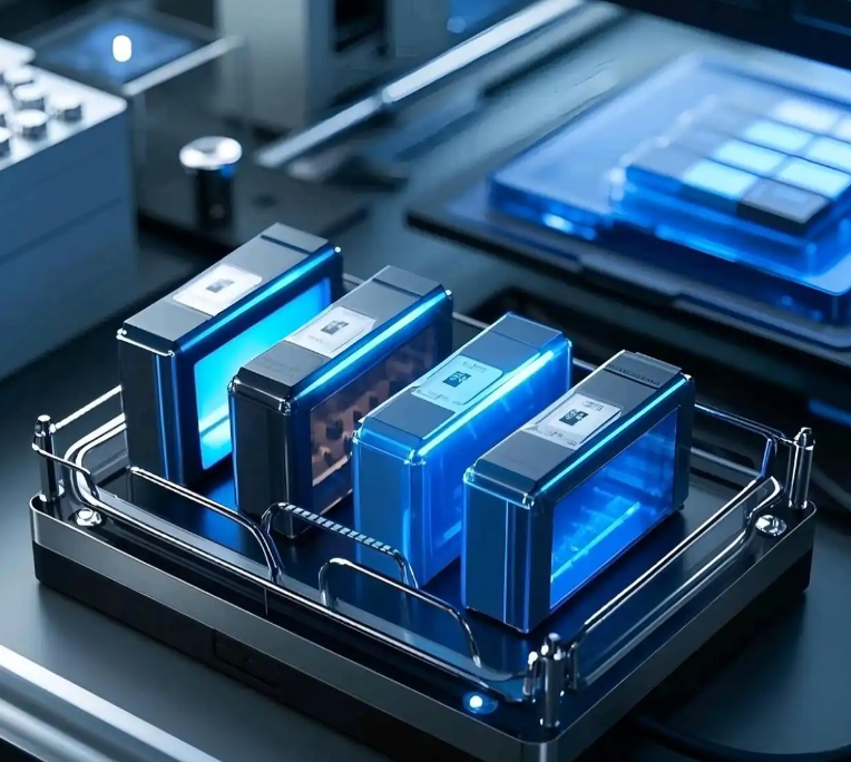
The schematic of a sulfide solid state battery is shown below. It illustrates the layered structure of the composite cathode, the sulfide electrolyte separator, and the anode.
The interfacial resistance can be modeled as a series combination of bulk and interfacial contributions:
$$ R_{total} = R_{bulk} + R_{int} + R_{cathode} + R_{anode} $$
where Rint is the interfacial resistance. Reducing Rint is essential for high-power operation. The Butler-Volmer equation describes the kinetics of lithium transfer across the interface:
$$ i = i_0 \left[ \exp\left(\frac{\alpha_a F \eta}{RT}\right) – \exp\left(-\frac{\alpha_c F \eta}{RT}\right) \right] $$
where i is the current density, i0 is the exchange current density, αa and αc are transfer coefficients, F is the Faraday constant, η is the overpotential, R is the gas constant, and T is the temperature. A high i0 indicates facile interfacial kinetics. Interface engineering aims to increase i0 and reduce η.
6. Anode Interface and Lithium Dendrites
The anode/sulfide electrolyte interface is equally challenging. When lithium metal is used, several problems occur: (1) interfacial side reactions that form high-resistance products such as Li2S, (2) large volume changes during plating and stripping, and (3) lithium dendrite growth that can penetrate the electrolyte and cause short circuits. The reaction between lithium and sulfide electrolyte can be written as:
$$ \text{Li} + \text{Li}_6\text{PS}_5\text{Cl} \rightarrow \text{Li}_2\text{S} + \text{Li}_3\text{P} + \text{LiCl} $$
These products are mixed ionic-electronic conductors, which can continuously consume the electrolyte. To stabilize the interface, artificial interlayers are often introduced. Common interlayer materials include Al2O3, BiBr3, polypropylene carbonate (PPC), and LixSiOy. These layers should be chemically stable against lithium, ionically conductive, and mechanically robust. Table 6 summarizes anode interface strategies.
| Strategy | Example material | Function | Challenges |
|---|---|---|---|
| Artificial interlayer | Al2O3 | Blocks side reactions | May increase resistance |
| Artificial interlayer | BiBr3 | Forms stable Li-Bi alloy | Processing complexity |
| Polymer interlayer | PPC | Buffers volume change | Limited thermal stability |
| Inorganic interlayer | LixSiOy | Ionic conduction | Thickness control |
| Bulk doping | Li5.6PS4.6I1.4 | Improves lithium stability | Conductivity trade-off |
| Alloy anode | Li-In alloy | Reduces dendrite growth | Dendrites still possible at high current |
| Liquid anode | Li-Bp-DME | Conformal contact | Complex cell design |
Dendrite growth is governed by the critical current density (CCD). A simplified expression for CCD is:
$$ J_{crit} = \frac{2 \pi \gamma}{a \Omega} \left( \frac{1}{E_{Li}} + \frac{1}{E_{SE}} \right)^{-1} $$
where γ is the surface energy, a is the initial defect size, Ω is the molar volume, and E is the elastic modulus. The equation shows that increasing the modulus of the solid electrolyte increases the critical current density. However, sulfide electrolytes are relatively soft compared to oxides, so dendrites can still grow under high current. Stack pressure also plays a role. Higher stack pressure can improve contact but may also induce creep and mechanical degradation. Therefore, optimizing pressure is essential.
7. Composite Electrodes and Charge Transport
The composite electrode is a porous mixture of active material, solid electrolyte, conductive carbon, and binder. Charge transport in this structure is complex. The effective ionic conductivity of the composite can be described by percolation theory:
$$ \sigma_{eff} = \sigma_0 (\phi – \phi_c)^t $$
where φ is the volume fraction of the solid electrolyte, φc is the percolation threshold, and t is a critical exponent. Typically, φc is around 0.15–0.25, and t is between 1.5 and 2.0. The electronic conductivity follows a similar percolation law for the carbon additive. The tortuosity of the transport pathways also affects performance:
$$ \tau = \frac{L_{eff}}{L} $$
where Leff is the actual path length and L is the straight-line distance. Higher tortuosity reduces effective conductivity. The effective conductivity can be written as:
$$ \sigma_{eff} = \frac{\sigma_0 \varepsilon}{\tau} $$
where ε is the porosity. Table 7 summarizes key composite electrode parameters and their impact.
| Parameter | Symbol | Typical range | Impact on solid state battery |
|---|---|---|---|
| Electrolyte volume fraction | φ | 0.20–0.40 | Higher φ improves ionic percolation |
| Carbon content | wC | 1–5 wt% | Too much carbon accelerates electrolyte decomposition |
| Porosity | ε | 5–20% | High porosity lowers effective conductivity |
| Tortuosity | τ | 2–10 | Lower τ improves rate capability |
| Particle size of active material | dAM | 1–10 µm | Smaller particles shorten diffusion length |
| Particle size of electrolyte | dSE | 0.5–5 µm | Smaller particles improve contact |
| Binder content | wb | 1–5 wt% | Binder can block ionic pathways |
To maximize performance, the composite electrode should have a high electrolyte content, low tortuosity, and a well-connected electronic network. However, increasing electrolyte content reduces the overall energy density because the electrolyte is not electrochemically active. Therefore, a balance must be found. Mathematical modeling is increasingly used to optimize electrode composition and microstructure. The electrochemical reaction rate is often modeled by the Butler-Volmer equation coupled with diffusion equations:
$$ \frac{\partial c}{\partial t} = D \nabla^2 c + \frac{s}{nF} \nabla \cdot \mathbf{i} $$
where c is the lithium concentration, D is the diffusion coefficient, s is the stoichiometric coefficient, n is the number of electrons, F is Faraday’s constant, and i is the current density. These models help identify limiting factors such as slow diffusion in the active material or poor ionic percolation in the electrolyte phase.
8. Mechanical Failure and Thermal Management
Mechanical degradation is a major cause of capacity fade in sulfide solid state battery cells. During cycling, the active material particles expand and contract. For example, silicon anodes can experience volume changes of 300% or more. Even layered oxide cathodes show 2–5% volume changes. These changes create stress at the interfaces and within the composite electrode. The stress can be estimated using Hooke’s law:
$$ \sigma = E \epsilon $$
where σ is stress, E is Young’s modulus, and ε is strain. If the stress exceeds the fracture strength, cracks form. The fracture criterion for a pre-existing crack is given by the stress intensity factor:
$$ K_I = Y \sigma \sqrt{\pi a} $$
where KI is the mode I stress intensity factor, Y is a geometry factor, and a is the crack length. If KI exceeds the fracture toughness KIC, the crack propagates. In sulfide electrolytes, crack propagation can lead to electrolyte fracture and short circuits. In composite electrodes, void formation at the cathode/electrolyte interface is common. These voids increase impedance and reduce active contact area.
Thermal management is another critical issue. Sulfide electrolytes have low thermal conductivity, typically around 0.5–1.5 W/(m·K). Heat generated during cycling cannot be easily removed, leading to local hotspots. The temperature rise can accelerate side reactions and degrade performance. The heat generation rate can be modeled as:
$$ \dot{Q} = I^2 R_{total} + I T \frac{\partial U}{\partial T} $$
where Qdot is the heat generation rate, I is current, Rtotal is total resistance, and ∂U/∂T is the entropic coefficient. Advanced cooling designs, such as integrated microchannels or thermally conductive fillers, are needed. Table 8 summarizes mechanical and thermal challenges.
| Challenge | Cause | Effect | Mitigation |
|---|---|---|---|
| Interface contact loss | Volume changes | High impedance | Stack pressure, compliant interlayers |
| Particle cracking | Cyclic stress | Loss of active material | Single-crystal particles |
| Void formation | Lithium removal | Current constriction | Optimized cathode composition |
| Dendrite growth | Nonuniform plating | Short circuit | Interlayers, high modulus electrolyte |
| Low thermal conductivity | Inherent material property | Hotspots, thermal runaway | Thermal fillers, cooling plates |
| Creep | Stack pressure | Electrolyte deformation | Optimized pressure, temperature control |
9. Cell Design and Manufacturing
The design of a practical solid state battery cell must integrate electrodes, electrolyte, current collectors, and packaging. The cell architecture can be planar, bulk, or bipolar. Planar cells are easy to fabricate but have low energy density. Bulk cells stack multiple layers to increase capacity. Bipolar cells connect cells in series within a single package, which reduces inactive components. However, bipolar design requires stable interfaces and effective sealing.
Manufacturing sulfide solid state battery cells involves several steps: electrolyte synthesis, electrode slurry preparation, casting or pressing, stacking, and packaging. Because sulfide electrolytes are moisture-sensitive, all steps must be performed in a dry room with a dew point below −40 °C. The stack pressure during operation is critical. Typically, pressures of 1–10 MPa are applied to maintain contact. However, high pressure can cause creep and mechanical failure. The optimal pressure depends on the materials and the cell design. Table 9 compares different manufacturing methods.
| Method | Description | Advantages | Disadvantages |
|---|---|---|---|
| High-temperature solid-state reaction | Mixing and sintering at 500–1000 °C | High crystallinity | High energy cost, inhomogeneity |
| Mechanical ball milling | High-energy milling in inert atmosphere | Small particle size | Contamination, long time |
| Solution processing | Dissolution in organic solvent, precipitation | Scalable, uniform mixing | Solvent sensitivity, cost |
| Sol-gel | Controlled hydrolysis and condensation | Molecular-level mixing | Complex, cracking |
| Microwave-assisted synthesis | Rapid heating | Short time, uniform | Scale-up challenges |
| Continuous production | Roll-to-roll or extrusion | High throughput | Equipment development needed |
Cost is a major barrier. Lithium sulfide (Li2S) is one of the most expensive precursors, accounting for nearly 80% of the raw material cost. Reducing Li2S cost is essential. Researchers are exploring alternative lithium sources, recycling of spent batteries, and new synthesis routes. The production environment also adds cost because of the need for inert gas systems and dry rooms. Standardizing the manufacturing process and developing low-cost equipment will be necessary for mass production.
10. Application Progress and Industrial Landscape
Several regions and companies are actively developing sulfide solid state battery technology. I summarize the general progress without referring to specific individuals or addresses. In Asia, automotive and battery manufacturers have invested heavily in sulfide-based solid state battery research. Some companies have demonstrated prototype cells with energy densities of 300–400 Wh/kg. Others have reported cycling stability over 1000 cycles. In Europe and North America, research consortia and startups are focusing on materials, interfaces, and manufacturing. Table 10 provides a qualitative overview of application progress.
| Region/Entity type | Focus | Demonstrated performance | Challenges |
|---|---|---|---|
| Asian automotive manufacturers | Sulfide solid state battery for EVs | 300–400 Wh/kg prototype cells | Cost, scalability |
| Asian battery manufacturers | Argyrodite and LGPS electrolytes | 10 Ah-class cells | Interface stability |
| European research institutes | Interface engineering | Improved cycle life | Pilot-scale production |
| North American startups | Lithium metal anodes | High energy density | Dendrite suppression |
| Global equipment suppliers | Dry room and stacking equipment | Scalable processes | High capital cost |
Despite the progress, no company has achieved true mass production of sulfide solid state battery cells. The main obstacles are material instability, interface failure, electrode design, and manufacturing yield. However, the pace of research and development is accelerating. Patent activity has grown rapidly, indicating strong commercial interest. I expect that the first commercial applications will be in premium electric vehicles, followed by broader adoption as costs decline.
11. Future Directions
To realize practical sulfide solid state battery technology, several research directions should be prioritized. First, cost reduction is essential. New synthesis methods such as microwave-assisted synthesis and continuous flow production can reduce energy consumption and improve uniformity. Recycling of lithium and sulfur from spent batteries can also lower raw material costs. Second, interface engineering must be advanced. Stable buffer layers for both cathode and anode are needed. Atomic layer deposition and molecular layer deposition can create ultrathin, conformal coatings. Third, integrated cell design should be adopted. Instead of treating electrodes, electrolyte, and thermal management as separate modules, they should be co-designed. For example, the electrode porosity and particle size should be optimized for electrolyte infiltration, and the thermal management system should account for the temperature dependence of ionic conductivity. Fourth, advanced characterization and modeling are needed. In situ microscopy, spectroscopy, and electrochemical impedance spectroscopy can reveal degradation mechanisms. Multiscale models can predict performance and guide materials discovery.
I also emphasize the importance of collaboration. The solid state battery field is highly interdisciplinary. Universities, research institutes, battery manufacturers, material suppliers, and automotive companies must work together. Pre-competitive research consortia can share fundamental knowledge while individual companies focus on proprietary manufacturing. Standardization of testing protocols is also needed to compare performance fairly. Table 11 summarizes future research priorities.
| Priority | Action | Expected outcome |
|---|---|---|
| Cost reduction | Microwave synthesis, continuous production, recycling | Lower $/kWh |
| Interface engineering | ALD coatings, buffer layers, doped electrolytes | Stable interfaces, long cycle life |
| Integrated design | Co-design of electrode, electrolyte, thermal management | Higher energy density, better safety |
| Advanced characterization | In situ techniques, multiscale modeling | Deeper understanding of degradation |
| Collaboration | Industry-academia partnerships, standard protocols | Faster commercialization |
12. Conclusion
In this review, I have discussed the application of sulfide electrolytes in the solid state battery. Sulfide electrolytes offer the highest ionic conductivity among solid electrolytes, making them the most promising candidate for high-energy-density and fast-charging solid state battery cells. However, they suffer from air instability, narrow electrochemical windows, interfacial reactions, and mechanical degradation. I have summarized the key equations and tables that describe ionic transport, interfacial resistance, composite electrode behavior, and mechanical failure. I have also outlined the current application landscape and future research directions. The path to commercialization requires advances in materials, interfaces, cell design, and manufacturing. With sustained collaboration and innovation, the sulfide solid state battery can become a viable technology for next-generation electric vehicles and energy storage systems.
In my view, the most critical near-term milestone is the demonstration of a sulfide solid state battery cell that can cycle for more than 1000 cycles with less than 20% capacity fade while maintaining a stack pressure below 5 MPa. This would represent a major step toward practical deployment. Beyond that, cost reduction to below $100/kWh will be necessary for mass adoption. I am optimistic that these goals can be achieved through the combined efforts of the global research and industrial community.