
The increasing penetration of distributed generation systems has brought the control of power electronic interfaces, particularly utility interactive inverters, to the forefront of grid stability research. As the critical link between distributed DC sources and the AC utility grid, the performance demands on these voltage-source inverters are stringent. Their switching operation inherently introduces high-frequency harmonics, posing a challenge to power quality and system stability. To mitigate this, LCL filters are widely adopted at the output of utility interactive inverters due to their superior harmonic attenuation capability compared to simple L-type filters, allowing for reduced inductor size and weight. However, the LCL filter introduces a third-order resonant peak, which can destabilize the system if not properly damped.
Conventional linear control strategies for LCL-type utility interactive inverters often combine a Proportional-Resonant (PR) controller for grid current regulation with an active damping (AD) method, typically capacitor current feedback, to suppress the LCL resonance. While effective under ideal grid conditions, this PR-AD strategy suffers from inherent limitations. The digital control loop, encompassing computation and Pulse Width Modulation (PWM) delays, significantly reduces the system’s achievable bandwidth. This becomes critically problematic under weak grid conditions, characterized by a large grid impedance ($L_g$). The weak grid lowers the LCL resonance frequency ($f_{res}$), potentially pushing it into a frequency region where the phase lag from the digital delay jeopardizes stability. This bandwidth limitation fundamentally restricts the controller’s robustness to grid impedance variations.
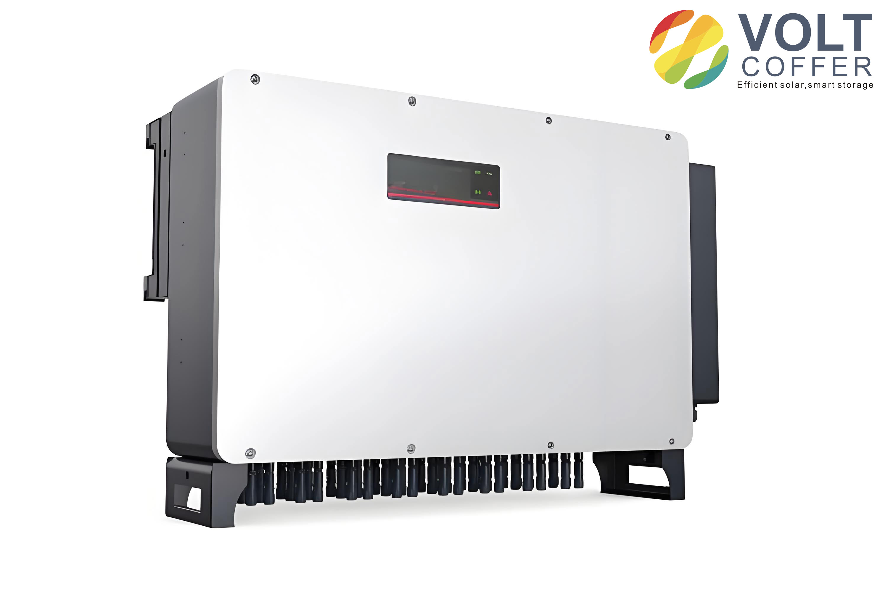
To address these challenges, this article presents a novel cascade control strategy termed PR-MPC. The outer loop retains a PR controller for precise grid current tracking. The key innovation lies in the inner loop, where a low-complexity, multi-objective Finite Control Set Model Predictive Control (FCS-MPC) replaces the conventional PWM modulator and active damping path. This approach eliminates the modulation delay, thereby extending the system bandwidth and enhancing robustness. Furthermore, the FCS-MPC is designed with a dual-objective cost function to inherently damp the LCL resonance without requiring separate damping parameter tuning.
System Modeling and Challenge Analysis
The topology of a three-phase LCL-filtered utility interactive inverter is considered. The system dynamics in the continuous-time domain can be described by the following state-space representation, where the state vector comprises the inverter-side inductor current ($i_f$), the capacitor voltage ($v_f$), and the grid current ($i_g$):
$$
\frac{d}{dt}\begin{bmatrix} i_f \\ v_f \\ i_g \end{bmatrix} = A \begin{bmatrix} i_f \\ v_f \\ i_g \end{bmatrix} + B \begin{bmatrix} v_i \\ v_g \end{bmatrix}
$$
with
$$
A = \begin{bmatrix}
0 & -\frac{1}{L_f} & 0 \\
\frac{1}{C_f} & 0 & -\frac{1}{C_f} \\
0 & \frac{1}{L_{fg}+L_g} & 0
\end{bmatrix}, \quad
B = \begin{bmatrix}
\frac{1}{L_f} & 0 \\
0 & 0 \\
0 & -\frac{1}{L_{fg}+L_g}
\end{bmatrix}
$$
The transfer function from the inverter output voltage $v_i$ to the grid current $i_g$ is a third-order system:
$$
G_{LCL}(s) = \frac{i_g(s)}{v_i(s)} = \frac{1}{s(L_f C_f (L_{fg}+L_g)s^2 + (L_f + L_{fg} + L_g))}
$$
The undamped LCL filter exhibits a resonant peak at frequency $f_{res}$:
$$
f_{res} = \frac{1}{2\pi}\sqrt{\frac{L_f + L_{fg} + L_g}{L_f C_f (L_{fg}+L_g)}}
$$
This resonance introduces a -180° phase jump and a significant gain peak in the frequency response, threatening stability. In a weak grid, $L_g$ increases, causing $f_{res}$ to decrease. Digital delay in conventional controllers adds significant phase lag at this lower frequency, making the system prone to instability, as illustrated in the comparative analysis below.
| Control Aspect | Conventional PR-AD | Proposed PR-MPC |
|---|---|---|
| Inner Loop | PWM with Capacitor-Current Feedback AD | Finite Control Set Model Predictive Control (FCS-MPC) |
| Modulation Delay | ~0.5 to 1 sampling period ($T_s$) | Eliminated (direct switching) |
| Resonance Damping | Active damping via feedback, parameter-sensitive | Inherent damping via multi-objective cost function |
| System Bandwidth | Limited by total digital delay | Higher, limited mainly by sampling frequency |
| Robustness to $L_g$ | Poor in weak grid (low $f_{res}$) | Strong, maintains stability |
The Proposed PR-MPC Control Strategy
The proposed control architecture for the utility interactive inverter is a cascade structure. The outer loop generates the capacitor voltage reference ($v_f^*$) using a standard PR controller to ensure zero steady-state error at the fundamental and selected harmonic frequencies (e.g., 5th, 7th). The core contribution is the design of the inner-loop FCS-MPC.
Dual-Objective Cost Function for Inherent Damping
Resonance in higher-order systems like the LCL filter stems from uncontrolled energy exchange among passive components. The proposed FCS-MPC addresses this by defining a dual-objective cost function $J$ that directly regulates the energy-related states: the capacitor voltage and the inverter-side inductor current. This simultaneous regulation provides intrinsic damping.
$$
J = J_1 + \lambda J_2
$$
where $J_1$ is the tracking error for the capacitor voltage and $J_2$ is the tracking error for the inverter-side current, both evaluated in the stationary ($\alpha\beta$) frame for the next sampling instant $(k+1)$:
$$
\begin{aligned}
J_1 &= \left( v_{f\alpha}^*(k+1) – v_{f\alpha}(k+1) \right)^2 + \left( v_{f\beta}^*(k+1) – v_{f\beta}(k+1) \right)^2 \\
J_2 &= \left( i_{f\alpha}^*(k+1) – i_{f\alpha}(k+1) \right)^2 + \left( i_{f\beta}^*(k+1) – i_{f\beta}(k+1) \right)^2
\end{aligned}
$$
The weighting factor $\lambda$ balances the two objectives. A per-unit-based design method is used for systematic tuning:
$$
\lambda = m \left( \frac{v_{f,N}}{i_{g,N}} \right)^2
$$
where $v_{f,N}$ and $i_{g,N}$ are the nominal capacitor voltage and grid current, and $m$ is a tuning parameter between 0 and 1.
Discrete Predictive Model
To evaluate the cost function, predictions for $v_f(k+1)$ and $i_f(k+1)$ are required. The continuous state-space model is discretized using a Zero-Order Hold (ZOH) method with a sampling period $T_s$:
$$
\begin{bmatrix} i_f(k+1) \\ v_f(k+1) \end{bmatrix} = A_d \begin{bmatrix} i_f(k) \\ v_f(k) \end{bmatrix} + B_d \begin{bmatrix} v_i(k) \\ i_g(k) \end{bmatrix}
$$
Here, $A_d = e^{A T_s}$ and $B_d = \int_{0}^{T_s} e^{A \tau} d\tau \, B$ are the discrete-time system matrices. This model allows the controller to predict the system’s behavior for each possible voltage vector $v_i$ generated by the inverter’s eight switching states.
Low-Complexity FCS-MPC via Optimal Reference Calculation
A standard FCS-MPC would evaluate the prediction model and cost function eight times per cycle, once for each switching state. To reduce computational burden, a simplified method is derived. First, the optimal inverter voltage vector $v_i^*$ that minimizes the primary dual-objective cost function $J$ is analytically derived using the minimization principle:
$$
\min_{\{v_{i\alpha}, v_{i\beta}\}} J(i_f(k), v_f(k))
$$
Setting the partial derivatives $\partial J / \partial v_{i\alpha}=0$ and $\partial J / \partial v_{i\beta}=0$ yields the optimal reference voltage in complex form:
$$
\begin{aligned}
v_i^*(k) &= \gamma_1 i_f^*(k+1) + \gamma_2 v_f^*(k+1) + \gamma_3 i_f(k) + \gamma_4 v_f(k) + \gamma_5 i_g(k)
\end{aligned}
$$
The coefficients $\gamma_1$ to $\gamma_5$ are constants derived from the matrices $A_d$ and $B_d$ and the weight $\lambda$. References $i_f^*(k+1)$ and $v_f^*(k+1)$ are obtained via extrapolation from their current and past reference values.
Second, a simplified tracking cost function $J_3$ is defined:
$$
J_3 = | v_i^* – v_i |^2
$$
The control algorithm now simply calculates $v_i^*$ once per cycle and then evaluates $J_3$ for the eight possible inverter voltage vectors ($v_i$), selecting the one that minimizes $J_3$. This replaces eight predictions with one reference calculation and eight simple distance calculations, drastically lowering complexity while preserving performance.
Delay Compensation
In practical digital implementation, computation time introduces a one-step delay. To compensate, a two-step prediction horizon is employed. The prediction model is used to first estimate the states at $k+1$ using the optimal switch applied from the previous cycle. These estimated states are then used as the initial condition for the prediction and optimization for time $k+2$. The optimal switching state resulting from this process is finally applied at the beginning of the $(k+1)$-th period, effectively compensating for the computational delay.
Experimental Validation and Performance Analysis
The proposed PR-MPC strategy was validated on a three-phase utility interactive inverter prototype and compared against the conventional PR-AD strategy. Key system parameters are summarized below.
| Parameter | Symbol | Value |
|---|---|---|
| DC-Link Voltage | $V_{dc}$ | 700 V |
| Sampling Freq. (PR-MPC) | $f_s$ | 50 kHz |
| Inverter-side Inductor | $L_f$ | 2.4 mH |
| Grid-side Inductor | $L_{fg}$ | 1.8 mH |
| Filter Capacitor | $C_f$ | 15 µF |
| Grid Inductance (Weak Grid) | $L_g$ | 7.0 mH |
Steady-State Performance under Weak Grid
Under a weak grid condition ($L_g = 7.0$ mH), the proposed PR-MPC controller for the utility interactive inverter demonstrated superior steady-state performance. The grid current Total Harmonic Distortion (THD) was significantly lower at 2.82%, compared to 5.86% for the conventional PR-AD controller. More importantly, the current ripple ($i_{g,ripp}$) and capacitor voltage ripple ($v_{f,ripp}$) were substantially reduced with PR-MPC, indicating effective resonance suppression and inherent damping. No resonant oscillations were observed with PR-MPC, confirming its robustness.
Dynamic Performance
The dynamic response was tested with a step change in the grid current reference from 0 A to 7 A. The utility interactive inverter with the PR-MPC strategy exhibited a much faster transient response, settling within approximately 5 ms, compared to over 30 ms for the PR-AD strategy. This verifies the enhanced bandwidth achieved by eliminating the modulation delay in the control loop of the utility interactive inverter.
| Performance Metric | Weak Grid (L_g=7 mH) | |
|---|---|---|
| PR-AD | PR-MPC | |
| Steady-State | ||
| Grid Current THD (%) | 5.86 | 2.82 |
| Grid Current Ripple (A) | 0.653 | 0.128 |
| Dynamic | ||
| Step Response Time (ms) | 30 | 5 |
Robustness to Grid Voltage Disturbances
The robustness of the utility interactive inverter was further tested under a 25% single-phase grid voltage dip. Both strategies maintained three-phase current symmetry. However, the PR-MPC strategy maintained a lower grid current THD (4.11% vs. 7.62%), demonstrating stronger fault ride-through capability and better rejection of grid voltage disturbances.
Conclusion
This article has presented a PR-MPC cascade control strategy to address the robustness limitations of conventional linear controllers for LCL-filtered utility interactive inverters in weak grids. The core of the strategy is a low-complexity, dual-objective FCS-MPC inner loop. By removing the PWM modulation stage, the system’s digital delay is minimized, leading to a higher control bandwidth. The multi-objective cost function provides inherent damping for the LCL resonance, eliminating the need for sensitive active damping parameter tuning. Furthermore, the derivation of an optimal inverter voltage reference significantly reduces the computational load of the predictive algorithm. Comprehensive experimental results confirm that the proposed PR-MPC strategy endows the utility interactive inverter with superior steady-state performance, faster dynamic response, and significantly enhanced robustness against weak grid impedance variations and grid voltage disturbances, compared to the traditional PR-AD approach.