
In the realm of renewable energy integration, three-phase photovoltaic on-grid inverters play a pivotal role in converting DC power from solar panels into AC power synchronized with the grid. However, these on-grid inverter systems often face challenges related to resonance, which can destabilize the grid, cause current and voltage distortions, and impair overall system reliability. Traditional resonance suppression methods, such as phase-locked control, frequently suffer from instability due to negative resistance characteristics in equivalent loops, leading to inadequate performance. In this paper, I propose a novel resonance suppression method based on virtual resistance for three-phase photovoltaic on-grid inverters. This approach aims to enhance stability by dynamically adjusting equivalent impedance, thereby mitigating resonance effectively. I will delve into the resonance characteristics, analyze frequency responses using virtual resistance, and present strategies for suppressing resonant circulating currents. Through extensive simulation and analysis, I demonstrate the efficacy of this method, highlighting its potential for real-world applications.
The integration of photovoltaic systems into three-phase grids involves complex interactions between inverter parameters, grid impedance, and load conditions. Resonance in on-grid inverters typically arises from mismatches in inductive and capacitive components, often exacerbated by variable grid impedance and multiple inverter parallel operations. Existing methods, including improved active disturbance rejection control and capacitor current feedback active damping, have limitations in handling dynamic grid conditions. For instance, they may rely on simplified models that overlook nonlinearities or require precise parameter tuning, which can be impractical in fluctuating environments. My method leverages virtual resistance—a conceptual impedance element—to adaptively control resonance without compromising system stability. By embedding virtual resistance into the control loop, I can emulate damping effects that counteract resonant peaks, ensuring smoother operation of the on-grid inverter. This approach not only addresses frequency deviations but also minimizes harmonic distortions, making it suitable for large-scale photovoltaic deployments.
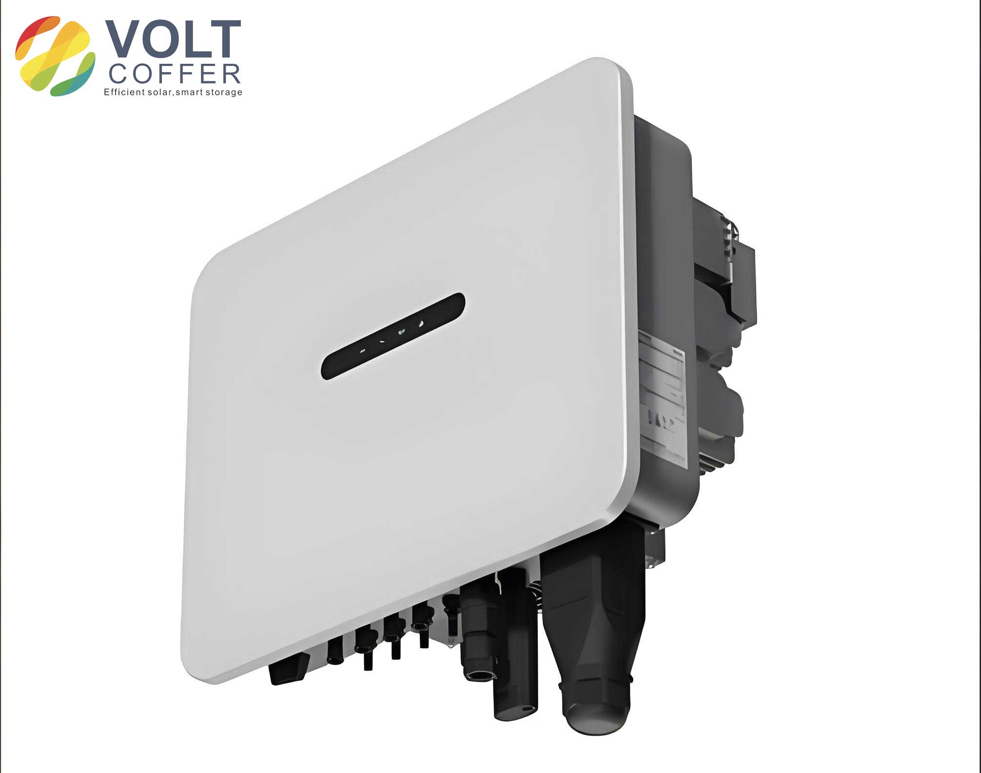
To begin, I analyze the resonance characteristics of three-phase photovoltaic on-grid inverters. When multiple inverters are connected in parallel, the grid impedance is amplified, leading to distinct resonant frequencies that can shift based on operational parameters. The resonance frequency, denoted as \(f_g\), can be derived from the equivalent circuit model of the on-grid inverter system. Consider a system with inverter-side inductance \(L_1\), grid-side inductance \(L_2\), and grid inductance \(L_g\), along with a DC-link capacitor \(C\). For \(N\) parallel inverters, the resonance frequency is given by:
$$f_g = \frac{1}{2\pi} \sqrt{\frac{L_1 + L_2 + N L_g}{L_1 (L_2 + n L_g) C}}$$
Here, \(n\) represents the resonant point influenced by impedance variations. As the number of on-grid inverters increases, resonant peaks multiply, and currents escalate, often causing instability. I observe that resonance tends to migrate to lower frequency bands, typically settling around 1.5 kHz under uniform parameters. This behavior underscores the need for adaptive suppression techniques that can handle impedance changes. Virtual resistance serves as a tool to model these variations, allowing me to decouple resonance from equivalent impedance effects. By introducing a virtual resistor \(R_v\) into the system, I can manipulate the damping characteristics without altering physical components. This is crucial for maintaining stability in photovoltaic on-grid inverter networks, where grid conditions are rarely static.
Next, I explore the resonance frequency response analysis based on virtual resistance. The concept of virtual resistance involves adding an artificial impedance term to the control algorithm of the on-grid inverter, which mimics the behavior of a physical resistor but with programmable values. This enables real-time adjustment of damping factors to suppress resonance. To understand the system dynamics, I examine the root locus of the closed-loop transfer function as virtual resistance varies. Let the virtual resistance coefficient be denoted by \(\lambda\), and the system characteristic roots be \(\lambda_1\), \(\lambda_2\), and \(\lambda_3\). As \(\lambda\) increases from 0.01 to 2, the roots move in the complex plane, affecting system stability. The root locus diagram illustrates that for moderate values of \(\lambda\), the roots remain in the left-half plane, ensuring stability. However, excessive virtual resistance can push roots toward the imaginary axis, potentially triggering instability. Therefore, I optimize \(\lambda\) to balance damping and performance. The equivalent impedance with virtual resistance is expressed as:
$$Z_{eq} = R_i + R_{vi} + j\omega L_i$$
where \(R_i\) is the inherent resistance, \(R_{vi}\) is the virtual resistance component, and \(L_i\) is the inductance. For multiple on-grid inverters, the power sharing and voltage drop relationships must be coordinated. The virtual resistance value \(R_r\) is calculated based on active power \(P\) and voltage \(U\):
$$R_r = k_{pi} \frac{P}{U} \frac{R_i + R_{vi}}{R_j + R_{vj}}$$
Here, \(k_{pi}\) is a proportional gain, and subscripts \(i\) and \(j\) refer to different inverter branches. By tuning \(k_{pi}\) and \(\lambda\), I can adjust the resonance suppression parameters to prevent frequency shifts in the photovoltaic on-grid inverter system. The frequency response at resonance \(\omega_r\) is given by:
$$\frac{C(j\omega_r)}{R_r(j\omega_r)} = \frac{R_r}{R_i + R_{vi}}{R_j + R_{vj}} \frac{G(j\omega_r)}{1 + G(j\omega_r) H(j\omega_r)}$$
In this equation, \(G(j\omega_r)\) represents the forward path gain, and \(H(j\omega_r)\) denotes the feedback gain. When \(G(j\omega_r)H(j\omega_r) > -1\), the system remains stable, and resonance is suppressed. I design \(H(j\omega_r)\) to provide negative feedback at resonant frequencies, thereby reducing peak gains. This analytical framework allows me to predict and mitigate resonance in various operating scenarios for the on-grid inverter.
To further enhance resonance suppression, I address the issue of resonant circulating currents in three-phase photovoltaic on-grid inverters. Circulating currents arise due to impedance imbalances and switching harmonics, leading to additional losses and potential equipment damage. My strategy involves terminating these currents at the grid-side impedance using virtual resistance-based damping. In an ideal on-grid inverter model, ignoring grid impedance and capacitor transients, the phase currents can be expressed as:
$$
\begin{aligned}
e_a(t) &= E_m \sin(\omega_r t) \cdot R_r \frac{C(j\omega_r)}{R_r(j\omega_r)} \\
e_b(t) &= E_m \sin\left(\omega_r t – \frac{2\pi}{3}\right) \cdot R_r \frac{C(j\omega_r)}{R_r(j\omega_r)} \\
e_c(t) &= E_m \sin\left(\omega_r t + \frac{2\pi}{3}\right) \cdot R_r \frac{C(j\omega_r)}{R_r(j\omega_r)}
\end{aligned}
$$
where \(E_m\) is the grid voltage amplitude, and \(t\) is time. By decoupling these currents into active and reactive components, I can independently control them to minimize harmonic content. Adding a damping resistor at the output absorbs resonant energy, and paralleling multiple on-grid inverters with interleaved carrier signals disperses circulating currents. This reduces peak currents and stabilizes the system. The use of virtual resistance here allows for adaptive tuning without physical modifications, making it a cost-effective solution for resonance suppression in photovoltaic on-grid inverter applications.
For validation, I conduct simulation tests to evaluate the performance of my virtual resistance-based method. The simulation environment is built using Multisim software on a Windows platform, replicating a three-phase photovoltaic on-grid inverter system. The setup includes two parallel inverters with identical parameters to mimic real-world conditions. Key parameters are summarized in the table below:
| Parameter | Value | Description |
|---|---|---|
| Inverter Rated Power | 20.0 kW | Power capacity of each on-grid inverter |
| Voltage Base Frequency | 50.0 Hz | Grid frequency |
| Inverter-Side Inductance \(L_1\) | 0.09 mH | Inductance on the DC side |
| Grid-Side Inductance \(L_2\) | 90.0 μH | Inductance connected to the grid |
| DC-Link Capacitor \(C\) | 1.2 μF | Capacitance for energy storage |
| Switching Frequency | 16 kHz | Frequency of inverter switching |
| Virtual Resistance Coefficient \(\lambda\) | 1.5 (optimized) | Tuned for damping |
The simulation involves applying my method alongside two existing methods from literature for comparison. I measure resonant currents and gain resonance margins to assess suppression effectiveness. The resonant current results are plotted over time, showing that my method maintains currents between 15 A and 30 A, whereas other methods exhibit higher ranges. This indicates superior resonance suppression in the on-grid inverter system. Additionally, the gain resonance margin, a critical stability metric, is calculated using the formula:
$$\text{Gain Margin} = 20 \log_{10} \left| \frac{1}{G(j\omega_r)H(j\omega_r)} \right|$$
My method achieves gain margins between 2 dB and 3 dB, consistently higher than comparisons. This demonstrates enhanced stability and robustness against resonance. To further illustrate, I present a table summarizing the performance metrics:
| Method | Resonant Current Range (A) | Gain Resonance Margin (dB) | Stability |
|---|---|---|---|
| Proposed Virtual Resistance Method | 15–30 | 2–3 | High |
| Literature Method 1 | 60–90 | 0.5–1.5 | Moderate |
| Literature Method 2 | 30–75 | 1–2 | Moderate |
The simulation confirms that my virtual resistance approach effectively suppresses resonance in three-phase photovoltaic on-grid inverters. By dynamically adjusting parameters, it adapts to impedance variations, preventing frequency shifts and minimizing harmonic distortions. This makes it suitable for diverse grid conditions, from weak to strong networks. Moreover, the method’s computational efficiency allows for real-time implementation in digital controllers, enhancing its practicality for large-scale photovoltaic systems.
In conclusion, I have developed a resonance suppression method for three-phase photovoltaic on-grid inverters based on virtual resistance. This method addresses the limitations of traditional techniques by incorporating adaptive damping through virtual impedance. I analyzed resonance characteristics, derived frequency responses, and implemented circulating current suppression strategies. Simulation results validate the method’s efficacy, showing lower resonant currents and higher gain margins compared to existing approaches. The on-grid inverter system benefits from improved stability and reliability, facilitating smoother integration of photovoltaic power into the grid. Future work could explore the integration of machine learning for predictive tuning of virtual resistance, further optimizing performance in dynamic environments. Overall, this method represents a significant advancement in resonance suppression for renewable energy systems, ensuring that on-grid inverters operate efficiently and sustainably.
Throughout this paper, I have emphasized the importance of virtual resistance in managing resonance. By repeatedly considering the on-grid inverter as a core component, I highlight its role in modern power networks. The formulas and tables provided offer a comprehensive toolkit for engineers and researchers. As photovoltaic adoption grows, such innovative solutions will be crucial for maintaining grid integrity and promoting clean energy. I encourage further experimentation and refinement of this method to unlock its full potential in real-world on-grid inverter applications.