
The proliferation of distributed energy resources has placed the grid connected inverter at the forefront of modern power systems, acting as the critical interface for injecting high-quality power into the utility network. The performance of a grid connected inverter is fundamentally judged by the quality of its output current, specifically its total harmonic distortion (THD). While high-frequency switching harmonics are effectively attenuated by output filters (L or LCL type), the suppression of low-frequency harmonics, particularly those at odd multiples of the fundamental frequency, remains a significant control challenge. These harmonics often arise from nonlinear loads, dead-time effects, and grid voltage distortions. Advanced control strategies are therefore paramount for a high-performance grid connected inverter.
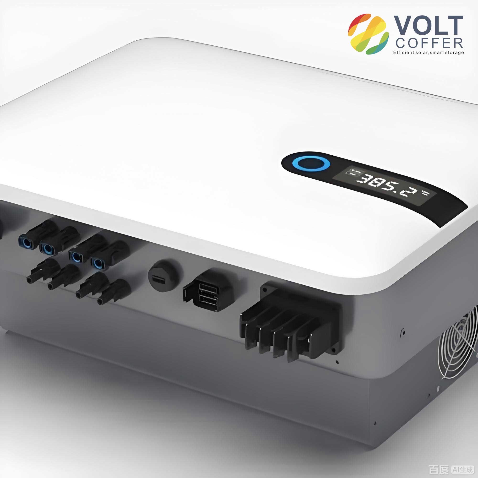
Traditional solutions for low-frequency harmonic mitigation include proportional-integral (PI) controllers in the synchronous reference frame and proportional-resonant (PR) controllers in the stationary frame. While effective for fundamental current tracking, PI controllers struggle with harmonic rejection. Multiple PR controllers can be paralleled to target specific harmonics, but this approach complicates system stability due to accumulated phase lag and increases computational burden. Repetitive control (RC) has emerged as a powerful alternative, embedding an internal model of periodic signals to provide theoretically infinite gain at all harmonic frequencies, thus ensuring zero steady-state error for periodic disturbances. However, the conventional RC’s internal model introduces a delay of one fundamental period, inherently trading off dynamic response speed for superb steady-state accuracy.
To address the specific need for suppressing dominant odd-order harmonics while improving convergence speed, the Odd-Harmonic Repetitive Controller (ORC) was developed. By modifying the internal model structure, the ORC provides high gain only at odd harmonic frequencies (fundamental, 3rd, 5th, etc.) and reduces the inherent delay to half of the fundamental period. This leads to faster error convergence and reduced memory requirements compared to conventional RC. Despite these advantages, the performance of the ORC is still limited by its half-period delay and its sensitivity to grid frequency variations, which detune the resonant peaks and degrade harmonic suppression. This analysis delves into a significant advancement: a Novel Odd-Harmonic Repetitive Control (N0RC) strategy featuring a modified internal model with a feedforward path. This strategy aims to fundamentally enhance the harmonic suppression characteristics and dynamic performance of a single-phase grid connected inverter.
Fundamentals of Traditional Odd-Harmonic Repetitive Control (0RC)
The core of any repetitive control strategy is its internal model. For a traditional 0RC, the discrete-time internal model is characterized by a delay of \(N/2\) samples, where \(N = f_s / f_0\) is the number of samples per fundamental period (\(f_s\) is sampling frequency, \(f_0\) is grid frequency). Its transfer function is given by:
$$ G_{orc}(z) = \frac{E_1(z)}{R(z)} = \frac{z^{-N/2}}{1 + Q(z)z^{-N/2}} $$
where \(R(z)\) is the reference input, \(E_1(z)\) is the error signal processed by the internal model, and \(Q(z)\) is typically a constant slightly less than 1 (e.g., 0.95) or a low-pass filter to enhance system stability. The term \(z^{-N/2}\) represents the half-period delay. The frequency response of this internal model shows peaks (infinite gain when \(Q(z)=1\)) at odd harmonic frequencies \(\omega_h = (2k+1)\omega_0\), where \(k=0,1,2,…\). The gain at these frequencies is derived from the limit:
$$ \lim_{\omega \to (2k+1)\omega_0} |G_{orc}(e^{j\omega T_s})| = \lim_{\omega \to (2k+1)\omega_0} \frac{1}{|1 + e^{-j\omega T_0/2}|} = \frac{1}{|1 + (-1)|} \to \infty $$
This confirms its action as a bank of resonant filters at odd harmonics. While an improvement, this structure’s performance is bounded by its fixed delay and finite bandwidth around resonant peaks, making the grid connected inverter susceptible to performance degradation during grid frequency drifts.
The Novel N0RC Strategy: Architecture and Mathematical Foundation
The proposed N0RC strategy introduces a pivotal modification to the internal model structure by incorporating a direct feedforward path for the error signal alongside the delayed feedback path. The continuous-time representation of the new internal model’s transfer function is:
$$ G_{n0rc}(s) = \frac{E_1(s)}{R(s)} = \frac{1 – Q(s)e^{-sT_0/2}}{1 + Q(s)e^{-sT_0/2}} $$
Setting \(Q(s)=1\) for ideal analysis yields:
$$ G_{n0rc}(s) = \frac{1 – e^{-sT_0/2}}{1 + e^{-sT_0/2}} $$
This expression can be manipulated to reveal its fundamental characteristic. Using the identity for the hyperbolic tangent function, it can be shown that:
$$ G_{n0rc}(s) = \tanh\left(\frac{sT_0}{4}\right) $$
However, a more intuitive and valuable form is obtained by rationalizing the expression. Multiplying numerator and denominator by \(e^{sT_0/4}\):
$$ G_{n0rc}(s) = \frac{e^{sT_0/4} – e^{-sT_0/4}}{e^{sT_0/4} + e^{-sT_0/4}} = \frac{2\sinh(sT_0/4)}{2\cosh(sT_0/4)} = \tanh\left(\frac{sT_0}{4}\right) $$
To understand its harmonic selectivity, consider the limit as \(s\) approaches the frequency of an odd harmonic, \(j(2k+1)\omega_0\):
$$ \lim_{s \to j(2k+1)\omega_0} e^{-sT_0/2} = e^{-j(2k+1)\pi} = -1 $$
Therefore,
$$ \lim_{s \to j(2k+1)\omega_0} G_{n0rc}(s) = \frac{1 – (-1)}{1 + (-1)} \to \infty $$
This confirms that the N0RC internal model also provides infinite gain (in the ideal case) at odd harmonic frequencies. Conversely, at even harmonic frequencies \(s \to j(2k)\omega_0\), \(e^{-sT_0/2} = e^{-j2k\pi} = 1\), leading to:
$$ \lim_{s \to j(2k)\omega_0} G_{n0rc}(s) = \frac{1 – 1}{1 + 1} = 0 $$
The N0RC internal model places zeros at even harmonic frequencies, actively attenuating any error components at these frequencies. A critical advancement is revealed in the gain magnitude comparison. Analyzing the discrete-time frequency response magnitude at an odd harmonic frequency \(\omega_h\):
$$ |G_{n0rc}(e^{j\omega_h T_s})| = \left| \frac{1 – e^{-j\omega_h T_0/2}}{1 + e^{-j\omega_h T_0/2}} \right| = \left| \frac{1 – (-1)}{1 + (-1)} \right| \text{(evaluating at limit)} $$
A more precise analysis near \(\omega_h\) shows the gain is significantly higher than that of the traditional 0RC. In fact, when \(Q(z)=1\), the magnitude ratio is:
$$ \frac{|G_{n0rc}(e^{j\omega T_s})|}{|G_{orc}(e^{j\omega T_s})|} \approx 2 \quad \text{as} \quad \omega \to \omega_h $$
This indicates that the N0RC provides approximately 6 dB higher gain at the target odd harmonic frequencies compared to the traditional 0RC, promising faster convergence and better harmonic suppression.
Frequency Characteristics and Bandwidth Analysis
The frequency response is the most direct way to visualize the superiority of the N0RC for a grid connected inverter. The Bode plot comparison between \(G_{n0rc}(z)\) and \(G_{orc}(z)\) (with \(Q=0.99\)) reveals two key advantages for the N0RC:
- Higher Resonant Gain: At the fundamental (50 Hz) and odd harmonic frequencies (150 Hz, 250 Hz, etc.), the magnitude peak of the N0RC internal model is notably higher than that of the 0RC.
- Wider Resonant Bandwidth: The -3 dB bandwidth around each resonant frequency is substantially broader for the N0RC.
This expanded bandwidth is crucial for the robustness of the grid connected inverter. In practical applications, the grid frequency \(f_0\) is not constant but fluctuates within a range (e.g., 49.5 Hz to 50.5 Hz). A controller with a narrow resonant peak would see its gain drop sharply if the grid frequency shifts away from the nominal value, degrading harmonic suppression. The N0RC’s wider bandwidth ensures that high gain is maintained over a larger frequency range around each odd harmonic, making the grid connected inverter system more robust to such grid frequency variations. This characteristic stems from the introduced zeros, which, according to Bode’s sensitivity integral, reshape the frequency response to trade off steeper roll-off at even harmonics for gentler, wider peaks at odd harmonics.
System Implementation, Stability, and Parameter Design for LCL-type Inverters
In practice, the N0RC internal model is incorporated into a composite controller to ensure stability and satisfactory dynamic response. The N0RC is typically placed in parallel with a proportional (P) controller. The P controller improves transient response and stabilizes the plant, while the N0RC ensures zero steady-state error for odd harmonic disturbances. The complete discrete-time control block diagram for a single-phase grid connected inverter includes several key components:
$$ D(z) = k_p + \underbrace{\frac{k_r z^{-(N/2 – m)} S(z)}{1 – Q(z)z^{-N/2}}}_{G_{n0rc}(z) \text{ with compensators}} $$
where:
- \(k_p\) is the proportional gain.
- \(k_r\) is the N0RC gain.
- \(z^{m}\) is a phase lead compensator to counteract the phase lag of the plant and filters.
- \(S(z)\) is a low-pass filter (e.g., a 4th-order Butterworth) to attenuate high-frequency noise and ensure stability by rolling off the gain near the Nyquist frequency.
- \(Q(z)\) is a constant (e.g., 0.95) to provide a stability margin.
The controlled plant \(P(z)\) is the discrete-time model of the LCL filter and inverter bridge. For an LCL-type grid connected inverter with inverter-side inductance \(L_1\), grid-side inductance \(L_2\), filter capacitance \(C\), and possible passive damping resistor \(R_d\), the continuous-time transfer function from inverter output voltage to grid current is:
$$ P(s) = \frac{i_g(s)}{u_{inv}(s)} = \frac{1}{L_1 L_2 C s^3 + (L_1+L_2)R_d C s^2 + (L_1+L_2)s} $$
This model is discretized using a Zero-Order Hold (ZOH) method to obtain \(P(z)\).
The stability analysis of the closed-loop system with the N0RC controller requires careful consideration. The characteristic equation of the system is more complex than that with a standard RC due to the modified internal model. A sufficient stability criterion can be derived using the Small Gain Theorem. The system is stable if:
- All poles of the modified plant \(P_0(z) = P(z)/(1 + k_p P(z))\) are inside the unit circle.
- The following magnitude condition holds for all frequencies \(\omega \in [0, \pi/T_s]\):
$$ |H(e^{j\omega T_s})| = \left| Q(e^{j\omega T_s}) \left( 1 – \frac{k_r z^{-(N/2 – m)} S(z) P_0(z)}{1 + Q(z)z^{-N/2}} \right)^{-1} \right| < 1 $$
This condition essentially requires the magnitude of the open-loop transfer function seen by the periodic signal generator to be less than 1 at all frequencies.
Parameter design follows a systematic procedure:
- Proportional Gain (\(k_p\)): Designed to stabilize the plant \(P(z)\) and achieve a fast dynamic response for the inner loop. It is chosen to place the poles of \(P_0(z)\) well within the unit circle.
- Internal Model Constant (\(Q\)): Chosen as a constant (e.g., 0.95) close to 1 to maintain high gain at harmonics while ensuring stability robustness.
- Low-Pass Filter (\(S(z)\)): Designed with a cutoff frequency (e.g., 1 kHz) above the highest harmonic to be suppressed but below the Nyquist frequency to provide sufficient attenuation at high frequencies.
- Phase Lead Compensator (\(m\)): The integer \(m\) is chosen such that the phase of \(S(z)P_0(z)z^{m}\) is close to zero in the low-frequency range (below the filter cutoff). This is found by inspecting the phase plot of \(S(z)P_0(z)\).
- Repetitive Gain (\(k_r\)): This is the final tuning parameter. It is maximized within the bounds set by the stability condition (2) above to achieve the fastest possible harmonic rejection without causing instability. The maximum allowable \(k_r\) can be estimated from the peak magnitude of \(S(z)P_0(z)z^{m}\) and the value of \(Q\).
| Feature | Traditional 0RC | Proposed N0RC |
|---|---|---|
| Internal Model Structure | $$ G_{orc}(z) = \frac{z^{-N/2}}{1 + Q z^{-N/2}} $$ | $$ G_{n0rc}(z) = \frac{1 – Q z^{-N/2}}{1 + Q z^{-N/2}} $$ |
| Inherent Delay | \(T_0/2\) | \(T_0/2\) |
| Gain at Odd Harmonics | High (Theoretically infinite when Q=1) | Very High (Approx. 2x or +6dB higher than 0RC) |
| Zeros | None in basic structure | At even harmonic frequencies |
| Resonant Bandwidth | Standard | Wider |
| Robustness to Grid Freq. Variation | Moderate | Superior |
| Error Convergence Speed | Faster than full-period RC | Fastest among RC variants |
| Memory Requirement (Samples) | \(N/2\) | \(N/2\) |
| Dynamic Response to Step Changes | Good | Excellent |
Performance Evaluation and Comparative Summary
The theoretical advantages of the N0RC translate into tangible performance benefits for the grid connected inverter. Experimental validations on a single-phase LCL-type grid connected inverter platform consistently demonstrate the following outcomes when compared to a traditional parallel P+0RC scheme:
- Lower Total Harmonic Distortion (THD): Under nominal grid frequency (50 Hz), the N0RC-controlled inverter output current exhibits a lower THD. The harmonic spectrum shows significantly reduced magnitudes at the 3rd, 5th, 7th, and other odd harmonics.
- Enhanced Robustness Under Frequency Fluctuation: When the grid frequency deviates (e.g., to 49.6 Hz or 50.4 Hz), the performance gap widens. The THD of the current under 0RC control increases noticeably as its narrow resonant peaks become detuned. In contrast, the N0RC-controlled system maintains a much lower THD due to its wider bandwidth, which keeps high gain effective over the frequency deviation range.
- Superior Dynamic Response: During transient events, such as a step change in the reference current amplitude, the N0RC system settles to the new steady-state faster than the 0RC system. This is a direct consequence of its higher gain at the fundamental frequency, leading to a faster correction of the tracking error.
The N0RC strategy, therefore, represents a comprehensive enhancement for controlling a grid connected inverter. It successfully addresses the triple challenge of achieving excellent steady-state accuracy (very low odd-harmonic content), maintaining this performance under realistic grid conditions (frequency variations), and providing a responsive dynamic performance. The modified internal model with its feedforward path is a key innovation that reshapes the frequency response favorably without increasing the memory footprint or fundamental delay compared to the 0RC. This makes the N0RC a highly attractive and practical control solution for modern single-phase and potentially three-phase grid connected inverter systems where power quality and grid compliance are critical.