
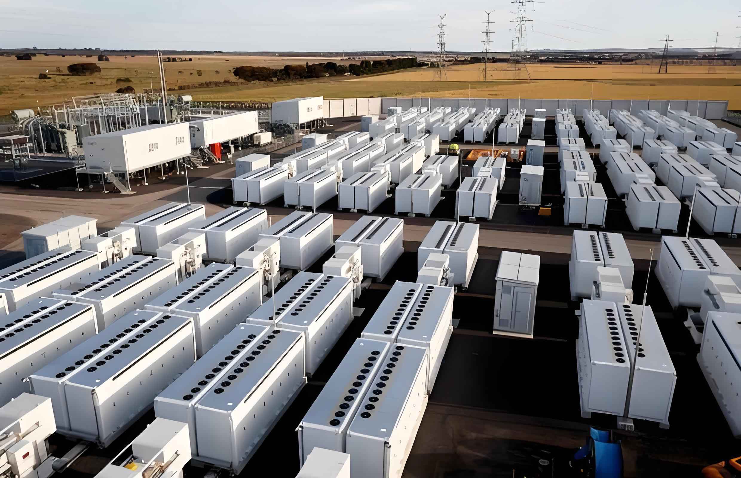
With the rapid growth of renewable energy integration, electrochemical energy storage systems have become critical flexibility resources in modern power grids. Containerized energy storage power stations, characterized by high energy density and modular design, rely heavily on efficient thermal management to ensure operational safety and longevity of energy storage batteries. This study proposes a centralized refrigeration station coupled with water thermal energy storage to optimize cooling efficiency and reduce energy consumption in air conditioning systems.
1. Thermal Load Calculation and Energy Analysis
The cooling load of containerized energy storage battery systems consists of three components:
1.1 Heat Generation from Battery Operation
The heat generated by energy storage batteries during charge/discharge cycles is calculated as:
$$ P_1 = n_1 I^2 R \times 1.2 \times 10^{-3} $$
where \( P_1 \) = heat load (kW), \( n_1 \) = number of battery cells, \( I \) = current (A), and \( R \) = cell internal resistance (Ω).
1.2 Envelope Heat Transfer
Heat transfer through container walls is expressed as:
$$ P_2 = KA \Delta T_1 \times 10^{-3} $$
where \( K \) = thermal conductivity (W/m²·K), \( A \) = surface area (m²), and \( \Delta T_1 \) = temperature difference (K).
1.3 Auxiliary Equipment Heat
Heat from fans/pumps is quantified as:
$$ P_3 = n_2 p $$
where \( n_2 \) = number of auxiliary devices and \( p \) = power per device (kW).
The total cooling requirement is:
$$ P_5 = k(P_1 + P_2 + P_3 + P_4) $$
where \( P_4 \) = heat absorbed by battery temperature rise and \( k \) = safety factor (1.2–1.5).
2. Optimized Cooling System Design
The proposed system integrates water-cooled chillers, cooling towers, and thermal storage tanks to leverage off-peak electricity pricing:
| Component | Air-Cooled System | Liquid-Cooled System |
|---|---|---|
| Chillers | 2×1478 kW COP 5.5 | 2×1700 kW COP 5.5 |
| Thermal Storage | 342 m³ tank | 438 m³ tank |
| Pumps | 3×22 kW (chilled water) | 3×30 kW (chilled water) |
| Cooling Tower | 2×350 m³/h | 2×400 m³/h |
Four operational modes are implemented:
- Direct Chilling: Active during off-peak hours
- Free Cooling: Utilizes cooling towers when ambient wet-bulb temperature ≤10°C
- Thermal Charging: Stores chilled water during low electricity rates
- Thermal Discharging: Releases stored cooling during peak demand
3. Performance Comparison
Case studies of two 100 MW/200 MWh projects demonstrate significant improvements:
| Parameter | Air-Cooled System | Liquid-Cooled System |
|---|---|---|
| Original Consumption | 1.6358 GWh | 1.2384 GWh |
| Optimized Consumption | 0.7553 GWh (-53.8%) | 0.8527 GWh (-31.1%) |
| Off-Peak Utilization | 85.7% | 86.5% |
The energy shift to low-tariff periods follows:
$$ \text{Off-peak Ratio} = \frac{E_{\text{off-peak}}}{E_{\text{total}}} \times 100\% $$
where \( E_{\text{off-peak}} \) = energy consumed during discounted electricity periods.
4. Economic Impact
For a typical Shandong Province electricity market with peak/off-peak rates of ¥1.20/0.40 per kWh:
$$ \text{Annual Savings} = (E_{\text{original}} – E_{\text{optimized}}) \times (\Delta \text{Tariff}) $$
Implementation reduces operating costs by 42–58% while maintaining energy storage battery temperatures within 23±2°C.
5. Conclusion
The integration of water thermal energy storage with centralized chilling systems significantly improves the economic and operational efficiency of containerized energy storage battery facilities. Future work will explore advanced airflow optimization and hybrid cooling strategies to further enhance performance.