
The widespread adoption of solar panels as a key component of distributed energy systems brings to the forefront critical structural challenges, with wind-induced failures being a primary concern for both ground-mounted and rooftop installations. A significant factor contributing to such damage is the lack of refined wind load specifications, particularly concerning the distribution models used in the structural design of the solar panels and their supporting frameworks. Current design codes often prescribe simplified, uniform wind pressure coefficients, which fail to capture the complex aerodynamic behavior and the resulting bending moments that can critically stress the support structure. This investigation, based on detailed wind tunnel pressure testing, aims to bridge this gap by analyzing the actual pressure distribution on solar panels and proposing improved wind load models that account for panel inclination and the significant influence of wind-induced moments.
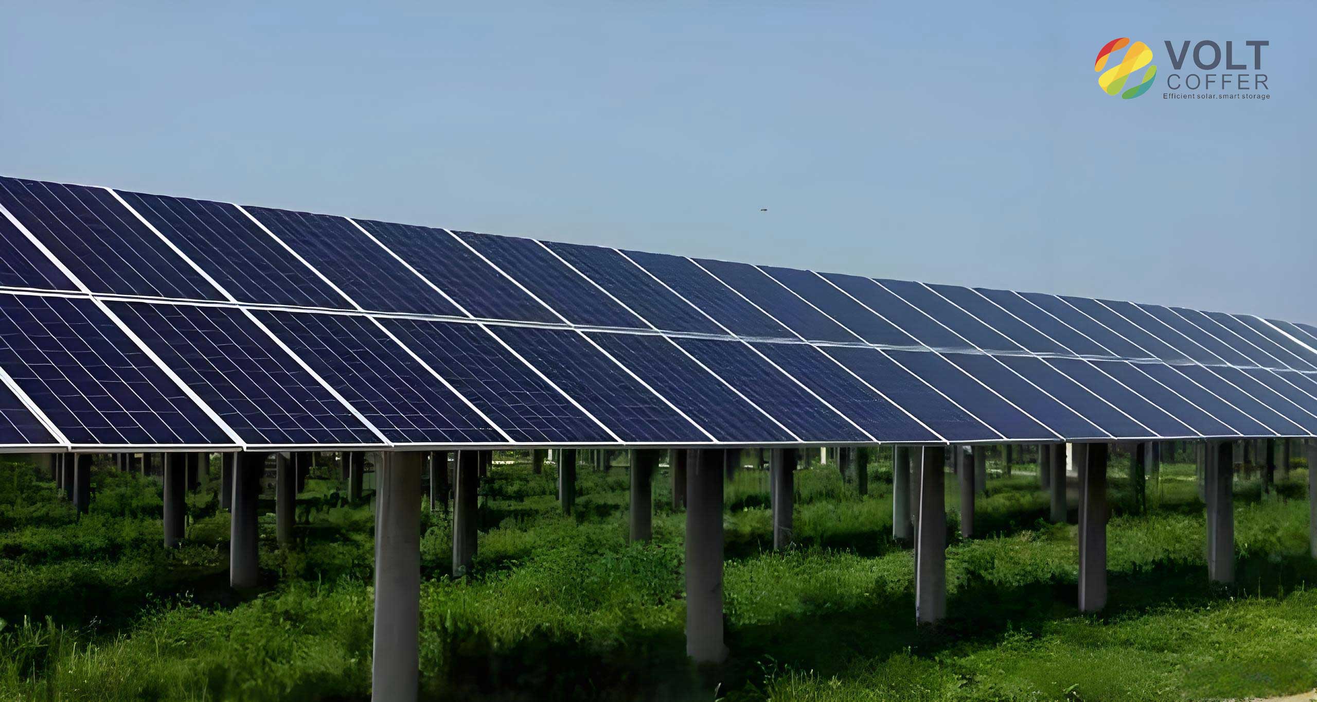
The foundation of this study is a series of rigid model pressure tests conducted in a low-turbulence uniform flow wind tunnel. The test model, representing a common solar panel configuration, was constructed at a geometric scale of 4:1. The model featured a comprehensive array of 240 pressure taps distributed across its upper and lower surfaces, allowing for a high-resolution mapping of the wind pressure field. The solar panel’s inclination angle, denoted by $\beta$, was systematically varied across six configurations: 5°, 10°, 20°, 30°, 40°, and 55°. For each inclination, the wind direction angle $\alpha$ was rotated from 0° to 180° in 15° increments, capturing the full range of potential wind attack angles on the solar panels. The primary measured parameter is the instantaneous pressure coefficient at each tap, which is converted into a shape coefficient, $\mu_s(t)$, representing the non-dimensional wind load. The mean shape coefficient for a point i is defined as:
$$
\mu_{si} = \frac{P_{wi} – P_{ni}}{0.5 \rho U^2}
$$
where $P_{wi}$ and $P_{ni}$ are the mean pressures on the windward and leeward surfaces at point i, respectively, $\rho$ is the air density, and $U$ is the reference mean wind velocity. To assess the global wind load effects, integrated force and moment coefficients are calculated from the distributed pressures. The overall shape coefficient $\mu_s$, the bending moment coefficient about the panel’s short axis $C_{Mx}$, and the bending moment coefficient about its long axis $C_{My}$ are defined as follows:
$$
\mu_s = \frac{\sum_{i=1}^{m} \mu_{si} A_i}{B L}
$$
$$
C_{Mx} = \frac{\sum_{i=1}^{m} \mu_{si} A_i y_i}{B L^2}
$$
$$
C_{My} = \frac{\sum_{i=1}^{m} \mu_{si} A_i x_i}{B^2 L}
$$
Here, $A_i$ is the tributary area of measurement point i, while $x_i$ and $y_i$ are its coordinates relative to the panel’s centroid, with $B$ and $L$ being the panel’s width and length, respectively. These global coefficients are crucial for understanding the net force and the twisting effects on the mounting structure of the solar panels.
The analysis of the measured pressure data reveals that the wind load distribution on solar panels is highly non-uniform and complex. For critical wind directions ($\alpha = 0^\circ$ and $180^\circ$), where the global wind load is often maximum, a strong gradient in the shape coefficient is observed along the panel’s length. For instance, with a panel tilt of $\beta = 30^\circ$, the shape coefficient at the windward edge can be up to four times greater than at the leeward edge. This gradient is responsible for generating substantial bending moments. Oblique wind directions ($\alpha = 30^\circ$, $150^\circ$, etc.) produce complex, three-dimensional pressure patterns with gradients along both the length and width of the solar panels, leading to combined biaxial bending. These patterns cannot be accurately represented by a uniform or simple two-zone load distribution, highlighting a fundamental shortcoming in some conventional design approaches for solar panels.
The contour plots of the global coefficients provide a complete picture of the wind load susceptibility of solar panels. The maximum positive overall shape coefficient $\mu_s$ (pushing the panel down) increases with panel inclination, reaching values near 1.3 for steeper angles. Conversely, the maximum negative $\mu_s$ (suction lifting the panel up) peaks at a moderate inclination around $45^\circ$, reaching values as high as -1.6, which is more severe than values suggested in some current design standards for solar panels. More importantly, the bending moment coefficients $C_{Mx}$ and $C_{My}$ show that significant twisting actions are common. The moment about the short axis is particularly critical, with its largest negative value (tending to overturn the panel) occurring concurrently with the maximum suction at high inclinations. The moment about the long axis, though generally smaller, can be significant under oblique winds. Ignoring these moments in the design of supports for solar panels can lead to underestimation of stresses and connection forces.
| Inclination $\beta$ | $\mu_{s1}$ (Positive) | $\mu_{s2}$ (Negative) |
|---|---|---|
| 5° | 0.10 | -0.50 |
| 10° | 0.25 | -0.65 |
| 20° | 0.60 | -1.00 |
| 30° | 1.00 | -1.30 |
| 40° | 1.20 | -1.60 |
| 55° | 1.30 | -1.40 |
To address the limitations of uniform load models, a more physically representative “Four-Corner Planar Distribution Model” is proposed. This model assumes the pressure distribution on the solar panel can be approximated by a plane defined by shape coefficients at its four corners ($\mu_A$, $\mu_B$, $\mu_C$, $\mu_D$). These four unknown coefficients are solved by ensuring equivalence with the three measured global load effects: net force, moment about the short axis, and moment about the long axis. The system of equations is:
$$
\begin{bmatrix}
1 & -1 & 1 & -1 \\
1 & 1 & 1 & 1 \\
1 & -1 & -1 & 1 \\
1 & 1 & -1 & -1
\end{bmatrix}
\begin{bmatrix}
\mu_A \\ \mu_B \\ \mu_C \\ \mu_D
\end{bmatrix}
=
\begin{bmatrix}
0 \\ 4\mu_s \\ 24C_{Mx} \\ 24C_{My}
\end{bmatrix}
$$
The solution provides a simple, planar approximation of the load on the solar panels that inherently includes the effects of both bending moments. For the critical wind directions ($\alpha = 0^\circ$ and $180^\circ$), this model simplifies further. Analysis shows that for these cases, $\mu_A \approx \mu_B$ and $\mu_C \approx \mu_D$, meaning the pressure distribution is essentially trapezoidal along the panel’s length. This validates the concept of a trapezoidal load model for the design of solar panels under worst-case wind scenarios, effectively accounting for the dominant bending moment about the short axis.
| Inclination $\beta$ | $\mu_{w1}$ (Windward Edge) | $\mu_{l1}$ (Leeward Edge) | $\mu_{w2}$ (Windward Edge) | $\mu_{l2}$ (Leeward Edge) |
|---|---|---|---|---|
| 5° | 0.00 | 0.20 | -1.20 | 0.20 |
| 10° | 0.40 | 0.10 | -1.35 | 0.15 |
| 20° | 0.90 | 0.30 | -2.10 | 0.10 |
| 30° | 1.65 | 0.35 | -2.40 | -0.20 |
| 40° | 1.90 | 0.50 | -2.80 | -0.40 |
| 55° | 1.80 | 0.80 | -2.00 | -0.80 |
An alternative and highly practical model is the “Eccentricity Model.” This approach retains the simplicity of a single resultant force (using the overall shape coefficient $\mu_s$) but accounts for load non-uniformity by applying this force at an eccentric location. The eccentricities $X_C$ and $Y_C$ from the centroid along the width and length, respectively, are derived directly from the global moment coefficients:
$$
\frac{X_C}{B} = \frac{C_{My}}{\mu_s}, \quad \frac{Y_C}{L} = \frac{C_{Mx}}{\mu_s}
$$
This model is particularly useful for the structural design of discrete supports or columns for solar panels, as it directly provides the additional moment demand ($\mu_s \times$ eccentricity) that must be resisted. The eccentricity, especially in the length direction $Y_C/L$, is significant and varies with inclination. For instance, under strong suction on a steep panel, the eccentricity can be around 0.13-0.17 of the panel length, representing a substantial overturning effect that must be considered in the foundation design for solar panels.
| Inclination $\beta$ | Positive Load Case | Negative Load Case | ||
|---|---|---|---|---|
| $\mu_{s1}$ | $Y_C/L$ | $X_C/B$ | $\mu_{s2}$ | $Y_C/L$ | $X_C/B$ | |
| 5° | 0.10 | 0.31 | 0.01 | -0.50 | 0.17 | 0.10 |
| 10° | 0.25 | 0.07 | 0.09 | -0.65 | 0.16 | 0.15 |
| 20° | 0.60 | 0.03 | 0.09 | -1.00 | 0.15 | 0.12 |
| 30° | 1.00 | 0.01 | 0.09 | -1.30 | 0.14 | 0.08 |
| 40° | 1.20 | 0.01 | 0.09 | -1.60 | 0.13 | 0.06 |
| 55° | 1.30 | 0.02 | 0.08 | -1.40 | 0.06 | 0.06 |
Based on the preceding analysis, three distinct wind load models are recommended for the structural design of solar panels, each with a specific use case. The Uniform Distribution Model (Table 1) provides a simple, conservative-for-net-force estimate of the overall shape coefficient that varies with inclination. It is an improvement over codes that use a single value for all solar panels but does not account for bending moments. The Trapezoidal Distribution Model (Table 2) offers a more refined approach. By specifying different shape coefficients for the windward and leeward edges of the solar panels, it implicitly incorporates the dominant bending moment about the short axis and provides a realistic approximation of the pressure distribution shape. This model is well-suited for designing beams, purlins, or frames supporting the solar panels along their edges.
Finally, the Eccentricity Model (Table 3) is the most direct method for designing discrete support points, such as central posts or column bases for solar panel arrays. It combines the net force with explicit eccentricities that induce design moments. For typical support configurations of solar panels, the trapezoidal model is often sufficient as the moment about the short axis is the most critical. However, for support layouts sensitive to biaxial bending, the eccentricity model should be applied, checking both directional moments separately. It is crucial to note that the values provided in the tables correspond to the most severe load case for each inclination, which has been aligned with the $0^\circ$ or $180^\circ$ wind direction for design simplicity, even if the absolute maximum in some cases occurs at a slightly different angle for solar panels at very low inclinations.
In conclusion, the wind loading on solar panels is characterized by significant pressure gradients that generate substantial bending moments, which are often overlooked in simplified design codes. The uniform load model, while improved with inclination-specific coefficients, remains incomplete. For robust and economical design of solar panel support structures, it is strongly recommended to adopt load models that account for these moments. The trapezoidal distribution and the eccentricity models presented here, derived from rigorous wind tunnel testing, provide practical and physically sound methodologies to achieve this goal, thereby enhancing the wind resilience of solar energy systems. Future work should focus on validating these models against the structural response of various support types and extending the analysis to interactive effects within multi-panel arrays of solar panels.