1. Topology structure
The study focuses on modular multilevel converter-battery energy storage system in medium voltage DC distribution networks. The structure of the medium voltage DC distribution network system is shown in Figure 1 (a), where modular multilevel converter-battery energy storage system flexibly interconnects the medium voltage DC distribution network with the medium voltage AC power grid, achieving bidirectional flexible power transmission; The AC/DC microgrid composed of distributed power sources, flexible loads, etc. is connected to the medium voltage DC bus through interconnected converters.
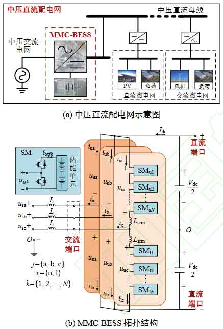
The modular multilevel converter-battery energy storage system topology is shown in Figure 1 (b), where each phase consists of two bridge arms, upper and lower, and bridge arm inductors. Each bridge arm is cascaded by N submodules. This article mainly analyzes the half bridge modular multilevel converter-battery energy storage system as an example. The energy storage unit composed of lithium batteries is connected in parallel on the DC side of the submodule. In the figure, Vdc is the DC voltage, usj (j=a, b, c) is the AC grid phase voltage, uj is the equivalent output voltage of modular multilevel converter-battery energy storage system, ij is the output current, uuj and ulj are the upper and lower bridge arm voltages, iuj and ilj are the upper and lower bridge arm currents, L is the grid side filtering inductance, Larm is the bridge arm inductance, uxjk is the output voltage of the submodule (x=u, l; k=1, 2,…, N), ibxjk is the current of the energy storage unit.
2. Mathematical models
Considering the symmetry between the AC power grid and MMC under normal operating conditions, this article only analyzes phase a as an example. In order to achieve power balance between the AC and DC sides of modular multilevel converter-battery energy storage system and its internal battery, it is necessary to meet the following requirements:
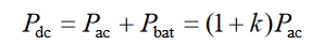
In the formula, Pac represents the AC power of modular multilevel converter-battery energy storage system; Pdc represents the DC side power of modular multilevel converter-battery energy storage system; Pbat represents the sum of power of the modular multilevel converter-battery energy storage system battery pack; K represents the ratio of battery power Pbat to AC power Pac, which is defined in this article as the proportion of energy storage power.
Ignoring the voltage drop on the bridge arm inductance, based on the reference direction in Figure 1 and Kirchhoff’s voltage/current law, it can be concluded that:
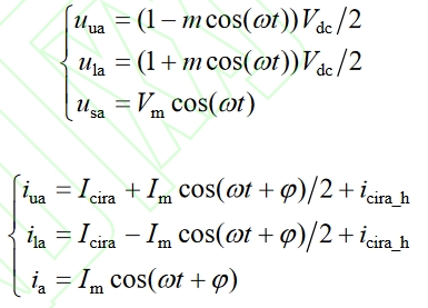
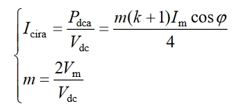
In the formula, Vm is the amplitude of phase a voltage; Im is the amplitude of phase A current; φ Is the power factor angle; Icira_ H is the harmonic component of the circulating current, Icira and m are the DC component and modulation ratio of the A-phase circulating current, respectively, and their expressions are:
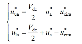
Based on the modular multilevel converter-battery energy storage system AC and DC equivalent circuit model, establish its AC and DC circuit equations as follows:
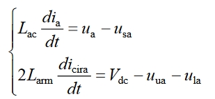
In the formula, ua=(ula uua)/2 represents the equivalent AC output voltage; Lac=L+Larm/2, is the AC equivalent inductance. The modular multilevel converter-battery energy storage system AC current and circulating current can be decoupled and controlled separately through the voltage difference and voltage sum of the lower and upper bridge arms. According to the modular multilevel converter-battery energy storage system AC and DC circuit control equations in the above equation, the bridge arm voltage reference value can be expressed as: