
With the continuous reduction of reserves of traditional fossil fuels such as crude oil and coal, and the increasing environmental pollution caused by the use of fossil fuels, the greenhouse effect and air pollution are the most prominent, especially the reduction of biodiversity caused by the greenhouse effect and the frequent occurrence of extreme weather, which pose a serious challenge to the sustainable development of the Earth. Therefore, vigorously developing clean and renewable energy has become a topic of common concern for countries around the world, and replacing traditional fossil fuels with clean energy is the future trend of world energy development. The unique advantages of solar energy in clean energy make it a hot topic for research and exploration.
Solar energy has abundant reserves and is easy to obtain, with no pollution emissions during use, so the application prospects of solar energy are very optimistic. The way of life and production in today’s society is increasingly reliant on electricity. Compared with traditional power generation methods such as thermal power, hydropower, and engine power generation, solar power generation has many advantages, such as inexhaustible supply, easy access, safety and reliability, low failure rate, short installation cycle, high energy transfer efficiency, high degree of intelligence, and no geographical restrictions on equipment installation. Moreover, due to its pollution-free and noiseless nature, it can be widely distributed, It does not need to be concentrated in a certain area over long distances, and can overcome problems such as excessive losses in traditional long-distance power transmission lines.
The working process of a photovoltaic inverter system is to convert the direct current generated by the photovoltaic cell into qualified alternating current and provide it to electrical appliances or grid connection. Due to the many shortcomings of traditional two-level solar inverters in high-power working environments, such as high switching losses and high voltage change rates, they are prone to insulation layer aging or breakdown when subjected to inductive loads, causing electrical safety hazards and generating a large amount of electromagnetic interference. The multi-level inverter structure can effectively solve the above problems, and currently the most widely used is the three-level solar inverter. The multi-level inverter strategy can effectively improve energy utilization efficiency and improve production efficiency and product quality in industrial production.
Regarding solar photovoltaic inverters, how to improve efficiency has become a hot topic of concern. Improving the conversion efficiency of solar inverters means less dependence on other energy sources, which will bring huge improvements to the human living environment. This is mainly reflected in the slowing down of the greenhouse effect, which has a very positive impact on protecting species diversity and building a community with a shared future for mankind. At the same time, with the introduction of policies encouraging photovoltaic power generation in various countries, Higher inverter efficiency also means higher economic benefits. At present, improving the conversion efficiency of solar photovoltaic inverters mainly starts from two aspects: system hardware and modulation strategy. The system hardware mainly manifests in the selection of circuit topology and power electronic components, and the corresponding modulation strategy also has an important impact on the efficiency and output voltage quality of solar inverters.
1. Current application status of solar power generation both domestically and internationally
At present, the total installed capacity of solar power generation accounts for a very low proportion among all power generation methods, and its primary constraint is the high initial installation cost. With the development of the photovoltaic industry, the manufacturing cost of photovoltaic products is reduced and the power generation efficiency is improved, and photovoltaic power generation will be increasingly recognized. Since 2011, countries such as China, the United States, Japan, and Germany have increased their investment in the field of photovoltaic power generation, becoming the main photovoltaic power generation regions in the world. In 2019, the total installed capacity of new photovoltaic systems worldwide was 98 GW, with a cumulative total installed capacity of 580.1 GW.
In the past decade or so, the photovoltaic product market in the United States has expanded at an average annual rate of 39%, ranking fourth in the world in terms of total installed capacity. The United States has launched a series of photovoltaic development plans, such as the Obama Energy Plan and ITC, and is expected to achieve a total photovoltaic power generation of 10% of all electricity demand by 2020, with an estimated total installed capacity of 300 GW. The photovoltaic technology industry will provide approximately 680000 related jobs to the United States, and can reduce carbon dioxide emissions by 380 million tons annually. At the same time, the United States has excellent technical support and policy incentives in photovoltaic power generation, so the scale of this energy industry will continue to expand.
In response to the high cost of photovoltaic power generation and the difficulty of grid connection, Germany has implemented policies such as grid connection subsidies through legislation to promote the development of the photovoltaic industry. In May 2012, the installed capacity of photovoltaic power generation in Germany reached 21 GW, accounting for approximately 40% of the country’s electricity consumption. Subsequently, EU countries also introduced relevant technical indicators and industry standards, providing a solid foundation for photovoltaic grid connected power generation.
Japan is the main market for photovoltaic products in Asia. Since the oil crisis in the late 1970s, it has been seeking renewable energy to improve the structure of traditional fossil fuels and reduce dependence on fossil fuels. Relying on Japan’s strong economic strength and leading semiconductor technology, its photovoltaic power generation system industry market has gradually matured and grown in scale. Its goal for photovoltaic power generation applications is very clear, with an expected cumulative installed capacity of 28.7 GW by 2020, and the production cost of solar cells is controlled at 75 yen per watt.
China is rich in solar energy resources. More than 2/3 of China’s land area is rich in solar energy resources, especially the Xizang Plateau, which represents the northwest region with the highest total radiation. However, the application of photovoltaic power generation in China started late. In 2002, China began to catch up with Europe, America and other regions in the field of photovoltaic power generation technology. In 2010, China’s photovoltaic industry began to rise and became the backbone of the global photovoltaic industry development. In 2019, China’s cumulative installed capacity reached 204.3 GW, with an additional 30.1 GW, ranking first in the world for seven consecutive years. This indicates that China attaches great importance to the development and utilization of solar energy.
It can be seen that photovoltaic power generation technology has become an important way to provide electricity demand at present. At the same time, with strong support from government policies and updates in power electronics technology, the cost of photovoltaic power generation will continue to decrease, and its proportion in the energy structure will continue to increase. Therefore, the application market of photovoltaic power generation is very optimistic.
2. Introduction to Solar Power Generation Systems
Solar power generation systems convert solar energy into electrical energy for use by electrical appliances or grid connection. Therefore, according to this characteristic, they can be divided into independent solar power generation systems and grid connected solar power generation systems.
Independent solar power generation systems are mainly concentrated in remote areas far from the power grid, such as mountainous areas, islands, street lighting, and communication base stations. Due to cost constraints in installing transmission equipment and high transmission losses, their main purpose is to solve power supply problems.
The photovoltaic array first converts solar radiation energy into direct current energy. Under the control of the main control circuit, it is converted into voltage stable direct current to charge the battery, or output alternating current through the solar inverter for use by the load. Due to the significant impact of light intensity on photovoltaic power generation, such as cloudy days, insufficient light intensity in the morning and evening, buildings or leaf cover, the output power of the photovoltaic array is low during this period, so an energy storage module is necessary. When the photovoltaic power generation exceeds the load power, electrical energy can be stored through energy storage modules, among which batteries are often used as photovoltaic energy storage modules due to their low cost and simple use. The main function of the main control circuit is to track the maximum power point, control the output of the solar inverter, and control the charging and discharging of the battery.
The structure of grid connected photovoltaic power generation system is generally similar to that of independent photovoltaic power generation system. Both systems provide direct current obtained from photovoltaic arrays to electrical appliances through solar inverters. However, when the power of the electrical appliances is less than the output power of the photovoltaic cell array, the inverter output is connected in parallel with the power grid, achieving energy sharing and improving solar energy utilization. As there is no need for batteries to store energy, a large amount of volume and cost is saved.
2.1 Photovoltaic array system
A photovoltaic array refers to a battery module that encapsulates the smallest photovoltaic cell units in series or parallel to form a high-power output. Photovoltaic cells are semiconductor materials that function to convert solar energy into electrical energy.
When sunlight radiates onto the PN junction of semiconductor materials, if the photon energy is greater than its bandgap energy, a portion of electrons in the valence band will transition to the conduction band. At the same time, under the action of its internal electric field, the P region will attract the directional movement of photo generated holes generated in the N region, and the N region will attract the directional movement of photo generated electrons in the P region. Therefore, a large amount of positive charges will accumulate in the P region, and a large amount of negative charges will accumulate in the N region, forming a photo generated electromotive force. If a load is connected outside the PN junction, a current loop can be formed.
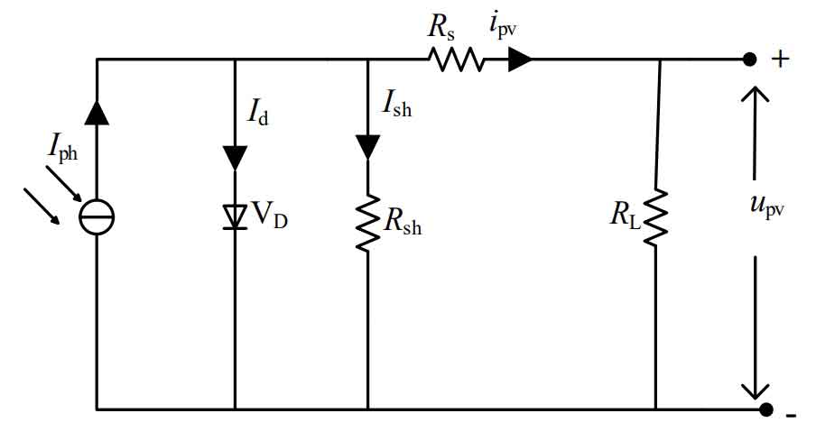
Photovoltaic cells can be seen as circuits composed of a current source, diodes, and equivalent series parallel resistors. In Figure 1, Rs is equivalent to the series resistance of the output path. As the photovoltaic cell is prone to leakage current during use, a resistor Rsh is equivalently connected in parallel at both ends. Iph is the photocurrent generated by the photovoltaic cell after being exposed to solar radiation, and its strength is related to the intensity of sunlight, the temperature of the external environment, and the material properties of the photovoltaic cell, regardless of the type of load and parameters, It is generally regarded as a constant current source. The potential difference upv formed by the photocurrent at both ends of the load RL biases the PN junction of the diode VD forward, which generates a bias current Id. In an ideal state, the bias current of the diode VD can be expressed as:
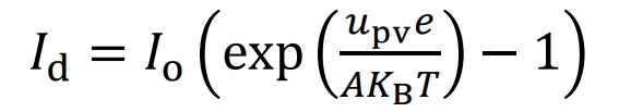
Io is the reverse saturation current of the PN junction; E is the charge value of the electron 1.6 × 10⁻¹⁹ C; A is the curve coefficient of the PN junction, which reflects the inherent characteristics and manufacturing process of the semiconductor material, and its value range is generally between 1 and 2; KB is the Boltzmann constant, 1.38X10 ^ -23 J/K; Tk is the absolute temperature of the surface of the photovoltaic cell.
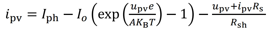
According to Figure 1 and the formula, the current output expression of the photovoltaic cell can be written:
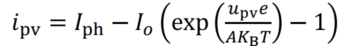
For most photovoltaic cells, the equivalent series resistance Rs is close to zero, while the equivalent parallel resistance Rsh has a relatively large resistance value. For ease of calculation, in an ideal state, the resistance Rs is considered zero and the resistance Rsh is considered infinite. Therefore, the formula can be simplified as follows:
Based on the relationship between the output voltage and current of photovoltaic cells, write the expression for their output power characteristics:
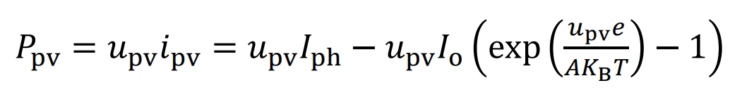
Draw a graph of the relationship between the output power Ppv and the output voltage upv of a photovoltaic cell, while the solar radiation intensity and the outer surface temperature remain constant:
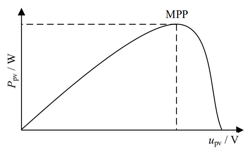
As the output voltage of photovoltaic cells increases, their output power will first increase and then decrease. Therefore, when environmental factors are determined, photovoltaic cells have a maximum power point. In order to improve the utilization of solar energy, it is generally necessary to control its output voltage at the maximum power point. When the external environment changes, such as changes in light intensity and temperature, it will directly affect the output voltage at its maximum power point.
2.2 Solar inverter system
A solar inverter is a power electronic device composed of controlled semiconductor switching devices. Its main function is to convert the direct current output from photovoltaic cells into regular sinusoidal alternating current for use by electrical appliances or grid connection. In photovoltaic power generation, single-phase solar inverters are generally not used, but three-phase solar inverters are used. Due to the variable output power of single-phase solar inverters, their power may sometimes be zero, which does not match the output power of photovoltaic cells. Large capacity electrolytic capacitors are needed to store energy when the output power of single-phase solar inverters is low. Due to the large volume and certain service life of electrolytic capacitors, This will undoubtedly increase design costs and system maintenance difficulties, and the output power of three-phase solar inverters is a constant value, which can well match the output power of photovoltaic cells. The solar inverter is mainly composed of switching tubes, which are generally selected as IGBT in high-power situations. By controlling the duty cycle of the corresponding switching tubes to change in a sinusoidal pattern, a sinusoidal waveform can be obtained.
Common solar inverters can be divided into voltage type solar inverters and current type solar inverters based on the type of DC input. Due to the parallel connection of a large capacitor on the DC side of a voltage type solar inverter, its DC voltage can be considered as a constant voltage source, with simple control and good dynamic performance. Therefore, voltage type solar inverters are commonly used in daily industrial applications. Voltage type solar inverters can be divided into two-level and multi-level solar inverters based on the output voltage on the DC side. Traditional two-level solar inverters are relatively easy to control, but the large voltage difference before and after the switching of the switching tube leads to high losses and voltage withstand values, which increases costs and reduces efficiency. Moreover, they are limited by the voltage withstand value of the device and are not suitable for high-power applications. After the proposal of multi-level solar inverters, they have received extensive research and application, as they reduce the withstand voltage of switching devices, thereby reducing costs and improving inverter efficiency. The commonly used three-level inverter methods currently include diode clamp, flying capacitor clamp, and cascade. This article will propose a three-level adjustable two-stage inverter. By using the front stage circuit to adjust the DC side level in real time and cooperating with the back stage inverter circuit, the output current harmonic content and switching loss will be further reduced, and the photovoltaic power generation efficiency will be improved.
For photovoltaic arrays, their maximum power point fluctuates greatly within a day, and the output voltage corresponding to its maximum power point also changes. In order to ensure its continuous operation at maximum power point, a single-stage three-phase inverter strategy is often used in 10 kV high-voltage high-power photovoltaic grid connection situations. The output voltage of the solar inverter is boosted and connected to the grid through a transformer. Therefore, grid connection work can also be completed when the output voltage of the photovoltaic cell is low, but it will cause conduction loss and high cost. In the 380V grid connected working environment, a two-stage inverter structure is generally used. When the output voltage of the photovoltaic cell is low, it is boosted by the front stage DC-DC circuit for use in the rear stage. The boost type two-stage solar inverter is a common two-stage inverter structure.
The boost type two-stage solar inverter has a large boost loss in the front stage. When the DC-DC voltage doubles, the current flowing through the inductor and switching transistor will double, which will increase its conduction loss and inductance loss. At the same time, the turning off voltage of the switching transistor will also double, increasing its switching loss, thus limiting its applicability.
3. Topic proposal
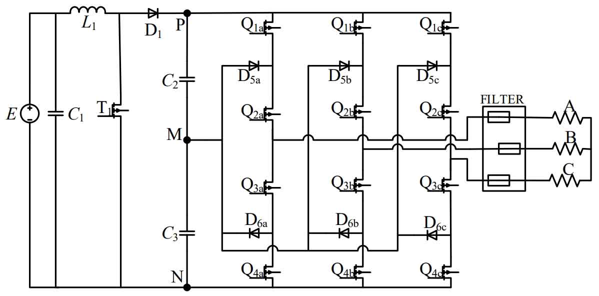
This article addresses the problem of excessive boost losses in the front stage of traditional boost type two-stage solar inverters, which limits their application scenarios. A novel three-level adjustable two-stage solar inverter is proposed, which can effectively reduce the switching frequency and amplitude of the subsequent stage solar inverter, without the need for large capacitors to maintain bus and midpoint voltage balance. This helps to improve conversion efficiency and reduce costs, making the two-stage inverter structure promising for application in high-voltage photovoltaic grid connected scenarios.
4. Main research content
This article proposes a new photovoltaic inverter topology and modulation strategy through in-depth research on multi-level inverter systems, and conducts simulation experiments and hardware circuit design on it. The main focus of this article can be divided into the following six parts:
(1) A brief analysis of the current energy situation is conducted to gain a deeper understanding of the current application status, prospects, and characteristics of photovoltaic power generation. Based on this, the basic structure of photovoltaic power generation systems is introduced, and the background and significance of this topic are explained.
(2) By introducing the background and advantages of multi-level solar inverters, this paper analyzes the working modes and characteristics of three typical multi-level solar inverters, and introduces their research status.
(3) Propose a three-level adjustable two-stage solar inverter suitable for photovoltaic power generation, introduce its circuit topology and working principle, analyze the advantages of solar inverters, and provide a design scheme for the main circuit soft switch. Fully consider the working relationship between the front and rear stages, adopt a joint control strategy of the front and rear circuit through theoretical analysis and mathematical modeling, and provide various LC parameters through calculation.
(4) Build a simulation system using MATLAB to verify the feasibility of the two-stage solar inverter and its modulation strategy proposed in this paper. Through simulation experiments, it is proven that the two-stage solar inverter and its modulation strategy proposed in this paper can effectively reduce the switching frequency of the solar inverter. Simultaneously establish a loss model for the two-stage inverter structure, calculate the conversion efficiency of each power point, and calculate the weighted efficiency.
(5) Design the hardware circuit of the two-stage inverter structure proposed in this article, mainly including the main control circuit, measurement circuit, and inverter circuit.