
In recent years, thin film solar panels have emerged as a promising alternative to traditional silicon-based photovoltaic technologies due to their low cost, flexibility, and potential for high efficiency. Among various thin film materials, copper zinc tin selenium (CZTSe) has gained significant attention for its optimal bandgap, high absorption coefficient, and earth-abundant constituents. However, the efficiency of CZTSe-based thin film solar panels still lags behind theoretical limits, primarily due to open-circuit voltage deficits and fill factor issues. Understanding the factors influencing device performance through simulation is crucial for advancing thin film solar panel technology. In this article, I explore the impact of key parameters on CZTSe thin film solar panel performance using numerical simulation, with a focus on series/parallel resistance, bulk defect states, and interface recombination.
Thin film solar panels typically consist of multiple layers, including a transparent conductive oxide, buffer layer, absorber layer, and back contact. For CZTSe devices, the structure often includes Al/ZnO:Al/i-ZnO/CdS/CZTSe/Mo on a glass substrate. The absorber layer, CZTSe, is the core component where photon absorption and carrier generation occur. Optimizing this layer and its interfaces is essential for enhancing the efficiency of thin film solar panels. Numerical simulation tools like SCAPS (Solar Cell Capacitance Simulator) allow for detailed analysis of device physics under various conditions, helping identify performance bottlenecks.
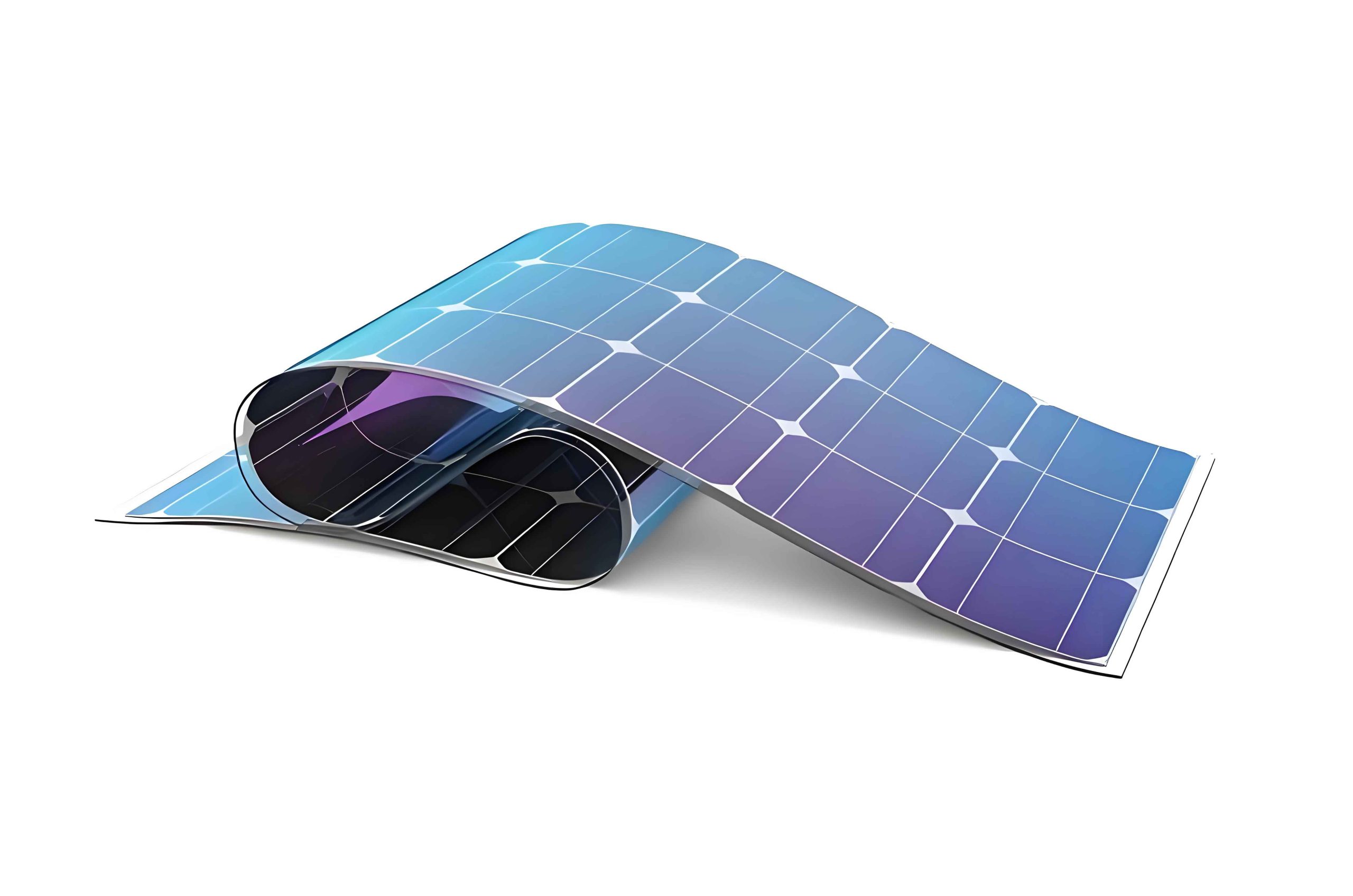
The performance of thin film solar panels is governed by several physical mechanisms, which can be described using fundamental equations. In SCAPS, the device behavior is simulated by solving Poisson’s equation and continuity equations for electrons and holes. Poisson’s equation relates the electrostatic potential to charge density:
$$ \nabla \cdot (\epsilon \nabla \phi) = -q (p – n + N_D – N_A), $$
where $\epsilon$ is the permittivity, $\phi$ is the electric potential, $q$ is the electron charge, $p$ and $n$ are hole and electron concentrations, and $N_D$ and $N_A$ are donor and acceptor concentrations, respectively. The continuity equations account for carrier transport and recombination:
$$ \nabla \cdot \mathbf{J}_n = q (R – G) + q \frac{\partial n}{\partial t}, $$
$$ -\nabla \cdot \mathbf{J}_p = q (R – G) + q \frac{\partial p}{\partial t}, $$
with $\mathbf{J}_n$ and $\mathbf{J}_p$ as electron and hole current densities, $R$ as recombination rate, and $G$ as generation rate. These equations form the basis for analyzing thin film solar panel performance under illumination and bias conditions.
To simulate a CZTSe thin film solar panel, I adopt material parameters from experimental data and literature. The absorber layer has a bandgap of approximately 1.01 eV, hole concentration of $1 \times 10^{16} \, \text{cm}^{-3}$, and hole mobility of $5 \, \text{cm}^2 \text{V}^{-1} \text{s}^{-1}$. Deep-level defects, such as those associated with V$_{\text{Sn}}$ or Cu$_{\text{Sn}}$, are introduced at 0.4 eV above the valence band maximum, acting as recombination centers. Interface states at the CdS/CZTSe junction are set at 0.5 eV above the valence band, with densities varied to study their impact. Other parameters, like electron affinity and dielectric constant, are based on standard values for thin film solar panel materials.
| Parameter | Value |
|---|---|
| Bandgap (eV) | 1.01 |
| Electron affinity (eV) | 4.5 |
| Dielectric constant | 8.0 |
| Conduction band effective density of states (cm$^{-3}$) | $2.2 \times 10^{18}$ |
| Valence band effective density of states (cm$^{-3}$) | $1.8 \times 10^{19}$ |
| Electron mobility (cm$^2$ V$^{-1}$ s$^{-1}$) | 100 |
| Hole mobility (cm$^2$ V$^{-1}$ s$^{-1}$) | 5 |
| Acceptor concentration (cm$^{-3}$) | $1 \times 10^{16}$ |
| Absorber thickness (μm) | 1.5 |
Series and parallel resistances are critical in determining the fill factor and efficiency of thin film solar panels. Series resistance ($R_s$) arises from contact resistance and bulk material resistance, while parallel resistance ($R_{sh}$) is related to shunt paths due to defects or grain boundaries. To analyze their effects, I vary $R_s$ from 0.01 to 2.5 Ω·cm$^2$ and $R_{sh}$ from 800 to 10$^4$ Ω·cm$^2$ in simulations. The results show that reducing $R_s$ significantly improves the fill factor, from 54% to 71%, leading to an efficiency increase from 7.55% to 9.98%. In contrast, increasing $R_{sh}$ has a minimal impact, with efficiency only rising to 7.61%. This indicates that series resistance is a major limiting factor for thin film solar panel performance, and optimizing contacts and material conductivity is essential.
Bulk defect states in the absorber layer influence carrier lifetime and recombination rates. In CZTSe thin film solar panels, deep-level defects can act as Shockley-Read-Hall (SRH) recombination centers, reducing open-circuit voltage and short-circuit current. The recombination rate via SRH mechanism is given by:
$$ R_{\text{SRH}} = \frac{n p – n_i^2}{\tau_p (n + n_1) + \tau_n (p + p_1)}, $$
where $n_i$ is the intrinsic carrier concentration, $\tau_n$ and $\tau_p$ are carrier lifetimes, and $n_1$, $p_1$ are parameters related to defect energy levels. I simulate the effect of bulk defect density ($N_t$) ranging from $1 \times 10^{10}$ to $1 \times 10^{15}$ cm$^{-3}$. The device parameters remain stable for $N_t$ below $3.162 \times 10^{12}$ cm$^{-3}$, corresponding to a minority carrier diffusion length of 1.3 μm, which is sufficient for carrier collection in a 1.5 μm thick absorber. Above this threshold, efficiency degrades rapidly due to increased recombination. This highlights the importance of controlling defect densities during the fabrication of thin film solar panels.
| Defect Density (cm$^{-3}$) | Open-Circuit Voltage (V) | Short-Circuit Current (mA/cm$^2$) | Fill Factor (%) | Efficiency (%) |
|---|---|---|---|---|
| $1 \times 10^{10}$ | 0.383 | 32.5 | 71.2 | 8.85 |
| $1 \times 10^{12}$ | 0.382 | 32.3 | 70.8 | 8.76 |
| $3.162 \times 10^{12}$ | 0.380 | 31.9 | 70.1 | 8.52 |
| $1 \times 10^{13}$ | 0.375 | 30.5 | 68.3 | 7.82 |
| $1 \times 10^{14}$ | 0.360 | 27.8 | 64.2 | 6.42 |
| $1 \times 10^{15}$ | 0.335 | 24.1 | 58.9 | 4.75 |
Interface recombination at the buffer/absorber junction is another key factor affecting thin film solar panel performance. The conduction band offset ($\Delta E_c$) between CdS and CZTSe determines the interface behavior. A “spike-like” structure with $\Delta E_c > 0$ (e.g., 0.3 eV) is beneficial, as it reduces recombination while allowing carrier transport. In contrast, a “cliff-like” structure with $\Delta E_c < 0$ enhances recombination due to lower activation energy. I simulate interface defect density ($D_{it}$) from $10^{10}$ to $10^{15}$ cm$^{-2}$ for both cases. For spike-like structures, $D_{it}$ has negligible impact on open-circuit voltage, which decreases only from 0.383 V to 0.378 V. However, for cliff-like structures with $\Delta E_c = -0.1$ eV, the voltage drops sharply to 0.231 V at high $D_{it}$, causing efficiency to fall from 7.13% to 3.0%. Thus, optimizing interface properties is critical for high-efficiency thin film solar panels.
The efficiency of thin film solar panels can be predicted by combining all influencing factors. Using optimized parameters—$R_s = 0.01$ Ω·cm$^2$, $R_{sh} = 10^4$ Ω·cm$^2$, $N_t = 1 \times 10^{12}$ cm$^{-3}$, and $D_{it} = 1 \times 10^{10}$ cm$^{-2}$—the simulated efficiency reaches 11.3%, with a fill factor of 74.5% and short-circuit current of 33.2 mA/cm$^2$. Further improvement by eliminating band-tail states (which cause bandgap narrowing) can boost open-circuit voltage, leading to an efficiency of 14.8%. This demonstrates the potential of CZTSe-based thin film solar panels if material and interface quality are enhanced.
To achieve these gains, fabrication processes for thin film solar panels must focus on reducing series resistance through better contacts and higher conductivity layers. Bulk defect control requires precise stoichiometry and annealing conditions to minimize deep-level states. Interface engineering involves selecting buffer materials with favorable band alignment, such as ZnS or In$_2$S$_3$, which can form spike-like structures with CZTSe. Additionally, advanced characterization techniques like photoluminescence and capacitance-voltage measurements can help monitor defect densities in thin film solar panels.
Beyond CZTSe, other thin film solar panel technologies, such as CdTe and CIGS, also benefit from similar simulation approaches. For instance, CdTe thin film solar panels often face challenges with back-contact recombination, while CIGS devices require careful control of Ga grading for optimal bandgap profiling. SCAPS simulations can model these effects by adjusting parameters like doping profiles and defect distributions. The general principles discussed here—managing resistances, defects, and interfaces—apply broadly to thin film solar panel optimization.
Future directions for thin film solar panel research include the development of tandem structures, where multiple absorber layers with different bandgaps are stacked to capture a broader solar spectrum. Simulation tools can guide the design of such devices by predicting current matching and optical losses. Moreover, emerging materials like perovskites can be integrated with CZTSe in hybrid thin film solar panels, offering pathways to efficiencies above 20%. However, stability and scalability remain challenges that require ongoing simulation and experimental efforts.
In conclusion, thin film solar panels represent a versatile and cost-effective photovoltaic technology. Through numerical simulation, I have analyzed the impact of series/parallel resistance, bulk defects, and interface recombination on CZTSe device performance. Key findings indicate that series resistance reduction and defect control are paramount for efficiency improvements. By optimizing these factors, thin film solar panels can achieve efficiencies competitive with conventional silicon cells, supporting the transition to sustainable energy. Continuous advancement in simulation methodologies and material science will further propel thin film solar panel technology toward its full potential.
The equations and tables presented here provide a foundation for understanding thin film solar panel physics. For instance, the diode equation for a solar cell under illumination is:
$$ J = J_0 \left( \exp\left(\frac{qV}{nkT}\right) – 1 \right) – J_{\text{ph}}, $$
where $J_0$ is the reverse saturation current, $n$ is the ideality factor, $k$ is Boltzmann’s constant, $T$ is temperature, and $J_{\text{ph}}$ is the photocurrent. This equation, combined with resistance and recombination models, allows comprehensive analysis of thin film solar panel performance under various conditions.
In summary, thin film solar panels offer significant advantages in terms of material usage and application flexibility. The insights from simulation studies, as discussed, guide practical fabrication strategies to overcome efficiency barriers. As research progresses, thin film solar panels are poised to play a crucial role in the global renewable energy landscape.