
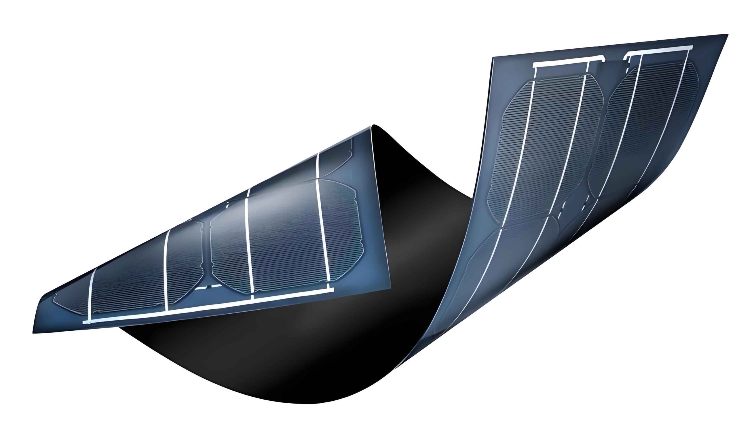
The relentless consumption of fossil fuels and the escalating environmental crisis have placed sustainable energy solutions at the forefront of global scientific and engineering efforts. Among the various renewable energy technologies, photovoltaics—the direct conversion of sunlight into electricity—stands out as a pivotal and promising path forward. While silicon-based solar cells dominate the current market, their production is often energy-intensive and costly. This has driven significant research into alternative photovoltaic materials, particularly thin film solar panels. These panels utilize layers of light-absorbing semiconductor materials that are only a few micrometers thick, deposited onto low-cost substrates like glass, plastic, or metal. This approach offers the potential for lower material usage, reduced manufacturing costs, and the ability to create flexible, lightweight modules.
The foundational breakthrough for modern thin film solar panels using nanostructured materials came with the development of the dye-sensitized solar cell (DSSC). In 1991, O’Regan and Grätzel demonstrated a cell based on nanoporous titanium dioxide (TiO₂) sensitized with a ruthenium dye, achieving a remarkable photon-to-electron conversion efficiency and introducing the concept of a mesoscopic, high-surface-area architecture. This work ignited widespread interest in using nanostructured wide-bandgap metal oxides, such as TiO₂, zinc oxide (ZnO), and tin oxide (SnO₂), as the electron-transporting scaffold in photoelectrochemical and solid-state solar cells. However, a fundamental limitation of these oxides is their large bandgap energy (typically >3.0 eV), which restricts light absorption primarily to the ultraviolet region, constituting only a small fraction of the solar spectrum.
To overcome this limitation and harness visible light—the most abundant part of solar radiation—several strategies have been developed. These include doping with transition metals to create intra-bandgap states and, more effectively, sensitization with narrow-bandgap semiconductors. Coupling a wide-bandgap oxide with a smaller-bandgap sensitizer creates a type-II heterojunction, which facilitates the spatial separation of photogenerated electron-hole pairs, thereby enhancing charge collection and overall device performance. Historically, II-VI group compounds like cadmium sulfide (CdS) and lead sulfide (PbS) have been extensively studied due to their suitable bandgaps and excellent optoelectronic properties. Nevertheless, the inherent toxicity of cadmium and lead raises serious environmental and health concerns, hindering their large-scale deployment. Consequently, the search for non-toxic, earth-abundant alternative sensitizers is crucial for the sustainable development of next-generation thin film solar panels.
Indium sulfide (In₂S₃), a III-VI group semiconductor, has emerged as a highly promising candidate for this role. It possesses several advantageous properties: moderate bandgap energy (approximately 2.0-2.3 eV, enabling visible light absorption), excellent chemical stability, high photoconductivity, and low toxicity. These characteristics make In₂S₃ an ideal sensitizer for creating environmentally benign and efficient heterojunction thin film solar panels. In this article, I will delve into the core principles of such devices, discuss common fabrication techniques, and present a detailed case study on the synthesis and characterization of an In₂S₃/ZnO heterostructure nanosheet array, highlighting its superior photoelectrochemical properties as a model system for advanced thin film solar panel technology.
Fundamental Working Principles
The operation of a semiconductor-sensitized solar cell, a key variant of thin film solar panels, hinges on the photovoltaic effect at a heterojunction interface. When a photon with energy greater than the bandgap of the sensitizer (e.g., In₂S₃) is absorbed, it excites an electron from the valence band (VB) to the conduction band (CB), creating an electron-hole pair. The relative alignment of the energy bands of the two semiconductors is critical. For efficient charge separation, a type-II (“staggered”) band alignment is desired.
In an ideal In₂S₃/ZnO heterojunction, the conduction band minimum (CBM) of ZnO is situated at a lower energy level than that of In₂S₃, while the valence band maximum (VBM) of In₂S₃ is higher than that of ZnO. This energy level offset creates driving forces for charge transfer: photogenerated electrons in the CB of In₂S₃ can inject efficiently into the CB of ZnO, while photogenerated holes remain in the VB of In₂S₃ or are transferred to a hole-transport medium/electrolyte. This spatial separation prevents rapid recombination of electrons and holes. The injected electrons then percolate through the interconnected network of the ZnO nanostructure (e.g., nanosheet array) to the transparent conductive oxide (TCO) substrate and through the external circuit, performing work. The holes are subsequently scavenged by a redox couple in the electrolyte (e.g., S²⁻/Sₓ²⁻ in a polysulfide electrolyte) in a photoelectrochemical cell configuration, completing the circuit.
The overall power conversion efficiency (η) of such a cell is determined by several key parameters:
$$ \eta = \frac{J_{sc} \times V_{oc} \times FF}{P_{in}} $$
where \(J_{sc}\) is the short-circuit current density, \(V_{oc}\) is the open-circuit voltage, \(FF\) is the fill factor, and \(P_{in}\) is the incident solar power density. Enhancing \(J_{sc}\) involves improving light harvesting (through extended absorption range and increased surface area) and maximizing the charge injection/collection efficiency. The \(V_{oc}\) is largely governed by the quasi-Fermi level splitting, which is related to the difference between the electron quasi-Fermi level in the oxide and the redox potential of the electrolyte.
Material Systems for Thin Film Solar Panels
Beyond the model In₂S₃/ZnO system, the landscape of materials for thin film solar panels is diverse. The table below summarizes some of the prominent absorber/sensitizer materials, their typical partners, and key characteristics.
| Absorber/Sensitizer Type | Example Materials | Typical Partner (Scaffold) | Bandgap (eV) | Advantages | Challenges |
|---|---|---|---|---|---|
| Chalcogenides | CdTe, CIGS (Cu(In,Ga)(Se,S)₂) | CdS, ZnO | ~1.0-1.5 | High efficiency (>22%), mature technology | Te, In scarcity; Cd toxicity (for CdTe/CdS) |
| II-VI Quantum Dots | CdSe, PbS QDs | TiO₂, ZnO | Tunable (1.0-2.5) | Size-tunable bandgap, multiple exciton generation potential | Toxicity, organic ligand management, stability |
| Perovskites | CH₃NH₃PbI₃, CsPbI₃ | TiO₂, SnO₂, Al₂O₃ | ~1.5-2.3 | Rapid efficiency rise (>25%), excellent absorption, low-cost processing | Lead toxicity, moisture/thermal instability |
| Kesterites | CZTS (Cu₂ZnSnS₄) | CdS, ZnS | ~1.4-1.5 | Earth-abundant, non-toxic constituents | Complex phase control, efficiency lagging (~12%) |
| III-VI Sensitizers | In₂S₃, Sb₂S₃ | TiO₂, ZnO | ~1.7-2.3 | Lower toxicity, good stability, suitable bandgap | Optimization of interface and deposition control |
As seen in the table, III-VI sensitizers like In₂S₃ offer a compelling compromise between performance, stability, and environmental impact, making them a focal point for research into sustainable thin film solar panels.
Fabrication Techniques for Nanostructured Thin Films
The performance of thin film solar panels is intimately linked to the morphology and quality of the constituent layers. Nanostructuring the wide-bandgap oxide scaffold is crucial as it provides a vast interfacial area for sensitizer attachment and light absorption. Various chemical and physical methods are employed.
1. Chemical Solution Methods: These are cost-effective and scalable for oxide growth.
• Hydrothermal/Solvothermal Synthesis: This involves a chemical reaction in an aqueous or non-aqueous solution within a sealed autoclave at elevated temperature and pressure. It allows for the direct growth of well-defined nanostructures (e.g., nanorods, nanosheets, nanoflowers) on substrates. The morphology can be controlled by precursors, concentration, pH, temperature, and time.
• Successive Ionic Layer Adsorption and Reaction (SILAR): A cyclic, solution-based technique ideal for depositing thin, conformal layers of sensitizers like In₂S₃. The substrate is sequentially immersed in cationic and anionic precursor solutions, with rinsing steps in between. Each cycle deposits a monolayer or sub-monolayer, allowing precise thickness control by varying the number of cycles. The reaction for In₂S₃ can be represented as:
$$ 2\,In^{3+}_{(aq)} + 3\,S^{2-}_{(aq)} \rightarrow In_2S_{3(s)} $$
• Chemical Bath Deposition (CBD): Similar to SILAR but involves immersion in a single bath containing all precursors for a prolonged period, leading to film growth via heterogeneous nucleation on the substrate.
2. Physical Vapor Deposition (PVD) Methods: These offer high purity and good film control.
• Sputtering: Energetic ions bombard a target material, ejecting atoms that condense on the substrate to form a film. Excellent for depositing uniform oxide and absorber layers over large areas.
• Thermal Evaporation: The source material is heated in a vacuum until it evaporates, condensing on the cooler substrate. Commonly used for depositing metals and some compound semiconductors.
Characterization of Thin Film Solar Panel Materials
Comprehensive characterization is essential to correlate the structural, morphological, and optical properties of the fabricated films with their photovoltaic performance.
Structural Analysis: X-ray diffraction (XRD) is used to determine the crystalline phase, crystallite size, and preferred orientation of both the scaffold and the sensitizer.
Morphological Analysis: Scanning electron microscopy (SEM) and transmission electron microscopy (TEM) provide direct visualization of the nanostructure’s size, shape, density, and coverage, as well as the heterojunction interface.
Optical Analysis: UV-Visible absorption spectroscopy measures the light-harvesting capability and estimates the bandgap energy (\(E_g\)) using the Tauc plot method. For a direct bandgap semiconductor:
$$ (\alpha h\nu)^2 = A(h\nu – E_g) $$
where \(\alpha\) is the absorption coefficient, \(h\nu\) is the photon energy, and \(A\) is a constant.
Photoelectrochemical (PEC) Characterization: This evaluates the actual performance of the film as a photoelectrode. Key measurements include:
• Linear Sweep Voltammetry (J-V curves): Measures the photocurrent density (\(J_{ph}\)) as a function of applied bias under simulated sunlight (AM 1.5G).
• Chronoamperometry (I-t curves): Records the transient photocurrent response under on/off illumination cycles at a constant bias, indicating charge separation kinetics and stability.
• Electrochemical Impedance Spectroscopy (EIS): Models the charge transport and recombination processes within the cell. The Nyquist plot often shows semicircles corresponding to charge transfer resistance at the electrode/electrolyte interface (\(R_{ct}\)). A lower \(R_{ct}\) signifies more efficient charge injection and separation.
Case Study: In₂S₃/ZnO Nanosheet Array Heterojunction
To illustrate the principles and process, I will now detail the fabrication and analysis of a specific heterostructure relevant to thin film solar panels. The goal is to create a vertically aligned ZnO nanosheet array sensitized with In₂S₃ nanoparticles.
Step 1: Synthesis of ZnO Nanosheet Array. A two-step chemical method is employed. First, a thin seed layer of ZnO nanoparticles is deposited on a cleaned fluorine-doped tin oxide (FTO) glass substrate using multiple SILAR cycles with zinc acetate, followed by annealing. This seed layer promotes oriented growth. Subsequently, the seeded substrate is placed in a hydrothermal reactor containing an aqueous solution of zinc acetate, sodium hydroxide, and a capping agent (sodium citrate). The reaction proceeds at 95°C for 12 hours. The citrate ions selectively adsorb onto certain crystal faces, promoting two-dimensional growth, resulting in a uniform array of vertically standing ZnO nanosheets with high surface area.
Step 2: Deposition of In₂S₃ Sensitizer. The as-grown ZnO nanosheet array is then sensitized using the SILAR technique. The substrate is cyclically immersed in separate cationic (0.00625 M InCl₃) and anionic (0.009375 M Na₂S) precursor solutions, with deionized water rinses in between. Each immersion lasts 30 seconds. The number of SILAR cycles (N) is varied (e.g., 3, 5, 7, 9) to control the In₂S₃ loading and film thickness. The sample is finally annealed at 300°C in an inert atmosphere to improve crystallinity and interfacial contact.
Structural and Morphological Analysis. XRD patterns confirm the presence of hexagonal wurtzite ZnO and cubic β-In₂S₃ phases. SEM images reveal the transformation: pristine ZnO nanosheets are distinct and separated, offering a porous network. After In₂S₃ deposition, the nanosheets become thicker and the gaps are partially filled, yet a highly porous morphology is retained, which is vital for electrolyte penetration in PEC cells.
Optical Properties. The UV-Vis absorption spectra show a dramatic change. The pure ZnO array absorbs only below ~370 nm (UV region). After In₂S₃ sensitization, a strong absorption tail extends into the visible region up to ~550 nm, confirming successful bandgap engineering and enhanced light harvesting for the thin film solar panel heterostructure.
Photoelectrochemical Performance. The PEC properties are evaluated in a three-electrode cell with a polysulfide electrolyte. The results are striking:
• The J-V curves show that the photocurrent density is highly dependent on the number of SILAR cycles (N). An optimal value (e.g., N=7) yields a maximum photocurrent density approximately four times higher than that of the bare ZnO nanosheet array.
• The I-t curves show fast, stable, and reproducible photoresponses for all heterostructure electrodes, with the highest photocurrent again corresponding to the optimal N=7 sample.
• The enhancement can be attributed to two main factors: 1) Extended visible light absorption by In₂S₃, generating more charge carriers. 2) Efficient charge separation at the type-II In₂S₃/ZnO heterojunction, which reduces recombination.
• EIS Nyquist plots provide further evidence. The diameter of the semicircular arc (representing \(R_{ct}\)) for the optimal In₂S₃/ZnO electrode is significantly smaller than that for bare ZnO. This lower charge transfer resistance corroborates more efficient electron injection from In₂S₃ into ZnO and subsequently to the external circuit.
The decrease in performance for N>7 (e.g., N=9) is attributed to excessive In₂S₃ thickness, which may increase the series resistance, hinder electrolyte diffusion to the ZnO interface, and promote bulk recombination within the In₂S₃ layer itself before electrons can be injected into ZnO. This underscores the importance of optimizing sensitizer deposition parameters in the design of efficient thin film solar panels.
Conclusion and Future Perspectives
The development of nanostructured heterojunctions, as exemplified by the In₂S₃/ZnO system, represents a critical pathway toward high-performance, cost-effective, and environmentally sustainable thin film solar panels. By combining the high electron mobility and tunable morphology of wide-bandgap oxides like ZnO with the strong visible-light absorption of non-toxic sensitizers like In₂S₃, significant improvements in photocurrent generation can be achieved through effective charge separation.
Future research in this field will focus on several key challenges and opportunities:
1. Interface Engineering: Further reducing recombination at the heterojunction interface by introducing ultrathin passivation layers (e.g., Al₂O₃, TiO₂ via atomic layer deposition) or developing novel buffer layers.
2. Morphology Control: Designing more sophisticated hierarchical nanostructures (e.g., branched nanorods, porous nanosheets) to maximize light scattering and surface area while maintaining efficient charge transport pathways.
3. Alternative Sensitizers: Exploring other benign, abundant materials like Sb₂(S,Se)₃, Bi₂S₃, or novel perovskite quantum dots as sensitizers for oxide scaffolds.
4. Solid-State Devices: Transitioning from liquid-electrolyte-based PEC cells to solid-state heterojunction solar cells using organic hole-transport materials (e.g., spiro-OMeTAD) or inorganic p-type semiconductors, which is essential for improving long-term stability and enabling flexible thin film solar panel applications.
5. Scalable Fabrication: Adapting laboratory-scale synthesis techniques like SILAR and hydrothermal methods to roll-to-roll or other high-throughput manufacturing processes suitable for commercial production of thin film solar panels.
In conclusion, the continuous innovation in materials synthesis, heterostructure design, and device architecture holds immense promise for advancing thin film solar panel technology, bringing us closer to a future powered by abundant, clean, and low-cost solar energy.