
As a researcher in the field of photovoltaics, I have witnessed the rapid evolution of solar energy technologies. Among these, thin film solar panels stand out as a promising solution for large-scale, cost-effective renewable energy generation. In this article, I will delve into the principles, advancements, and future prospects of thin film solar panels, with a focus on copper-zinc-tin-sulfur-selenium (CZTSSe) based cells. Thin film solar panels offer numerous advantages, including low material usage, flexibility, and suitability for diverse applications, making them a key player in the global shift toward clean energy. Throughout this discussion, I will emphasize the importance of thin film solar panels in addressing energy crises and environmental challenges.
The fundamental principle behind thin film solar panels is the photovoltaic effect, where light absorption in a semiconductor material generates electron-hole pairs. These carriers are separated by an internal electric field, typically formed at a p-n junction, and collected at electrodes to produce electricity. The efficiency of a thin film solar panel depends on factors such as the absorber material’s bandgap, absorption coefficient, and defect density. For an ideal solar cell, the maximum theoretical efficiency, known as the Shockley-Queisser limit, is around 32% for a single-junction device under standard sunlight. This limit can be expressed as:
$$\eta_{\text{max}} = \frac{P_{\text{max}}}{P_{\text{in}}} = \frac{J_{sc} \times V_{oc} \times FF}{P_{\text{in}}}$$
where $\eta_{\text{max}}$ is the maximum efficiency, $J_{sc}$ is the short-circuit current density, $V_{oc}$ is the open-circuit voltage, $FF$ is the fill factor, and $P_{\text{in}}$ is the incident solar power. Thin film solar panels often use direct-bandgap semiconductors with high absorption coefficients ($\alpha > 10^4 \text{ cm}^{-1}$), allowing for thinner absorber layers (e.g., 1-2 μm) compared to crystalline silicon cells (~200 μm). This reduces material costs and enables lightweight, flexible designs, expanding the applications of thin film solar panels.
CZTSSe is a quaternary semiconductor material that has gained attention as an absorber for thin film solar panels due to its tunable bandgap (1.0–1.5 eV), high absorption coefficient, and earth-abundant, low-cost elements. The crystal structure of CZTSSe is derived from zinc blende, with a kesterite-type arrangement (space group $I\bar{4}$) where Cu, Zn, Sn, and S/Se atoms form tetrahedral coordination. The bandgap $E_g$ can be adjusted by varying the S/Se ratio, following Vegard’s law approximately as:
$$E_g(x) = (1-x)E_g(\text{CZTSe}) + xE_g(\text{CZTS})$$
where $x$ is the sulfur fraction. However, CZTSSe has a narrow phase stability region, leading to challenges in synthesizing pure phases without secondary compounds like ZnS or Cu$_2$SnS$_3$, which can degrade the performance of thin film solar panels. The table below summarizes key properties of CZTSSe compared to other thin film solar panel materials.
| Material | Bandgap (eV) | Absorption Coefficient (cm-1) | Record Efficiency (%) | Advantages | Challenges |
|---|---|---|---|---|---|
| CZTSSe | 1.0–1.5 | >104 | 13.0 | Abundant elements, low cost | Defect complexes, phase purity |
| CIGS | 1.0–1.7 | >105 | 23.4 | High efficiency, mature technology | Rare elements (In, Ga) |
| CdTe | 1.5 | >105 | 22.1 | Low-cost production | Toxicity of Cd, Te scarcity |
| Perovskite | 1.5–2.3 | >104 | 25.7 | Rapid efficiency growth | Stability issues |
The development of CZTSSe-based thin film solar panels has progressed through various fabrication techniques. Common methods include vacuum-based processes like sputtering and evaporation, as well as solution-based approaches such as nanocrystal ink deposition and sol-gel synthesis. Solution processing is particularly attractive for thin film solar panels due to its low energy consumption and scalability. In my research, I have explored precursor solutions involving environmentally friendly solvents like water-based systems. For example, the formation of CZTSSe films can be described by reaction kinetics:
$$\text{Cu}^{2+} + \text{Zn}^{2+} + \text{Sn}^{4+} + 4\text{S}^{2-} \rightarrow \text{Cu}_2\text{ZnSnS}_4$$
During selenization, Se vapor replaces S, adjusting the bandgap. The growth of large grains is crucial for reducing grain boundary recombination in thin film solar panels. Alkali metal doping (e.g., Na, Li) has been shown to enhance grain growth and electrical properties, as alkali ions segregate at grain boundaries and passify defects. The efficiency $\eta$ of a thin film solar panel can be modeled as:
$$\eta = \frac{J_{sc} V_{oc} FF}{P_{\text{in}}} \times 100\%$$
where $J_{sc}$ is influenced by absorption and carrier collection, $V_{oc}$ by recombination losses, and $FF$ by series and shunt resistances. For CZTSSe cells, the open-circuit voltage deficit ($\Delta V_{oc} = E_g/q – V_{oc}$) is often high (>0.5 V), limiting efficiency. This deficit arises from bulk and interface recombination, which I will discuss later.
To understand the performance of thin film solar panels, it is essential to analyze the current-voltage characteristics. The diode equation for a solar cell under illumination is:
$$J = J_0 \left[ \exp\left(\frac{q(V + J R_s)}{A k T}\right) – 1 \right] + \frac{V + J R_s}{R_{sh}} – J_L$$
where $J_0$ is the reverse saturation current density, $R_s$ is series resistance, $R_{sh}$ is shunt resistance, $A$ is the ideality factor, $k$ is Boltzmann’s constant, $T$ is temperature, and $J_L$ is the light-generated current density. For thin film solar panels, minimizing $J_0$ is key to improving $V_{oc}$, as $V_{oc} \approx \frac{A k T}{q} \ln(J_L/J_0)$. In CZTSSe, $J_0$ is elevated due to defect-assisted recombination, such as through Cu$_{\text{Zn}}$ anti-site defects or Sn$_{\text{Zn}}$ deep levels. These defects can be quantified using admittance spectroscopy or deep-level transient spectroscopy, common tools in thin film solar panel research.
The structure of a typical CZTSSe thin film solar panel consists of a Mo back contact, CZTSSe absorber layer (1–2 μm), CdS buffer layer (50–100 nm), intrinsic ZnO layer (50–100 nm), and transparent conducting oxide (e.g., ITO) front electrode. This design optimizes light absorption and carrier collection. The band alignment at the CZTSSe/CdS interface is critical; a “cliff-like” conduction band offset ($\Delta E_c < 0$) can enhance interface recombination, while a “spike-like” offset ($\Delta E_c > 0$) is preferable. The band offset $\Delta E_c$ can be estimated from electron affinity differences:
$$\Delta E_c = \chi_{\text{CdS}} – \chi_{\text{CZTSSe}}$$
where $\chi$ is the electron affinity. For CZTSSe with high S content, $\Delta E_c$ tends to be negative, degrading $V_{oc}$. Thus, interface engineering is vital for high-performance thin film solar panels. Alternative buffer layers like Zn(O,S) or In-doped CdS have been explored to improve band alignment.
Bulk defects in CZTSSe, such as vacancy clusters or cation disorder, also limit the efficiency of thin film solar panels. First-principles calculations show that low-formation-energy defects like V$_{\text{Cu}}$ (acceptors) and Cu$_{\text{Zn}}$ (donors) can cause charge compensation and band tailing. The net carrier concentration $p$ in p-type CZTSSe is given by:
$$p = N_A – N_D$$
where $N_A$ and $N_D$ are acceptor and donor densities, respectively. Non-stoichiometric compositions (e.g., Cu-poor and Zn-rich) are often used to maximize $p$ and minimize recombination. Doping with elements like Ge or Cd can suppress harmful defects. For instance, Cd substitution on Zn sites reduces Sn$_{\text{Zn}}$ formation, as shown by:
$$\text{Cd}_{\text{Zn}} + \text{Sn}_{\text{Zn}} \rightarrow \text{Cd}_{\text{Zn}} + \text{Sn}_{\text{bulk}}$$
This improves carrier lifetime $\tau$, which affects $J_{sc}$ and $V_{oc}$ through the diffusion length $L_D = \sqrt{D\tau}$, where $D$ is the diffusion coefficient. Enhancing $\tau$ is a ongoing goal for thin film solar panels.
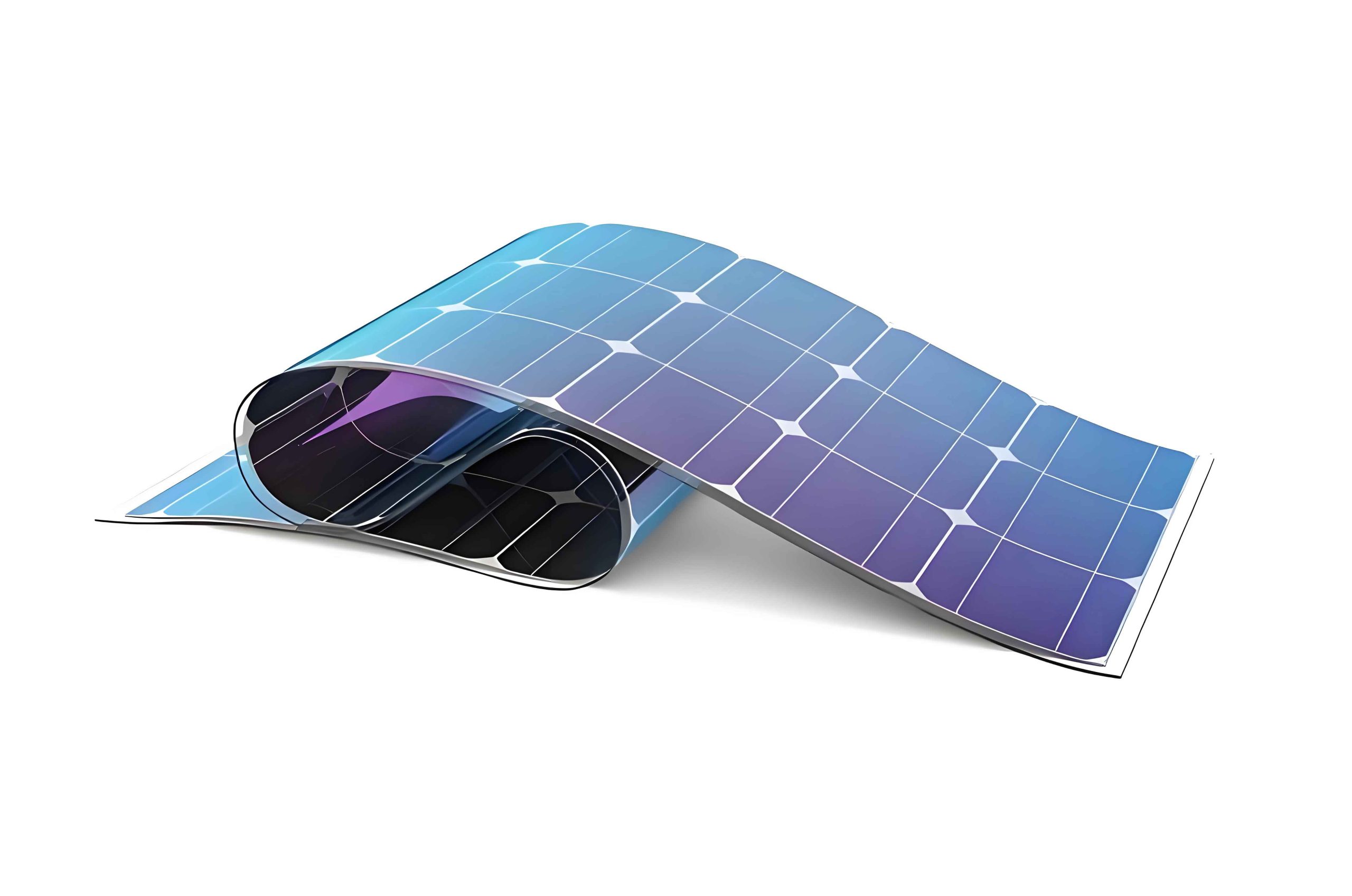
The evolution of CZTSSe thin film solar panel efficiency over time highlights the research progress. From initial reports of ~5% efficiency in the early 2000s, the record has climbed to 13% recently, driven by improvements in absorber quality and interface control. However, this still lags behind CIGS thin film solar panels (>22%), indicating room for growth. The table below charts efficiency milestones for CZTSSe thin film solar panels, emphasizing the impact of fabrication techniques.
| Year | Efficiency (%) | Fabrication Method | Key Innovation |
|---|---|---|---|
| 2005 | 5.7 | Sputtering | Basic device structure |
| 2010 | 9.7 | Hydrazine solution | Liquid-phase processing |
| 2014 | 12.6 | Nanocrystal ink | Grain growth control |
| 2020 | 12.8 | Water-based solution | Eco-friendly precursors |
| 2022 | 13.0 | DMSO solution | Valence state control |
Looking forward, the prospects for CZTSSe thin film solar panels are bright. To push efficiency beyond 15%, strategies include defect passivation, bandgap grading, and tandem designs. Tandem thin film solar panels, which stack multiple absorber layers, can surpass the single-junction limit. The efficiency of a tandem cell is approximated by:
$$\eta_{\text{tandem}} = \eta_{\text{top}} + \eta_{\text{bottom}} – \eta_{\text{top}}\eta_{\text{bottom}}$$
where $\eta_{\text{top}}$ and $\eta_{\text{bottom}}$ are the efficiencies of the top and bottom cells, respectively. CZTSSe, with its tunable bandgap, could serve as a bottom cell in perovskite/CZTSSe tandems, potentially achieving >30% efficiency. Moreover, the flexibility and lightweight nature of thin film solar panels enable applications in building-integrated photovoltaics (BIPV), portable electronics, and space missions, where traditional silicon panels are less feasible.
In conclusion, thin film solar panels, particularly those based on CZTSSe, represent a critical technology for sustainable energy. As a researcher, I believe that overcoming challenges in material synthesis and interface engineering will unlock higher efficiencies and broader adoption. Thin film solar panels offer a low-cost, environmentally friendly path to harnessing solar energy, contributing to global carbon neutrality goals. Through continued innovation in fabrication processes and device physics, thin film solar panels will play a pivotal role in the renewable energy landscape, making solar power accessible and affordable worldwide. The journey of thin film solar panels from lab to market is underway, and I am optimistic about their future impact.
To further illustrate the technical aspects, let’s consider the detailed balance limit for thin film solar panels. The maximum $J_{sc}$ can be calculated by integrating the solar spectrum:
$$J_{sc} = q \int_{E_g}^{\infty} \phi(E) \, dE$$
where $\phi(E)$ is the photon flux at energy $E$. For AM1.5G spectrum, this yields $J_{sc} \approx 40 \text{ mA/cm}^2$ for a 1.5 eV bandgap. The $V_{oc}$ limit is given by:
$$V_{oc}^{\text{max}} = \frac{E_g}{q} – \frac{kT}{q} \ln\left(\frac{J_{00}}{J_{sc}}\right)$$
where $J_{00}$ is a material-dependent prefactor. In practice, thin film solar panels suffer from non-radiative recombination, reducing $V_{oc}$. The external radiative efficiency (ERE) quantifies this:
$$\text{ERE} = \frac{J_{rad}}{J_{total}}$$
where $J_{rad}$ is the radiative current. Improving ERE through defect control is essential for thin film solar panels.
Another key area is the stability of thin film solar panels. Accelerated aging tests under light, heat, and humidity help predict lifetime. The degradation rate can be modeled with Arrhenius equation:
$$k = A \exp\left(-\frac{E_a}{kT}\right)$$
where $k$ is the rate constant, $A$ is the pre-exponential factor, and $E_a$ is activation energy. Encapsulation and stable materials are crucial for commercial thin film solar panels.
In summary, thin film solar panels are a versatile and promising technology. With ongoing research into materials like CZTSSe, efficiencies will rise, costs will fall, and applications will expand. I encourage continued investment in thin film solar panel R&D to accelerate the energy transition. The potential of thin film solar panels to provide clean, affordable power is immense, and as we refine these devices, they will become a cornerstone of global energy systems.