
The pursuit of sustainable and cost-effective energy conversion technologies has positioned thin film solar panels as a critical area of research and development. Among the various materials explored, Cu2ZnSn(S,Se)4 (CZTSSe) has garnered significant attention for thin film solar panel applications. This kesterite-type semiconductor offers several compelling advantages: a high absorption coefficient exceeding 104 cm-1, a tunable direct bandgap between 1.0 and 1.5 eV, and the abundance and non-toxicity of its constituent elements. These properties make it a promising candidate for next-generation, low-cost thin film solar panels. The core of such a device is the absorber layer, whose quality—encompassing phase purity, crystallinity, grain morphology, and interface properties—directly dictates the final photovoltaic performance. Consequently, optimizing the fabrication process of the CZTSSe absorber is paramount.
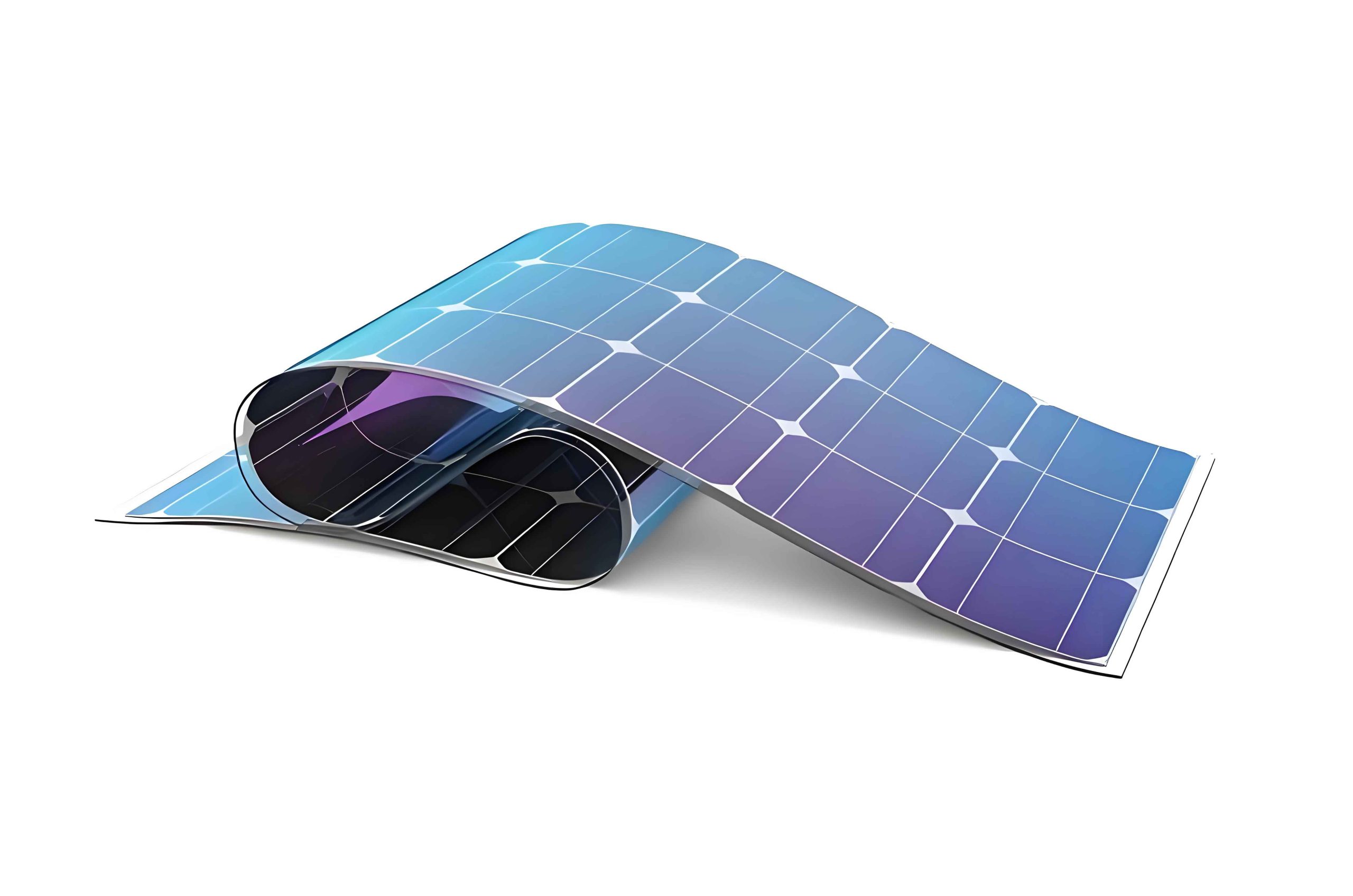
Fabrication methods for CZTSSe thin films are broadly categorized into vacuum-based and non-vacuum techniques. While vacuum methods like sputtering offer high purity, they involve complex and costly equipment. Solution-based non-vacuum methods, particularly those using precursor solutions, present a scalable and economical pathway for manufacturing thin film solar panels. A common solution-process involves depositing a metal-chalcogenide precursor film (often labeled CZTS) followed by a critical high-temperature annealing step in a selenium (Se) vapor atmosphere, known as selenization. This selenization process is where the amorphous or nanocrystalline precursor transforms into the desired, large-grained CZTSSe absorber. The selenization parameters—including the thermal profile (ramp rates, steps), peak temperature, dwell time, and Se partial pressure—profoundly influence the reaction pathways, grain growth kinetics, and final microstructure of the thin film solar panel absorber. This article delves into a systematic investigation of these selenization parameters to elucidate their impact on absorber quality and device performance.
Fabrication and Selenization of CZTSSe Absorbers
The fabrication of the CZTSSe thin film solar panel absorber begins with the preparation of a precursor solution. Typically, copper, zinc, and tin salts (e.g., acetates or chlorides) along with a sulfur source like thiourea are dissolved in a coordinating solvent such as dimethyl sulfoxide (DMSO). This yields a clear, homogeneous precursor ink. The ink is then deposited onto a molybdenum (Mo)-coated glass substrate via spin-coating. Multiple coating and low-temperature pyrolysis cycles are performed to build up the desired thickness (usually >1 µm) of the CZTS precursor film.
The selenization process is the transformative step. The precursor-coated substrate is placed in a sealed graphite box or a tubular furnace along with elemental Se pellets. The atmosphere is controlled, typically using inert nitrogen (N2) gas. The thermal treatment converts the CZTS film into CZTSSe by incorporating Se and promoting crystal growth. The key variables studied here are:
- Selenization Profile (One-Step vs. Two-Step): In a one-step profile, the temperature is ramped directly to a high selenization temperature (e.g., 560°C). In a two-step profile, the sample is first held at an intermediate temperature (e.g., 350°C) to allow Se infiltration and the formation of intermediate phases, before ramping to the final high temperature for crystallization and grain growth.
- Selenization Temperature (Tsel): The peak temperature during the final annealing stage.
- Selenization Time (tsel): The dwell time at the peak temperature.
The general selenization reaction can be conceptually represented as:
$$ \text{CZTS (precursor film)} + x\text{Se}_{(v)} \xrightarrow{\Delta T} \text{Cu}_2\text{ZnSn}(\text{S}_{1-y}\text{Se}_y)_4 + \text{volatile by-products} $$
The degree of Se incorporation (y) and the crystallite size are functions of Tsel and tsel.
Influence of Selenization Profile: One-Step vs. Two-Step
The selenization profile fundamentally alters the phase formation pathway. X-ray diffraction (XRD) and Raman spectroscopy analyses reveal clear differences. Films produced via one-step selenization often show detectable secondary phases such as CuxSey and Sn(S,Se)2 alongside the primary CZTSSe peaks. In contrast, films from a two-step process exhibit sharper CZTSSe peaks with significantly reduced signatures of secondary phases, indicating higher phase purity.
The microstructural evolution, observed via scanning electron microscopy (SEM), is also distinct. One-step processed films frequently display a bilayer structure with large voids or pores at the interface between the CZTSSe layer and the Mo back contact. These voids are detrimental as they increase series resistance and promote carrier recombination. The two-step process typically yields a more compact, void-free interface and larger surface grains. This is attributed to a more controlled reaction sequence. The intermediate step allows Se to permeate the film and form binary (e.g., ZnSe) and ternary (e.g., Cu2SnSe3) phases, which subsequently react to form CZTSSe at the higher temperature in a more uniform manner, minimizing the violent decomposition and volatilization of phases like SnSe2.
The photovoltaic performance directly reflects these material quality differences. Thin film solar panel devices fabricated with two-step selenized absorbers consistently outperform their one-step counterparts. The key device parameters—open-circuit voltage (Voc), short-circuit current density (Jsc), and fill factor (FF)—are all enhanced, leading to a higher power conversion efficiency (PCE). The external quantum efficiency (EQE) spectra further confirm superior carrier collection, particularly in the long-wavelength region, which is sensitive to the absorber quality and the back interface.
| Selenization Profile | Average PCE (%) | Average Voc (V) | Average Jsc (mA/cm²) | Average FF (%) |
|---|---|---|---|---|
| One-Step | 4.05 | 0.34 | 31.76 | 37.6 |
| Two-Step | 5.21 | 0.35 | 33.64 | 39.5 |
Optimization of Selenization Temperature and Time
Having established the superiority of the two-step profile, the next focus is fine-tuning the temperature (T2) and time (t2) of the second, high-temperature step. The first step is typically fixed at a moderate temperature (e.g., 350°C for 5 min) to ensure adequate Se infusion.
Effect of Temperature: A series of absorbers were prepared by varying T2 from 520°C to 560°C while keeping t2 constant. XRD patterns show that all films are primarily CZTSSe, but the intensity and sharpness of the diffraction peaks, indicative of crystallinity, change. The thickness of the MoSe2 layer at the back contact, an inevitable interfacial layer, also varies with temperature. An optimal temperature (e.g., 540°C) yields large, compact grains through the entire absorber thickness. Lower temperatures (e.g., 520°C) result in incomplete grain growth, often leaving a fine-grained layer in the middle of the absorber, which acts as a recombination hub. Higher temperatures (e.g., 560°C) can lead to excessive Se loss, decomposition of CZTSSe, and the formation of large voids, degrading the film’s integrity. The optical bandgap (Eg) of the absorber, derived from the EQE spectra, follows a trend:
$$ E_g \approx E_{g0} – \alpha (T_2 – T_{ref}) $$
where Eg0 is a reference bandgap, α is a positive coefficient, and Tref is a reference temperature. Higher T2 leads to greater Se incorporation (higher ‘y’), reducing Eg, which in turn affects Voc.
| T2 (°C) | Average PCE (%) | Average Voc (V) | Average Jsc (mA/cm²) | Average FF (%) | Absorber Morphology Note |
|---|---|---|---|---|---|
| 520 | 4.39 | 0.408 | 32.88 | 31.3 | Incomplete growth, fine-grained middle layer. |
| 540 | 5.72 | 0.374 | 35.64 | 42.2 | Large, compact through-going grains. |
| 560 | 5.21 | 0.351 | 33.64 | 39.5 | Possible decomposition, some voids. |
Effect of Time: At the optimal temperature (540°C), varying the dwell time t2 is crucial. A minimum time is required for the complete reaction of intermediate phases and for grain boundary migration to consume small grains. For an absorber selenized at 520°C, extending t2 from 15 to 20 minutes helps eliminate the intermediate fine-grained layer but does not fully compensate for the low temperature, and can even lead to surface roughness. At 540°C, reducing t2 from 15 to 10 minutes results in smaller surface grains and less optimal morphology, as the grain growth process is truncated. The carrier collection, and thus Jsc and FF, suffer accordingly. The evolution of average grain size (D) with time at a constant temperature can be empirically described by a kinetic growth model:
$$ D^n – D_0^n = k_0 \cdot t \cdot \exp\left(-\frac{E_a}{kT}\right) $$
where D0 is the initial grain size, n is a growth exponent (often ~2 for normal grain growth), k0 is a constant, Ea is the activation energy for grain growth, k is Boltzmann’s constant, and T is the absolute temperature.
| Condition (T2/t2) | Average PCE (%) | Average Voc (V) | Average Jsc (mA/cm²) | Average FF (%) |
|---|---|---|---|---|
| 520°C / 15 min | 4.39 | 0.408 | 32.88 | 31.3 |
| 520°C / 20 min | 2.76 | 0.348 | 29.78 | 28.2 |
| 540°C / 10 min | 4.75 | 0.363 | 32.57 | 39.3 |
| 540°C / 15 min | 5.72 | 0.374 | 35.64 | 42.2 |
Integrated Selenization Strategy and Device Realization
Based on the systematic investigation, an optimized selenization protocol for fabricating high-quality CZTSSe absorbers for thin film solar panels can be summarized. A two-step profile is essential. The first step at 350°C for 5 minutes ensures sufficient Se incorporation without premature crystallization. The second step at 540°C for 15 minutes provides the optimal thermal budget for complete phase formation, substantial grain growth, and a compact microstructure, while avoiding excessive Se loss or absorber decomposition. This protocol balances the competing factors of phase purity, grain size, interface quality, and bandgap engineering.
Implementing this optimized selenization process, complete thin film solar panel devices were fabricated with the standard structure: Glass/Mo/CZTSSe/CdS/i-ZnO/ITO/Al. The champion device from this optimized batch achieved a power conversion efficiency of 5.91%, with a corresponding Voc of 0.390 V, Jsc of 37.65 mA/cm², and FF of 42.3%. The average performance across multiple devices was a respectable 5.72%, demonstrating the reproducibility of the optimized process. This represents a significant improvement over devices made with non-optimized selenization conditions and underscores the critical role of precise thermal processing in solution-processed thin film solar panel technology.
Conclusion and Outlook
The development of efficient and low-cost thin film solar panels hinges on mastering the intricate materials science of the absorber layer. For solution-processed CZTSSe absorbers, the post-deposition selenization process is a pivotal determinant of final quality. This exploration demonstrates that a carefully designed two-step selenization profile, with judiciously selected temperature and time parameters, is highly effective in promoting the growth of large-grained, phase-pure CZTSSe films with favorable interfacial properties. The optimized conditions suppress secondary phases, minimize void formation, and enhance carrier collection, leading to markedly improved photovoltaic device performance.
While this study focused on key variables like profile, temperature, and time, the selenization process for thin film solar panel absorbers involves other nuanced factors. The ramp rate to the target temperature, the Se vapor partial pressure (controlled by Se mass and N2 flow rate), and the total pressure within the annealing chamber all interact to influence the reaction kinetics and microstructure. Future work could involve designing experiments using statistical design of experiments (DoE) methodologies to map the multi-dimensional parameter space and identify even more refined global optima. Furthermore, incorporating real-time in-situ characterization techniques during selenization could provide unparalleled insight into the dynamic phase and morphological evolution. Continued research in these directions is essential to push the efficiency of CZTSSe-based thin film solar panels closer to their theoretical potential, solidifying their role in the future photovoltaic landscape.