
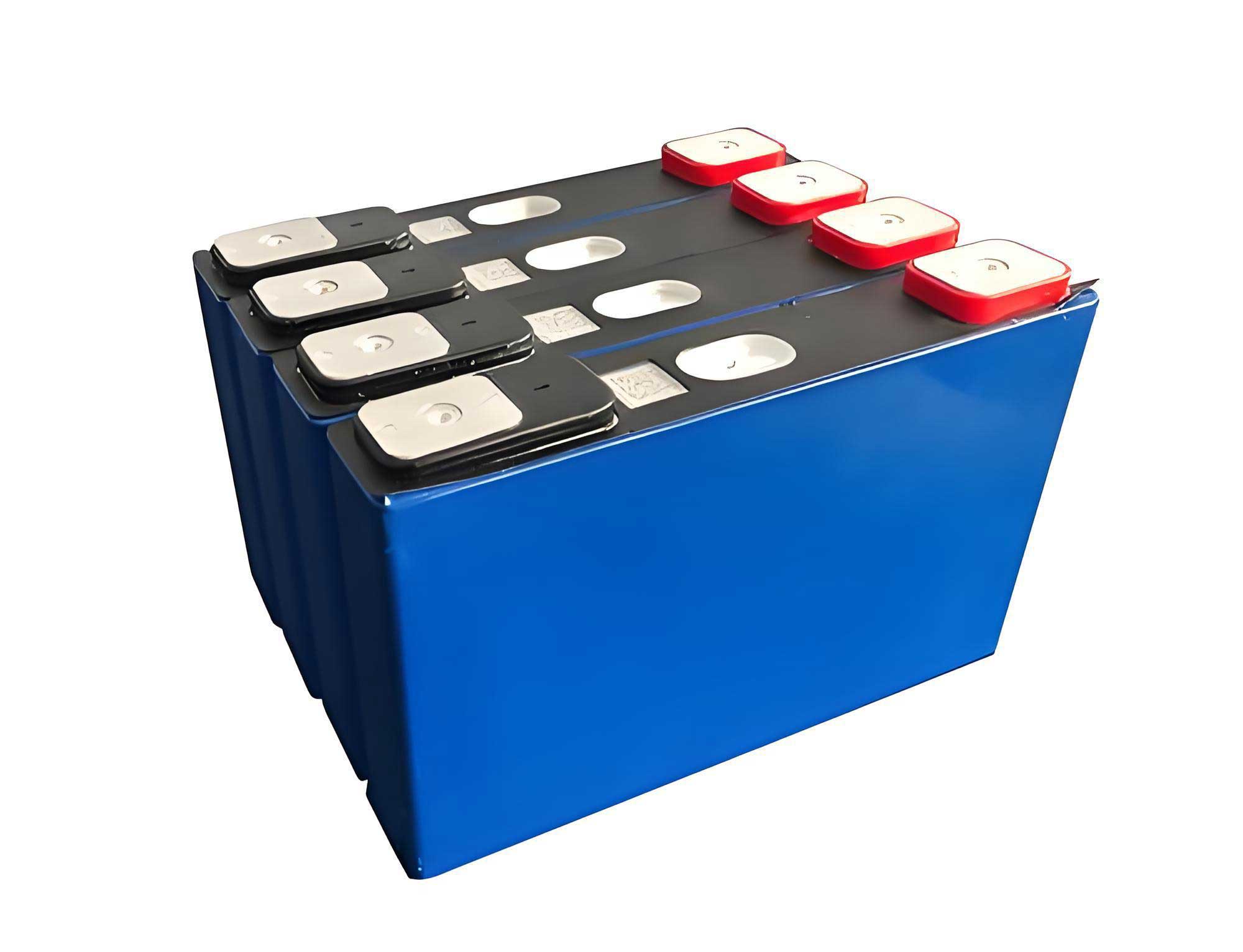
As a researcher focused on electrochemical energy storage safety, I have dedicated significant effort to understanding the complex phenomena of thermal runaway in lithium-ion batteries. Among various chemistries, the **lifepo4 battery** is widely regarded for its intrinsic thermal and chemical stability compared to high-nickel counterparts. However, the assertion of absolute safety is a dangerous misconception. In high-energy-density configurations like those found in grid-scale energy storage systems (ESS), even a **lifepo4 battery** remains susceptible to thermal runaway under abusive conditions. When a single cell undergoes thermal runaway within a densely packed module, the released energy can trigger a cascading failure in adjacent cells—a process known as thermal runaway propagation. This domino effect can escalate a localized cell failure into a module- or even rack-level fire, posing severe risks to property and safety. This article synthesizes experimental findings and analytical models to explore the mechanisms, key influencing factors, and potential mitigation strategies for thermal runaway propagation in **lifepo4 battery** modules.
The fundamental prerequisite for propagation is the occurrence of thermal runaway in an initiating cell. For a **lifepo4 battery**, the thermal runaway mechanism, while occurring at higher temperatures than other chemistries, follows a similar sequence of exothermic reactions. When a cell is subjected to thermal abuse (e.g., external heating, internal short circuit), its temperature rises. Key exothermic reactions include the breakdown of the Solid-Electrolyte Interphase (SEI) layer, reaction between the intercalated lithium and the electrolyte, the decomposition of the electrolyte itself, and finally, the decomposition of the cathode material. The **lifepo4 battery** cathode (LiFePO₄) is notably stable, but at very high temperatures (typically above 300-400°C), it can decompose, releasing oxygen which further fuels reactions with the electrolyte.
The total heat generated during the thermal runaway of a single **lifepo4 battery** cell ($Q_{total, TR}$) can be expressed as the sum of the electrochemical energy released and the chemical reaction heat:
$$Q_{total, TR} = Q_{elec} + Q_{chem}$$
where $Q_{elec}$ is related to the state of charge (SOC) and $Q_{chem}$ is from the material decomposition reactions. A significant portion of this energy is transferred to neighboring cells, primarily through three modes: 1) **Conduction** via physical contact or through interstitial materials/air gaps, 2) **Radiation** from flames and hot surfaces, and 3) **Convection** from ejected hot gases and particles. In a confined module, conduction and radiation from hot cell casings are often the dominant drivers for propagation to the immediately adjacent cells.
The critical question is whether the heat flux received by a neighboring cell ($\dot{q}_{in}$) is sufficient to raise its temperature to its own thermal runaway triggering point before it can dissipate heat ($\dot{q}_{out}$). Propagation occurs if the net energy accumulation leads to the cell reaching its critical temperature. We can frame this using an energy balance for a target cell *i*:
$$
m_i C_{p,i} \frac{dT_i}{dt} = \dot{q}_{in, i}(t) – \dot{q}_{out, i}(t) + \dot{q}_{gen, i}(T)
$$
Here, $m_iC_{p,i}$ is the thermal mass, $\dot{q}_{in, i}$ is the heat influx from the adjacent runaway cell and the environment, $\dot{q}_{out, i}$ is heat loss to other cells and the surroundings, and $\dot{q}_{gen, i}(T)$ is the internal heat generation rate due to the cell’s own exothermic reactions, which becomes significant as $T_i$ increases.
Through extensive experimental testing on commercial 40-100 Ah **lifepo4 battery** modules, several key factors have been quantitatively identified that dramatically influence the propensity and speed of thermal runaway propagation. The relative impact of these factors can be summarized as: **State of Charge (SOC) > Inter-cell Spacing > Electrical Connection Configuration**.
**1. State of Charge (SOC): The Primary Energy Reservoir**
The SOC of a **lifepo4 battery** is the most decisive factor. A fully charged cell contains the maximum amount of electrochemical energy. During thermal runaway, this energy is released, contributing directly to the severity of the event. Higher SOC leads to more violent ejecta, higher peak temperatures, and a greater total heat release, thereby increasing the thermal insult to neighboring cells.
*Table 1: Impact of SOC on Thermal Runaway Propagation in a 40Ah LiFePO4 Module*
| SOC Level | Propagation Outcome | Avg. Peak Cell Temp. | Avg. Mass Loss per Cell | Total Propagation Time (4-cell module) |
| :— | :— | :— | :— | :— |
| **100%** | Full propagation (1→2→3→4) | ~350-440°C | ~193-195 g | ~950-1000 s |
| **50%** | No propagation (only 1st cell fails) | ~230-390°C (1st cell only) | ~181 g (1st cell only) | N/A |
The heat released from the electrochemical energy ($Q_{elec}$) can be approximated by:
$$Q_{elec} \approx \int_{V} \int_{SOC} U_{OCV}(SOC) \cdot d(SOC) \cdot dV$$
where $U_{OCV}$ is the open-circuit voltage, which is a function of SOC. A higher initial SOC provides a larger integral value. In experiments, modules with 50% SOC **lifepo4 battery** cells often fail to propagate after the first cell fails, as the reduced $Q_{total, TR}$ results in $\dot{q}_{in}$ for neighboring cells falling below the critical threshold required to trigger their own runaway.
**2. Inter-cell Spacing: Governing Heat Transfer Resistance**
The distance between cells introduces a thermal resistance, primarily in the conductive and radiative paths. Increasing spacing reduces the view factor for radiation and increases the conductive path length through air or other interstitial materials. The effective heat flux between two adjacent cell walls can be modeled considering conduction across the gap and radiation:
$$\dot{q}_{in}” \approx \frac{T_{hot} – T_{cold}}{R_{gap}} + \sigma \epsilon (T_{hot}^4 – T_{cold}^4)$$
where $R_{gap} = L_{gap} / k_{gap}$ is the conductive resistance of the gap of length $L_{gap}$ and effective conductivity $k_{gap}$, $\sigma$ is the Stefan-Boltzmann constant, and $\epsilon$ is the emissivity. Increasing $L_{gap}$ directly increases $R_{gap}$, reducing the conductive component.
*Table 2: Effect of Cell Spacing on Propagation Dynamics*
| Spacing | Propagation Time (1→4) | Time Interval Between Cell TRs | Dominant Heat Transfer Mode | Mitigation Effectiveness |
| :— | :— | :— | :— | :— |
| **0 mm (Contact)** | ~1000 s | ~300 s | Solid conduction through tabs/casing | Low |
| **1 mm (Air Gap)** | ~1900 s | ~600 s | Radiation & conduction through air | Moderate |
| **≥3 mm (with insulation)** | No propagation / >3000 s | N/A / Very High | Greatly attenuated | High |
Experiments show that even a 1mm air gap can double the total propagation time, providing a crucial window for detection and intervention. This delay arises from the reduced heat transfer coefficient between cells.
**3. Electrical Connection Configuration: Introducing Parasitic Heating**
The way cells are connected (series, parallel, or no connection) significantly alters the failure dynamics during propagation, especially for a **lifepo4 battery** module. When a cell in a parallel-connected pack goes into thermal runaway and its internal resistance plummets due to internal short circuits, it creates a low-resistance path. The remaining healthy, higher-voltage cells then discharge into the failing cell, driving a large current through it. This process, known as “benign” or “malignant” current injection (depending on perspective), introduces substantial **Joule heating** ($Q_{joule}$) in both the failing and the healthy cells.
$$Q_{joule} = \int I(t)^2 \cdot R_{internal}(t) \, dt$$
This additional $Q_{joule}$ can vastly increase the peak temperature and violence of the runaway in the initiating cell and can also pre-heat the connected cells, drastically accelerating propagation.
*Table 3: Comparison of Electrical Connection Effects*
| Connection Type | Key Characteristics During TR Propagation | Peak Cell Temperatures | Propagation Speed | Hazard Severity |
| :— | :— | :— | :— | :— |
| **No Connection** | Pure thermal propagation. Clean voltage drop per cell. | ~350-440°C | Baseline (Reference) | High |
| **Series Connection** | Failing cell opens circuit? Possible re-routing of current. Moderate influence. | Similar to “No Connection” | Similar to or slightly faster than baseline | High |
| **Parallel Connection** | Massive current injection into failing cell. Severe Joule heating. Possible arcing. | Extremely High (>650°C observed) | 3-5x Faster than baseline | Very Severe (Fire/Explosion) |
In parallel configurations, the voltage signature is particularly telling. Instead of dropping to zero, the parallel stack voltage may plateau at a low level as healthy cells continuously dump current into the failing one, sustaining extreme temperatures. This makes parallel-connected **lifepo4 battery** modules particularly vulnerable to catastrophic cascading failures.
Beyond these primary factors, other elements play a role. The **triggering method** (heating, overcharge, nail penetration) influences the initial failure location and violence. **Module enclosure and environment** (confined vs. ventilated) affect gas accumulation and heat dissipation. The **cell format** (prismatic, cylindrical, pouch) influences mechanical stability and heat transfer paths. For a **lifepo4 battery**, the aluminum casing of a prismatic cell provides a good conductive path laterally, which can facilitate propagation if cells are in contact.
The propagation path is often directional and asymmetric. In a linear array, the primary heat transfer path is consistently **towards the downstream cells** (away from the initial trigger point). The upstream cell, having already undergone thermal runaway and now cooling, presents a smaller temperature gradient to the currently failing cell than the cooler, downstream neighbor does. This can be quantified by analyzing the percentage of heat flux from a runaway cell *i* directed forward versus backward.
*Table 4: Analysis of Heat Flow Direction During Propagation*
| Runaway Cell (i) | % Heat to Cell i+1 (Downstream) | % Heat to Cell i-1 (Upstream) | % Heat to Other Paths (Ends, Environment) |
| :— | :— | :— | :— |
| **Cell 1** | ~78% | N/A (No upstream cell) | ~22% |
| **Cell 2** | ~70% | ~17% | ~13% |
| **Cell 3** | ~73% | ~11% | ~16% |
This asymmetry confirms that mitigation efforts should focus most on interrupting the downstream thermal pathway.
Effective safety for **lifepo4 battery** energy storage systems hinges on a multi-layered strategy: prevention, early detection, propagation delay/suppression, and containment.
**1. Early Detection and Warning:**
Thermal runaway is preceded by subtle signatures. Monitoring these can provide critical warning minutes before violent failure.
* **Voltage Monitoring:** A gradual voltage drop of ~0.1-0.2V, followed by a rapid plunge (e.g., to <2.5V for a **lifepo4 battery**), is a reliable indicator of internal short circuit development.
* **Temperature Differential:** Monitoring temperature differences between cells ($\Delta T$) within a module. A sudden rise in one cell relative to its neighbors is a clear warning sign.
* **Gas Detection:** Sensors for volatile organic compounds (VOCs), CO, or hydrogen can detect off-gassing that occurs before thermal runaway.
* **Pressure/Deformation Sensing:** Detecting cell swelling or a rise in module internal pressure.
**2. Passive Mitigation through Design:**
These are intrinsic design features that delay or prevent propagation without external intervention.
* **Optimal Cell Spacing:** Incorporating designed gaps (>3mm) between cells is one of the simplest and most effective methods to increase thermal resistance.
* **Thermal Barriers:** Placing intumescent or phase-change materials between cells. These materials absorb large amounts of heat during decomposition or phase change, protecting adjacent cells.
* **Fire-Resistant Encapsulation:** Filling interstitial spaces with thermally insulating but electrically non-conductive materials (e.g., specialized foams, aerogels) to block heat and flame transfer.
* **Cell-to-Cell Isolation:** Using individual cell housings with integrated thermal insulation.
**3. Active Mitigation Systems:**
These systems respond to a detected fault.
* **Advanced Battery Management Systems (BMS):** A BMS that can implement hierarchical control—disconnecting parallel strings, opening contactors—upon detecting a failing cell is crucial to prevent current injection.
* **Targeted Cooling:** Directing coolant or fire suppressant to the specific overheating cell or module.
* **Ventilation and Gas Management:** Rapidly venting flammable gases from the module or enclosure to prevent explosive atmospheres from forming.
**4. System-Level Containment:**
* **Fireproof Module Enclosures:** Designing modules with materials and seals that can contain a single cell’s thermal runaway event, preventing it from breaching the module.
* **Compartmentalization:** At the rack and container level, using firewalls to isolate failing modules.
In conclusion, while the **lifepo4 battery** chemistry offers a robust foundation for safety, the risk of thermal runaway propagation in large-scale energy storage systems is a critical engineering challenge that cannot be ignored. The propagation is a thermally driven process whose dynamics are dominantly influenced by the **state of charge** of the cells, the **inter-cell spacing** which governs heat transfer, and the **electrical connection scheme** which can introduce debilitating parasitic heating. Understanding the asymmetric, downstream-directed nature of the primary heat transfer path is key to designing effective countermeasures. A holistic safety approach combining careful module design (with spacing and barriers), sophisticated monitoring for early detection (focusing on voltage and temperature anomalies), and responsive control systems (to electrically isolate faults) is essential. By integrating these layers of protection, the inherent safety advantages of the **lifepo4 battery** can be fully leveraged, enabling the safe and reliable deployment of the large-scale energy storage systems vital for our renewable energy future.