
The rapid advancement of the global energy transition, driven by ambitious carbon neutrality goals, has propelled electrochemical energy storage, particularly lithium-ion battery technology, to the forefront. Among the various cathode chemistries, lithium iron phosphate (LiFePO4) batteries have emerged as a preferred choice for large-scale stationary energy storage systems due to their inherent thermal stability, long cycle life, and cost-effectiveness. However, the pursuit of higher energy density and larger system capacities inevitably concentrates significant amounts of electrochemical energy within a confined space. This raises paramount safety concerns, as under abusive conditions such as thermal, mechanical, or electrical stress, a lifepo4 battery can undergo a catastrophic failure process known as thermal runaway (TR). This self-accelerating exothermic reaction, once initiated in a single cell, can propagate to neighboring cells within a module or pack, leading to fire, explosion, and the complete loss of system functionality. Therefore, a comprehensive understanding of the thermal runaway characteristics and, more critically, the propagation mechanisms within a large-format lifepo4 battery pack is essential for designing effective safety mitigation strategies.
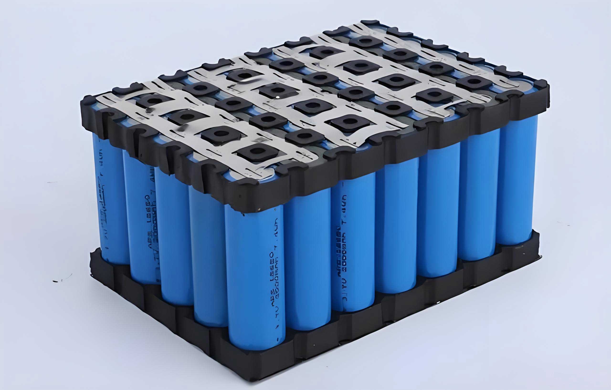
This study focuses explicitly on the thermal safety of large-capacity LiFePO4 battery modules. We adopt an integrated approach combining experimental testing and high-fidelity numerical simulation to investigate the surface temperature evolution during thermal runaway propagation. A detailed three-dimensional thermal runaway model is developed and validated against experimental data. Subsequently, this model is employed to analyze the effectiveness of aerogel insulation pads of varying thicknesses in suppressing or delaying thermal runaway propagation. Furthermore, the energy transfer dynamics between cells during a runaway event are scrutinized. The overarching goal is to enhance the predictive accuracy of thermal runaway models, enabling proactive thermal safety assessment during the design phase and ultimately improving the safety integrity of LiFePO4 battery-based energy storage products.
Experimental Investigation of Thermal Runaway Propagation
To establish a foundational understanding of the thermal runaway behavior in a practical module configuration, a controlled experimental study was conducted. The test subject was a module comprising four commercially available, large-capacity lifepo4 battery cells connected in series. Each prismatic cell had a nominal capacity of 230 Ah and a nominal voltage of 3.34 V. The key parameters of the experimental lifepo4 battery are summarized in Table 1.
| Parameter | Value |
|---|---|
| Dimensions (L × W × H) | 174 mm × 54 mm × 207 mm |
| Rated Capacity | 230 Ah |
| Nominal Voltage | 3.34 V |
| Charge/Discharge Cut-off Voltage | 2.5 V / 3.65 V |
| Weight | ~4.185 kg |
| Nominal Energy Density | ~170 Wh/kg |
Prior to testing, all cells were charged to 100% State of Charge (SOC) using a standard constant-current constant-voltage (CC-CV) protocol and then allowed to stabilize at room temperature for 24 hours. The experimental setup was designed to simulate a common thermal abuse trigger: localized overheating. A 900 W flat heater was attached to the large surface area (174 mm × 207 mm) of the first cell (Cell #1) in the module via a thin aluminum plate to ensure uniform heat distribution. The four cells were held in close contact within a fixture. To minimize heat loss to the environment and focus the energy on inter-cell propagation, 6 mm thick aerogel blankets were placed on the inner sides of the fixture. Thin-gauge K-type thermocouples were strategically attached to the surface of each cell to monitor temperature evolution. Specifically, thermocouples were placed at the center of both the heated surface (facing the heater or the previous cell) and the opposite surface (back side) for each lifepo4 battery, resulting in eight measurement points (T1-T8). Heating was applied continuously until the back-side temperature of Cell #1 met the standard criteria for thermal runaway: the temperature exceeded the maximum operating temperature and the temperature rise rate sustained a value ≥ 1 °C/s for more than 3 seconds. At this point, the heater was deactivated.
The experimental results vividly captured the severe nature of thermal runaway in a large-capacity lifepo4 battery module. The process initiated with Cell #1, where concentrated heating led to internal short circuits, first in the left-side jellyroll and subsequently in the right-side one, as evidenced by two distinct temperature spikes on its back surface (T2). The peak temperature recorded on Cell #1’s back surface exceeded 510 °C. The massive heat release from Cell #1 then served as the trigger for the adjacent cells. The thermal runaway propagated sequentially from Cell #1 to Cell #2, then to Cell #3, and finally to Cell #4. Each cell undergoing thermal runaway experienced a violent venting event, where the safety valve opened, ejecting a significant amount of white smoke and electrolyte vapor, which rapidly reduced visibility within the test chamber. The surface temperature profiles, as shown in the experimental data, revealed the rapid temperature escalation associated with each cell’s failure. Notably, the final cell (Cell #4) in the chain reached a peak surface temperature of approximately 645 °C, and its temperature rise was more abrupt without the intermediate plateau seen in earlier cells, suggesting a more intense reaction possibly due to cumulative heat buildup within the module.
Development of a Numerical Thermal Runaway Model
To gain deeper insights into the internal heat generation and transfer processes that are difficult to measure experimentally, a three-dimensional multi-physics thermal runaway model was developed using COMSOL Multiphysics software. The model aimed to simulate the coupled electrochemical-thermal behavior during the propagation event. The core of the model is the description of heat generation within a failing lifepo4 battery, which is attributed to a series of exothermic chemical decomposition reactions. These are typically modeled using Arrhenius-type equations.
The total heat generation rate per unit volume, $$Q_{tot}$$, is the sum of the heat from four major side reactions:
$$ Q_{tot} = Q_{sei} + Q_{ne} + Q_{pe} + Q_{ele} $$
Where:
- $$Q_{sei}$$ is the heat from the decomposition of the Solid Electrolyte Interphase (SEI) layer.
- $$Q_{ne}$$ is the heat from the reaction between the lithiated anode (negative electrode) and the electrolyte.
- $$Q_{pe}$$ is the heat from the decomposition of the cathode (positive electrode, LiFePO4) with the electrolyte.
- $$Q_{ele}$$ is the heat from the decomposition of the electrolyte itself.
The reaction kinetics for each step are described below:
1. SEI Decomposition:
$$ R_{sei} = A_{sei} \exp\left(-\frac{E_{a,sei}}{RT}\right) c_{sei}^{m_{sei}} $$
$$ \frac{dc_{sei}}{dt} = -R_{sei} $$
$$ Q_{sei} = H_{sei} \cdot W_{sei} \cdot R_{sei} $$
2. Anode-Electrolyte Reaction:
$$ R_{ne} = A_{ne} \left( \frac{t_{sei}}{t_{sei,ref}} \right) \exp\left(-\frac{E_{a,ne}}{RT}\right) c_{ne}^{m_{ne}} $$
$$ \frac{dt_{sei}}{dt} = R_{ne} $$
$$ \frac{dc_{ne}}{dt} = -R_{ne} $$
$$ Q_{ne} = H_{ne} \cdot W_{ne} \cdot R_{ne} $$
3. Cathode-Electrolyte Reaction:
$$ R_{pe} = A_{pe} \alpha (1 – \alpha) \exp\left(-\frac{E_{a,pe}}{RT}\right) $$
$$ \frac{d\alpha}{dt} = -R_{pe} $$
$$ Q_{pe} = H_{pe} \cdot W_{pe} \cdot R_{pe} $$
4. Electrolyte Decomposition:
$$ R_{ele} = A_{ele} \exp\left(-\frac{E_{a,ele}}{RT}\right) c_{ele}^{m_{ele}} $$
$$ \frac{dc_{ele}}{dt} = -R_{ele} $$
$$ Q_{ele} = H_{ele} \cdot W_{ele} \cdot R_{ele} $$
In these equations, $$A_i$$ is the pre-exponential factor, $$E_{a,i}$$ is the activation energy, $$R$$ is the universal gas constant, $$T$$ is the absolute temperature, $$c_i$$ represents the normalized concentration of reactants or state of charge for a component, $$H_i$$ is the heat release per unit mass of reactant, and $$W_i$$ is the mass fraction of the reactant per unit volume. The parameter $$\alpha$$ represents the conversion rate of the cathode material.
This heat source is coupled with the transient heat conduction equation within the battery and module:
$$ \rho c_p \frac{\partial T}{\partial t} = \nabla \cdot (k \nabla T) + Q_{tot} – A_{conv}h(T – T_0) $$
Where $$\rho$$, $$c_p$$, and $$k$$ are the density, specific heat capacity, and anisotropic thermal conductivity tensor of the battery components, respectively. The last term represents convective heat loss to the ambient environment at temperature $$T_0$$, with $$h$$ being the convective heat transfer coefficient and $$A_{conv}$$ the exposed surface area. Several simplifying assumptions were made: the model is homogeneous within each component, ignores the effects of flaming combustion and mass ejection during venting, and considers only the chemical reaction heat, neglecting reversible electrochemical heat. The critical thermophysical properties and reaction kinetics parameters used for the lifepo4 battery model are listed in Tables 2 and 3.
| Component | Density, $\rho$ (kg/m³) | Specific Heat, $c_p$ (J/(kg·K)) | Thermal Conductivity, $k$ (W/(m·K)) |
|---|---|---|---|
| Cell (Jellyroll, anisotropic) | 2151.3 | 935 | $k_x$=18, $k_y$=1.5, $k_z$=18 |
| Cell Case (Aluminum) | 2700 | 880 | 130 |
| Busbar | 1730 | 893 | 180 |
| Aerogel Pad | 190 | 735 | 0.035 |
| Reaction | Heat Release, $H_i$ (J/kg) | Reactant Content, $W_i$ (kg/m³) | Pre-exp. Factor, $A_i$ (s⁻¹) | Activation Energy, $E_{a,i}$ (J/mol) |
|---|---|---|---|---|
| SEI Decomposition | 7.2076×10⁵ | 413 | 1.7×10¹⁵ | 1.14005×10⁵ |
| Anode-Electrolyte | 8.9957×10⁵ | 413 | 2.5×10¹³ | 1.16583×10⁵ |
| Cathode-Electrolyte | 2.527×10⁵ | 925 | 6.7×10¹³ | 1.25983×10⁵ |
| Electrolyte Decomposition | 1.6×10⁵ | 500 | 5.14×10²⁵ | 2.7×10⁵ |
The simulation results for the baseline case (no inter-cell insulation) showed good agreement with the experimental temperature measurements at key locations. The model successfully captured the sequential propagation of thermal runaway, the timing of temperature surges, and the approximate peak temperatures. While there were minor deviations (typically within 10-11% for peak temperatures), attributed to parameter uncertainties and model simplifications, the overall trends were accurately reproduced. This validated model serves as a reliable digital twin for conducting parametric safety studies.
Analysis of Thermal Runaway Propagation and Mitigation with Aerogel Pads
With the validated model, we can dissect the propagation mechanism and evaluate mitigation strategies. The simulation provides a detailed view of the internal temperature field. The process begins with heat accumulation in Cell #1 from the external heater. Once its internal temperature crosses a critical threshold, the exothermic side reactions are triggered, leading to a violent temperature spike. This heat is conducted and radiated to the adjacent surface of Cell #2. For propagation to occur, the heat flux into Cell #2 must be sufficient to raise its internal temperature to the point where its own exothermic reactions become self-sustaining. The simulation reveals that the large thermal mass and the anisotropic conduction within the lifepo4 battery (lower through-plane conductivity) create a delay, but once the neighboring cell’s core reaches criticality, it fails rapidly, releasing its own stored energy and propelling the cascade.
A primary focus of this research was to assess the effectiveness of passive insulation in blocking this propagation path. Aerogel, known for its exceptionally low thermal conductivity, was selected as the interstitial material. We simulated the insertion of thin aerogel pads between the large faces of the lifepo4 battery cells within the module. Two pad thicknesses were investigated: 0.7 mm and 1.2 mm.
The simulation outcomes were clear and significant. The inclusion of an aerogel pad fundamentally altered the heat transfer dynamics between cells. In the baseline case without insulation, the heat flux from a runaway cell was more than sufficient to trigger its neighbor. With the aerogel pad in place, its high thermal resistance drastically reduced the heat flux entering the adjacent lifepo4 battery.
Key Findings on Aerogel Mitigation:
- Propagation Arrest: Both the 0.7 mm and 1.2 mm thick aerogel pads were effective in preventing the complete thermal runaway cascade under the simulated conditions. While Cell #1, directly heated, still underwent thermal runaway, the propagation to Cell #2 was either significantly delayed or entirely halted before Cell #2 could enter a full, self-sustaining runaway state.
- Peak Temperature Reduction: Increasing the thickness of the aerogel pad provided better insulation. The peak temperature reached on the protected surface of Cell #2 was substantially lower with the 1.2 mm pad (∼183 °C) compared to the 0.7 mm pad (∼238 °C).
- Energy Transfer Analysis: The most insightful finding relates to the energy balance within the protected cell. In the case with insulation, Cell #2 receives heat from the runaway of Cell #1 but also loses heat to its other side and to the environment. The simulation indicates that with the aerogel pad, the net energy input into Cell #2 is insufficient to drive its internal temperature high enough to complete the sequence of exothermic reactions. The reactions may initiate partially but cannot reach the critical, autocatalytic stage required for full thermal runaway. Consequently, the reaction arrests itself at an intermediate point. This means the protected lifepo4 battery experiences severe heating and possibly some internal damage but avoids the complete catastrophic energy release that characterizes thermal runaway.
This mechanism highlights the importance of not just delaying the temperature rise but of ensuring the heat flux into a cell remains below the critical threshold needed to activate all reaction pathways. The aerogel pad acts as a thermal current limiter.
Conclusions and Implications for LiFePO4 Battery Pack Safety
This integrated experimental and numerical study on large-capacity LiFePO4 battery modules provides critical insights into thermal runaway propagation and its mitigation. The experimental work confirmed the severe hazard, with peak surface temperatures exceeding 600 °C and sequential failure leading to complete module destruction. The developed and validated high-fidelity thermal runaway model proved to be a powerful tool for deconstructing this complex multiphysics event.
The core conclusion is that passive thermal insulation using ultra-low conductivity materials like aerogel is a highly promising strategy for enhancing the safety of lifepo4 battery packs. Even relatively thin pads (0.7-1.2 mm) can effectively decouple the thermal linkage between cells, preventing or arresting the propagation cascade. The thickness of the insulation directly influences the level of protection, with thicker pads providing greater thermal resistance and lower temperatures in adjacent cells.
From a design perspective, these findings are invaluable. They enable safety engineers to perform virtual “what-if” analyses during the module design phase. By integrating such a model, one can optimize the placement and specification of insulation materials, evaluate different cell spacings, and assess the impact of thermal management system failures. For a lifepo4 battery system intended for large-scale energy storage, where reliability and safety are non-negotiable, such predictive capability is essential for risk reduction.
Future work should expand on this foundation. Experimental validation of the aerogel mitigation effect is a logical next step. Furthermore, the model can be extended to study other factors influencing propagation, such as state of charge (SOC), module enclosure design, and the interaction with active thermal management systems (e.g., cooling plates). Combining robust cell-level design, intelligent battery management systems, and module-level propagation barriers like aerogel insulation represents a holistic approach to ensuring the safe deployment of large-format lifepo4 battery energy storage systems in our future grid.