
In terms of investment and maintenance costs, as well as environmental impact, concrete energy storage systems have enormous potential in the field of high-temperature energy storage applications. Concrete, as a solid sensible heat energy storage material, is an ideal choice. It is easy to obtain and operate, with abundant material sources and lower costs. In addition, its high-temperature stability and durability have also been verified [100, 101]. Therefore, this chapter mainly studies the optimization design of concrete energy storage systems.
The thermal performance of concrete energy storage systems is mainly measured by the heat storage and release time, energy storage, and energy storage efficiency. There are many factors that affect the thermal performance of the system, including system structure, operating parameters, and material thermal properties parameters.
Previous studies mainly used parameter analysis methods to investigate the impact of individual influencing factors on the thermal performance of energy storage systems. However, these influencing factors are not independent and may interact with each other, which can significantly affect the thermal performance of energy storage systems.
In order to better design concrete energy storage systems, it is necessary to determine the variables that have a significant impact on the system’s thermal storage performance and their interactions, and establish a functional relationship between the influencing factors and thermal performance indicators. Based on the established three-dimensional concrete sensible heat energy storage system model, the temperature distribution of each part during the heat storage and release process of the concrete energy storage system unit was observed over time, and the thermal performance indicators were calculated.
Five variables, including the number of fins and pipes, fluid inlet temperature, flow rate, and initial system temperature, were selected as design variables that affect the energy storage effect of the concrete energy storage system. Three variables, namely heat storage time, energy storage, and energy storage efficiency, were selected as response variables. Generate 27 sets of simulations based on central composite rotation design, and establish a quadratic regression model between influencing factors and response index values. The impact of each influencing factor and their interaction on the response value can be obtained through the analysis of variance method. Finally, taking the minimum heat storage time, maximum energy storage, and maximum heat storage efficiency as joint optimization objectives, the expected function is used to obtain the parameter combination that satisfies the optimal situation. Based on the optimized parameter combination, reference is provided for the design and operation of concrete energy storage systems.
1. Energy storage system unit design
The energy storage system adopts a cylindrical geometric structure, with concrete as the thermal storage matrix and heat transfer pipelines embedded inside. To increase the thermal conductivity of the system, fins are added to the pipeline. High temperature fluid flows into the system through the left end of the pipeline, undergoes convective heat exchange with the pipe wall and transfers heat to the concrete, and then the low-temperature fluid flows out from the right end of the pipeline. Considering the symmetry of the model, only half of the model is used to calculate the temperature field of the thermal storage system during simulation, which can improve calculation efficiency and save calculation time.
The economic benefits of concrete energy storage systems are closely related to the technical characteristics of energy storage systems. High heat storage and efficient heat transfer efficiency can significantly reduce the volume of energy storage systems, thereby reducing the cost of energy storage systems. Increasing the number of heat transfer pipelines can reduce the time required for heat storage, but it also reduces the amount of concrete used. However, due to the relatively high cost of stainless steel pipes, it is necessary to balance the relationship between the quantity of use and efficiency. In order to achieve rapid heat conduction and allow heat to quickly transfer to concrete, it is necessary to install fins on the pipeline, which can expand the range of heat conduction.
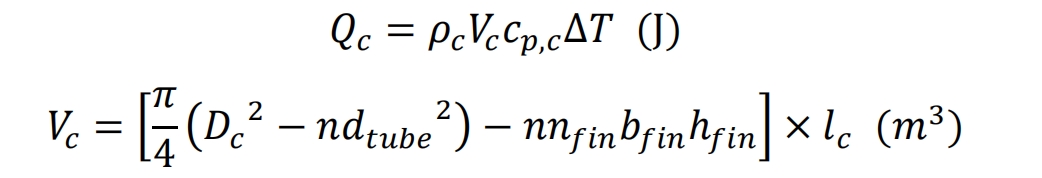
The energy storage system uses concrete as the heat storage medium. Due to the relatively abundant air resources and low cost, air is chosen as the heat transfer fluid. For the current concrete energy storage system, design a storage capacity of 50MJ and determine a temperature range of ∆ T=60 ℃. The amount of concrete required by the system can be calculated according to the formula. The length of the energy storage system is 1.8m, and the diameter of the system is calculated by the formula, resulting in a length of 0.629m. The outer diameter of the heat transfer pipeline is 0.015m, the thickness is 0.0015m, and the fin height and thickness are 0.02m and 0.002m, respectively.
In the formula, 𝑄𝑐 is the energy storage capacity of concrete, J; 𝜌𝑐 is the density of concrete, kg/m ^ 3; 𝑉𝑐 is the volume of concrete, m ^ 3; 𝑐𝑝, 𝑐 is the specific heat of concrete, J/(kg · K); ∆ 𝑇 is the temperature range, ℃; 𝐷𝑐 is the diameter of the concrete energy storage system unit, m; 𝑛 is the number of heat transfer pipelines; 𝑑𝑡 ube is the diameter of the heat transfer pipeline, m; 𝑛𝑓 in is the number of fins; 𝑏𝑓 in is the thickness of the fins, m; ℎ𝑓 in is the height of the fins, m; 𝑙𝑐 is the length of the concrete energy storage system unit, in meters.
2. Unit simulation of concrete energy storage system
The concrete thermal storage unit uses COMSOL Multiphysics 5.5 software to solve the control equations. The continuity equation, Navier Stokes equation, and energy conservation equation of the energy storage system unit are solved using the PARDISO solver, while the Euler backward difference formula (BDF) is used for time stepping. By adjusting the transient solver, the convergence of the model can be improved. When setting up a transient model, for the fluid flow model in the pipeline, the initial velocity of the fluid at the inlet of the pipeline is greater than 0m/s, but the velocity value inside the pipeline is 0m/s. The initial values of the two do not match, which can lead to inconsistent initial values and non convergence of the last step size. Here, a step function is used to smooth the inlet flow velocity of the fluid, gradually increasing the boundary conditions. Starting from zero, the inlet flow velocity of the fluid is stepped, and a smaller time step is selected to improve convergence. Due to the highly nonlinear nature of the multi physics field coupling solution problem, iterative solution calculation is adopted. When the residual of the iterative solution result is small enough, it can be considered that the result converges to the specified tolerance. This article sets the convergence standard for the solution to be less than 10 ^ -3, that is, it converges when the iterative residual of the concrete temperature field is less than 10^-3.
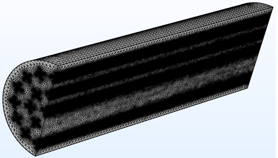
In order to reduce the computational time while ensuring the accuracy of the calculation results, the grid analysis of the three-dimensional concrete energy storage system unit model is carried out using a user controlled grid method. The domain and adjacent boundary geometric structures in the model are divided using free tetrahedral and free triangular grids, respectively. Because most of the geometric domains in the concrete energy storage system units only require a small number of grid elements to meet the computational accuracy requirements, this article uses free tetrahedral meshes to set up the concrete domain and heat transfer fluid domain, while the free triangular meshes are used to set up the interface between the fluid domain and the heat transfer pipeline, as well as the interface between the concrete and the heat transfer pipeline and fins. Refine the mesh at the contact interface to make the calculation results more accurate. In the grid setting, the maximum cell size is 25mm, the minimum cell size is 3mm, the maximum cell growth rate is 1.35, and the curvature factor is 0.55. The mesh geometry of the concrete energy storage system unit (when there are four fins on the heat transfer pipeline) is shown in Figure 1, from which it can be seen that the mesh at the contact interface of different materials is densified.
The independence of the number of grids selected for simulation calculation needs to be verified by performing multiple simulations to check for changes in simulation results caused by differences in the number of grids. The simulation of heat storage process compares four different grid quantities with 2057894, 4770076, 4779237, and 8984467 grid elements. The average temperature of concrete over time in four different grid energy storage system models is shown in Figure 2.
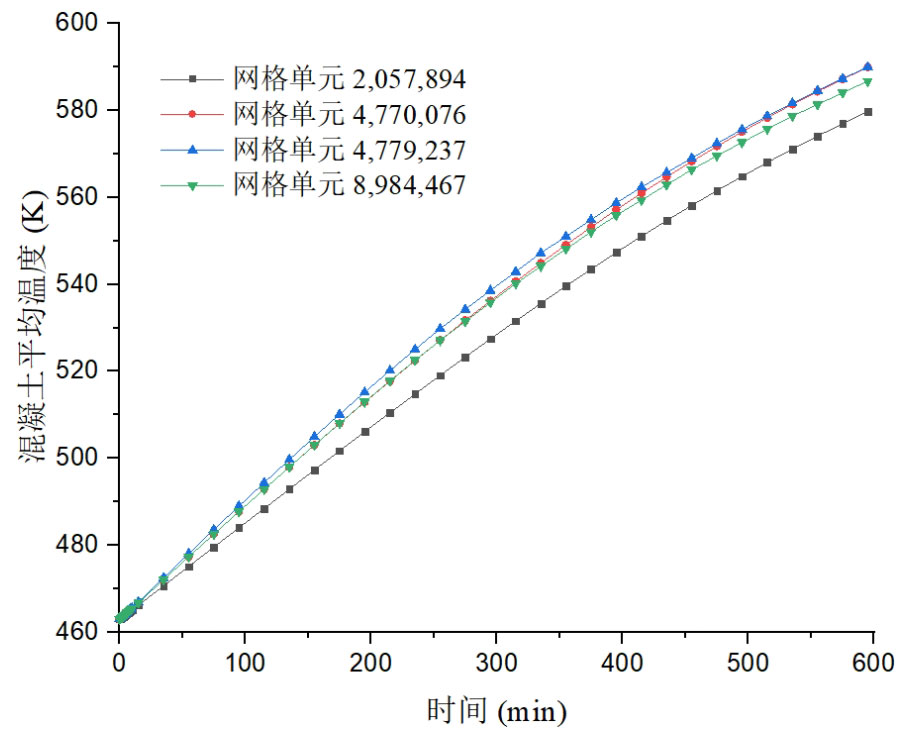
From the results on the graph, it can be seen that when the number of grids is 2057894, the average temperature change of the concrete energy storage system unit is significantly different from the other three situations. When the number of grids increased from 4770076 to 4779237, there was no significant change in the average temperature curve of concrete. As the number of grids continues to increase to 8984467, the difference in average temperature variation of concrete remains small. Therefore, in order to improve computational speed and save computational costs, it can be considered that the number of model grids ranges from 4770076 to 4779237, and the average temperature change of the model is independent of the number of grids. The conclusion drawn is to select 4770076 grids for numerical simulation.
Through the process, the temperature field of the thermal storage unit at the end of the thermal storage process can be obtained. When the temperature field of the concrete thermal storage medium reaches convergence accuracy, that is, the calculation ends when the temperature field iteration residual is less than 10 ^ -3. Then, based on the temperature distribution and heat storage time in the energy storage system unit, calculate thermal performance indicators such as heat storage capacity and heat storage efficiency.