
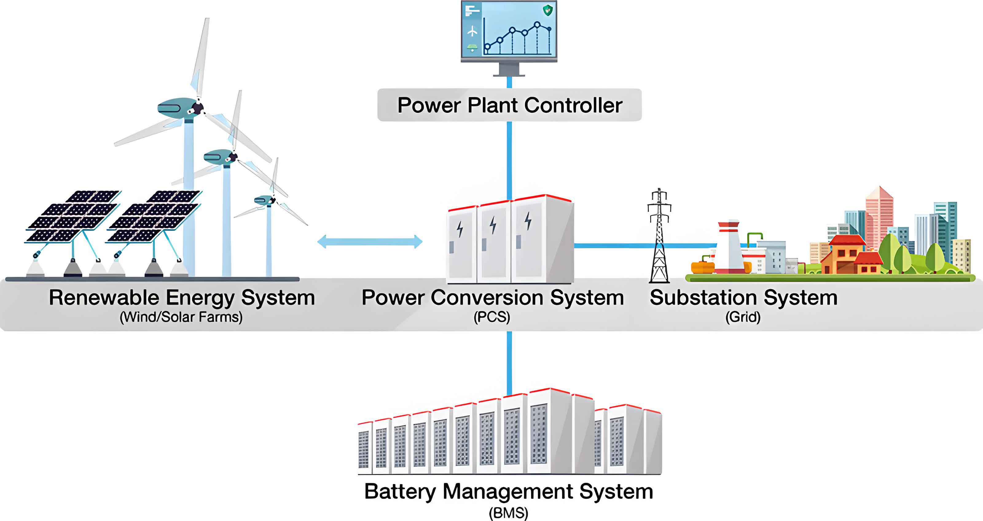
As the global energy landscape shifts decisively towards decarbonization, the integration of renewable energy sources like wind, solar, and hydro power has become a central pillar of modern power systems. However, the inherent intermittency and distributed nature of these sources often lead to grid instability, historically rendering such power as challenging to manage. The advent of advanced energy storage technologies has fundamentally transformed this paradigm. Among these, electrochemical storage, particularly lithium-ion battery-based systems, has emerged as a cornerstone for grid-scale applications due to its modularity, rapid response, and flexibility. The battery energy storage system is thus a critical enabler for load shifting, frequency regulation, and enhancing grid reliability. Nevertheless, the safe and efficient operation of a battery energy storage system is intrinsically linked to its thermal management. During charging and discharging, heat generation from internal resistance and electrochemical reactions can cause temperature rise and spatial inhomogeneity. If not adequately dissipated, this can degrade performance, accelerate aging, and even trigger thermal runaway. For a lithium-ion battery energy storage system, the optimal operating temperature range is typically 293–313 K, with a temperature uniformity preferably within 5 K. Exceeding this differential can reduce cycle life by over 30%. Moreover, temperatures above approximately 393 K pose a severe thermal runaway risk. Therefore, developing effective thermal management solutions is paramount for the longevity, safety, and economic viability of any large-scale battery energy storage system.
This challenge is exacerbated during high-rate and ultra-high-rate charge-discharge cycles, which are increasingly required for grid services like rapid frequency response or absorbing surplus renewable generation. Under such conditions, heat generation intensifies, demanding cooling systems with exceptional heat removal capacity and temperature homogeneity control. While various cooling methods exist—including air cooling, liquid cooling, and phase change cooling—liquid cooling is often favored for its high heat transfer coefficients, stability, and effectiveness in controlling maximum temperature and uniformity within a battery energy storage system. However, most existing liquid cooling designs are optimized for standard operating conditions and may struggle under extreme rates. In this study, I propose and numerically evaluate a novel bidirectional counter-flow heat exchange plate design specifically aimed at addressing the thermal management challenges of a battery energy storage system under high-rate and ultra-high-rate operations. Through comprehensive simulation, I compare this design against two conventional liquid cooling layouts to demonstrate its superior performance in maintaining both temperature limits and uniformity.
The core of this investigation involves three distinct cooling configurations for a representative battery pack within a battery energy storage system. The pack comprises ten series-connected prismatic lithium iron phosphate (LFP) cells, each with a capacity of 135 Ah, nominal voltage of 3.2 V, and dimensions of 945 mm × 14 mm × 90 mm. The anisotropic thermal conductivity of the cell is a key consideration: 18.3 W/(m·K) in the planar (x, z) directions and 1.1 W/(m·K) in the thickness (y) direction. The three cooling schemes are:
Scheme 1 (Bottom Cooling): A traditional single-direction, straight-channel cold plate is placed at the bottom of the battery pack. Coolant flows from one inlet to an outlet, removing heat primarily through the bottom surface of the cells.
Scheme 2 (Side Unidirectional Cooling): Single-direction, straight-channel cold plates are inserted between the large side surfaces of adjacent cells. This increases the contact area and shortens the heat conduction path compared to bottom cooling.
Scheme 3 (Side Bidirectional Counter-Flow Cooling): This is the proposed novel design. Bidirectional counter-flow plates are placed between cells. Each plate features two inlets at the bottom and two outlets at the top, creating symmetric, interdigitated flow channels where two coolant streams flow in opposite, crossing directions. An air gap layer is also incorporated between adjacent plates to provide thermal insulation between cooling units.
In all schemes, a thin layer of thermal interface material (e.g., thermal grease) is assumed between the cells and cold plates to ensure good thermal contact. The coolant is a 50% ethylene glycol-water mixture with an inlet temperature of 293.15 K and a total flow rate of 12 L/min distributed across the system.
The mathematical modeling of the battery energy storage system’s thermal behavior rests on several fundamental equations. The heat generation rate within each lithium-ion cell is calculated using the Bernardi model:
$$ q = \frac{I}{V_b} \left[ (E_0 – U) – T \frac{dE_0}{dT} \right] = \frac{1}{V_b} \left( I^2 R – I T \frac{dE_0}{dT} \right) $$
where \( q \) is the volumetric heat generation rate (W/m³), \( I \) is the current (A), \( V_b \) is the battery volume (m³), \( E_0 \) is the open-circuit voltage (V), \( U \) is the terminal voltage (V), \( T \) is the absolute temperature (K), and \( R \) is the internal resistance (Ω). This model accounts for both irreversible (Joule) heating and reversible (entropic) heating effects.
The three-dimensional, anisotropic heat conduction within the cell is governed by:
$$ \rho C_p \frac{\partial T}{\partial t} = \lambda_x \frac{\partial^2 T}{\partial x^2} + \lambda_y \frac{\partial^2 T}{\partial y^2} + \lambda_z \frac{\partial^2 T}{\partial z^2} + Q $$
Here, \( \rho \) is density (kg/m³), \( C_p \) is specific heat capacity (J/(kg·K)), \( \lambda_x, \lambda_y, \lambda_z \) are the thermal conductivities along the principal axes (W/(m·K)), and \( Q \) is the heat source term equal to \( q \). For steady-state simulations comparing the cooling schemes, the transient term is zero.
The fluid flow and heat transfer in the cold plates and coolant are described by the continuity, momentum (Navier-Stokes), and energy equations for an incompressible fluid:
$$ \nabla \cdot \vec{v} = 0 $$
$$ \rho_w \left( \frac{\partial \vec{v}}{\partial t} + (\vec{v} \cdot \nabla) \vec{v} \right) = -\nabla p + \mu \nabla^2 \vec{v} + \rho_w \vec{g} $$
$$ \rho_w C_{pw} \left( \frac{\partial T_w}{\partial t} + \vec{v} \cdot \nabla T_w \right) = k_w \nabla^2 T_w $$
where \( \vec{v} \) is velocity (m/s), \( p \) is pressure (Pa), \( \rho_w \) and \( \mu \) are coolant density and dynamic viscosity, \( \vec{g} \) is gravity, \( C_{pw} \) is coolant specific heat, \( T_w \) is coolant temperature, and \( k_w \) is coolant thermal conductivity. The energy equation for the solid cold plate (subscript \( n \)) is:
$$ \rho_n C_{pn} \frac{\partial T_n}{\partial t} = k_n \nabla^2 T_n $$
These equations are solved numerically using a finite volume method. A mesh independence study was conducted to ensure result accuracy. The table below summarizes the pressure drop across the system for different mesh counts, confirming that a mesh size of approximately 4.23 million elements provides a grid-independent solution.
| Number of Mesh Elements (Millions) | Pressure Drop ΔP (kPa) |
|---|---|
| 1.33 | 13.60 |
| 2.36 | 13.90 |
| 2.89 | 14.20 |
| 3.16 | 14.80 |
| 4.23 | 14.90 |
| 5.13 | 14.93 |
Simulations were performed for three discharge rate scenarios representing common and extreme demands on a battery energy storage system: standard rate (1C), high rate (3C), and ultra-high rate (5C). The heat generation parameters scale accordingly with the current. The primary performance metrics are the maximum temperature (\( T_{max} \)) within the battery pack and the maximum temperature difference (\( \Delta T_{max} \)) across all cells. For a reliable battery energy storage system, the goals are \( T_{max} < 313 \, K \) and \( \Delta T_{max} < 5 \, K \).
The results for the standard 1C rate are summarized below. All schemes kept the maximum temperature within acceptable limits, but only Schemes 2 and 3 maintained the required temperature uniformity.
| Cooling Scheme | Maximum Temperature, \( T_{max} \) (K) | Maximum Temperature Difference, \( \Delta T_{max} \) (K) | Meets \( T_{max} < 313K \)? | Meets \( \Delta T_{max} < 5K \)? |
|---|---|---|---|---|
| Scheme 1: Bottom Cooling | 301.0 | 6.5 | Yes | No |
| Scheme 2: Side Unidirectional | 294.7 | 1.5 | Yes | Yes |
| Scheme 3: Side Bidirectional Counter-Flow | 294.0 | 1.0 | Yes | Yes |
Scheme 1’s failure to control temperature difference stems from the long, inefficient heat conduction path from the top of the cells to the bottom cold plate, exacerbated by the cell’s low through-plane thermal conductivity. This creates a significant vertical thermal gradient. In contrast, Schemes 2 and 3, by cooling the large side surfaces, leverage the cell’s higher in-plane conductivity and reduce the conduction distance, achieving excellent uniformity even at this moderate rate.
Under the high-rate 3C condition, which stresses the thermal management of a battery energy storage system during peak grid services, the performance divergence becomes stark.
| Cooling Scheme | Maximum Temperature, \( T_{max} \) (K) | Maximum Temperature Difference, \( \Delta T_{max} \) (K) | Meets \( T_{max} < 313K \)? | Meets \( \Delta T_{max} < 5K \)? |
|---|---|---|---|---|
| Scheme 1: Bottom Cooling | 357.0 | 52.0 | No (Risk High) | No |
| Scheme 2: Side Unidirectional | 307.0 | 13.0 | Yes (Marginally) | No |
| Scheme 3: Side Bidirectional Counter-Flow | 299.0 | 4.8 | Yes | Yes |
Scheme 1 is entirely inadequate, with temperatures approaching the thermal runaway threshold. Scheme 2 manages to keep the maximum temperature just below the upper safety limit but fails to control uniformity, which would lead to accelerated aging. Remarkably, Scheme 3, the bidirectional counter-flow design, successfully maintains both \( T_{max} \) below 299 K and \( \Delta T_{max} \) within the 5 K limit. This demonstrates its robust capability for high-rate operation in a battery energy storage system.
The extreme scenario of a 5C ultra-high rate, though rare, tests the absolute limits of the cooling system. Such conditions might occur during grid faults or very short-duration, high-power events.
| Cooling Scheme | Maximum Temperature, \( T_{max} \) (K) | Maximum Temperature Difference, \( \Delta T_{max} \) (K) | Safety & Practical Assessment |
|---|---|---|---|
| Scheme 1: Bottom Cooling | 470.0 | 107.0 | Catastrophic failure, severe thermal runaway and safety hazard. |
| Scheme 2: Side Unidirectional | 332.0 | 39.0 | \( T_{max} \) exceeds normal range, \( \Delta T_{max} \) very high. Significant performance degradation and aging expected. |
| Scheme 3: Side Bidirectional Counter-Flow | 308.0 | 14.0 | \( T_{max} \) remains safe (well below 393 K), \( \Delta T_{max} \) >5K but acceptable for short-term extreme events. |
Even under this severe stress, the proposed Scheme 3 prevents dangerous temperature escalation. While the temperature difference exceeds the ideal 5 K, the maximum temperature of 308 K is still within a range that avoids immediate thermal runaway risks for short durations. This resilience is crucial for the overall safety architecture of a grid-scale battery energy storage system facing unexpected transients.
The superior performance of the bidirectional counter-flow plate can be understood through analysis of the internal thermal-fluid dynamics. The temperature distribution within the coolant for the 3C case is highly informative. In Scheme 1, the coolant temperature rises monotonically along the flow direction by about 15 K, leading to a warmer outlet region and contributing to pack inhomogeneity. In Scheme 2, a similar but slightly reduced streamwise temperature rise (~10 K) occurs. However, in Scheme 3, the counter-flow mechanism creates a remarkable self-equalizing effect. The two opposing coolant streams exchange heat with each other through the plate material, effectively pre-cooling the warmer fluid and pre-heating the cooler fluid. This results in a much more uniform temperature field within the plate itself, with a spatial temperature variation of only about 1 K. This inherent thermal compensation is the key to its excellent uniformity control. The governing energy exchange can be conceptualized by considering the heat transfer between the two counter-flowing streams. For a differential element, the heat transfer rate \( d\dot{Q} \) can be expressed as:
$$ d\dot{Q} = U_p \cdot A_{contact} \cdot (T_{h,stream} – T_{c,stream}) \, dx $$
where \( U_p \) is an overall heat transfer coefficient for the internal plate structure separating the streams, \( A_{contact} \) is the specific contact area per unit length, and \( T_{h,stream} \) and \( T_{c,stream} \) are the local temperatures of the hotter and cooler streams, respectively. The counter-current arrangement maximizes the log-mean temperature difference along the flow path, leading to efficient internal heat exchange and flattening the temperature profile seen by the battery cells. Furthermore, the incorporated air gap between plates in Scheme 3 prevents thermal cross-talk, ensuring each cooling unit operates independently on its adjacent cell.
The effectiveness of a thermal management system for a battery energy storage system can also be evaluated using a performance coefficient that balances cooling power against pumping power. While a detailed exergy analysis is beyond this scope, a simplified metric \( \eta \) can be defined as the ratio of heat removed from the battery pack to the hydraulic power required:
$$ \eta = \frac{\dot{Q}_{removed}}{P_{pump}} \approx \frac{\sum_{cells} q \cdot V_b}{\dot{V} \cdot \Delta P} $$
where \( \dot{V} \) is the volumetric flow rate and \( \Delta P \) is the system pressure drop. Although Scheme 3 might have a slightly more complex flow path, its superior temperature control at high rates implies a more effective heat removal per unit of pumping energy when preventing thermal runaway is the priority, a critical consideration for the total cost of ownership of a battery energy storage system.
In conclusion, this investigation highlights the critical importance of advanced thermal management for the safe and efficient operation of lithium-ion battery energy storage systems, especially under demanding high-rate conditions. The traditional bottom-cooling approach (Scheme 1) exhibits fundamental limitations due to thermal resistance in the cell’s thickness direction, making it unsuitable for high-power applications. The side-mounted unidirectional cooling (Scheme 2) offers significant improvement but still fails to maintain the required temperature uniformity under high and ultra-high rates, which can compromise the longevity and reliability of the battery energy storage system. The novel side-mounted bidirectional counter-flow heat exchange plate (Scheme 3) represents a substantial advancement. By ingeniously employing a symmetric, counter-current flow channel design, it establishes an internal thermal compensation mechanism that effectively mitigates temperature gradients. This design ensures that even under a 3C high-rate scenario, the battery pack operates with a maximum temperature below 299 K and a temperature difference of only 4.8 K, satisfying both key thermal management criteria. Under an extreme 5C rate, it maintains the maximum temperature at a safe 308 K, demonstrating robust resilience. Therefore, the bidirectional counter-flow cooling strategy provides a highly effective and adaptable technical solution for enhancing the thermal performance, safety, and cycle life of grid-scale battery energy storage systems, enabling them to reliably meet the evolving demands of modern renewable-integrated power grids.