
In photovoltaic power generation systems, the stability of the system is crucial, and solar inverters are an important factor in maintaining this key. The high power, high efficiency, and high reliability of solar inverters can meet the characteristics of photovoltaic power generation systems. There are various classification methods for the structure of solar inverters. This chapter provides a detailed introduction to the classification methods of solar inverters, including DC/DC converters and DC/AC converters. Several common solar inverter topologies are listed in this article, and their advantages, disadvantages, and application scope are analyzed for these widely used topologies. The topology type chosen for this project is provided.
1. Basic topology of solar inverters
There are many methods for dividing solar inverters, and the first method can be macroscopically divided into ordinary solar inverters, specialized solar inverters for postal and telecommunications communication, integrated inverter/control machines, and specialized solar inverters for aerospace and military use; The second method is to classify solar inverters based on frequency, which can be specifically divided into power frequency solar inverters, intermediate frequency solar inverters, and high-frequency solar inverters; The third type can classify solar inverters according to the number of output phases, including single-phase and three-phase; If divided into bidirectional and unidirectional according to the direction of power flow; The classification method for active solar inverters and passive solar inverters is based on the direction of the output energy of the solar inverter; According to the working mechanism of the circuit, it can be divided into PWM mode and harmonic mode; And what we often refer to as single ended solar inverters, push-pull solar inverters, half bridge solar inverters, and full bridge solar inverters are divided according to the form of the main circuit of solar inverters; The voltage source and current source are specifically divided into different types on the DC side of the solar inverter; There are two types of photovoltaic power generation systems: grid connected and off grid, and solar inverters can be divided into off grid and grid connected types; The connection methods on the communication side are different, with two types: isolated and direct; The working frequency of solar inverters varies, which can be divided into high-frequency isolation type and power frequency isolation type. The working mode of switching circuits is different, and solar inverters can also be divided into resonant, fixed frequency hard switching, and fixed frequency soft switching. According to the different positions of power decoupling or DC energy storage capacitors in solar inverters, the types of single-phase high-frequency link solar inverters in photovoltaic power generation systems can be divided into: intermediate DC bus power decoupling, DC input power decoupling, and no power decoupling link. The output voltage or current of solar inverters have different waveforms: square wave solar inverters, stepped wave solar inverters, and sine wave solar inverters. A two-stage inverter system without isolation is adopted, and its structural diagram is shown in Figure 1.
2. Comparison of several common solar inverter topologies
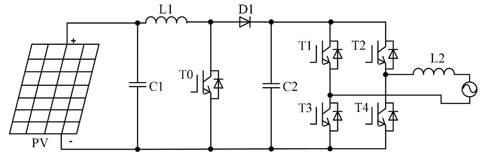
(1) Figure 2 shows the structure of first boosting and then inverting.
The structure diagram of a common solar inverter shown in Figure 2 consists of two stages: a single Boost boost circuit forms its front stage; The secondary circuit consists of a full bridge inverter structure consisting of four power switching tubes. Its characteristic is that the boost factor and power of the front stage cannot be too large, so this topology is more commonly used in small, single-phase grid connected solar inverters and systems with low DC voltage. The advantages of this structure are that the efficiency can reach about 98%, and the cost is not high, the structure is not complex, and the volume does not need to be large, so the weight is relatively light. Its disadvantage is that there is no isolation between input and output, which can have adverse effects on personnel safety and system insulation; In order to prevent the DC component from entering the power grid, it is also necessary to detect and measure the output DC component.
(2) Figure 3 shows the direct inverter output structure.
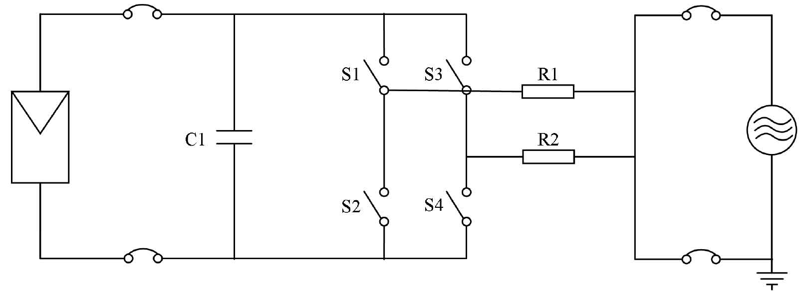
The circuit diagram shown in Figure 3 does not boost the voltage of the battery board. Its advantages are: compared with the first topology structure, solar inverters have a higher input DC voltage and do not require boost control. Therefore, the structure is simpler, the cost is lower, the volume is smaller, the weight is lighter, the efficiency is higher, and even up to about 99%. The higher DC voltage determines its lower current, resulting in lower on state losses and no transformer losses [32-34]. Its disadvantage is that compared to the previous topology, its series voltage needs to be at a higher level, which limits the input voltage range of the solar inverter to not be too low. Additionally, it is required that the power of the solar inverter be relatively high. It is easier to introduce DC components, and in order to prevent DC components from entering the power grid, it is also necessary to detect and measure the output DC components.
(3) Figure 4 shows a structure with high-frequency transformer isolation, where high-frequency inverter is used for boosting and rectifying before inverter output.
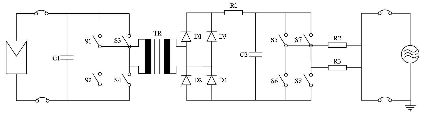
The working principle of the topology structure in Figure 4 is as follows: first, high-frequency inverter is used to boost voltage, then rectified into high-voltage DC, and finally inverter output at a higher DC voltage. Its advantages are: efficiency can reach about 96%, lightweight, small size, low cost, and will not affect the grounding of the system. Its disadvantage is that due to factors such as high-frequency transformer cores, the output can only be used for small solar inverters. In addition, DC component detection must be added to control the DC component to avoid injecting it into the power grid.
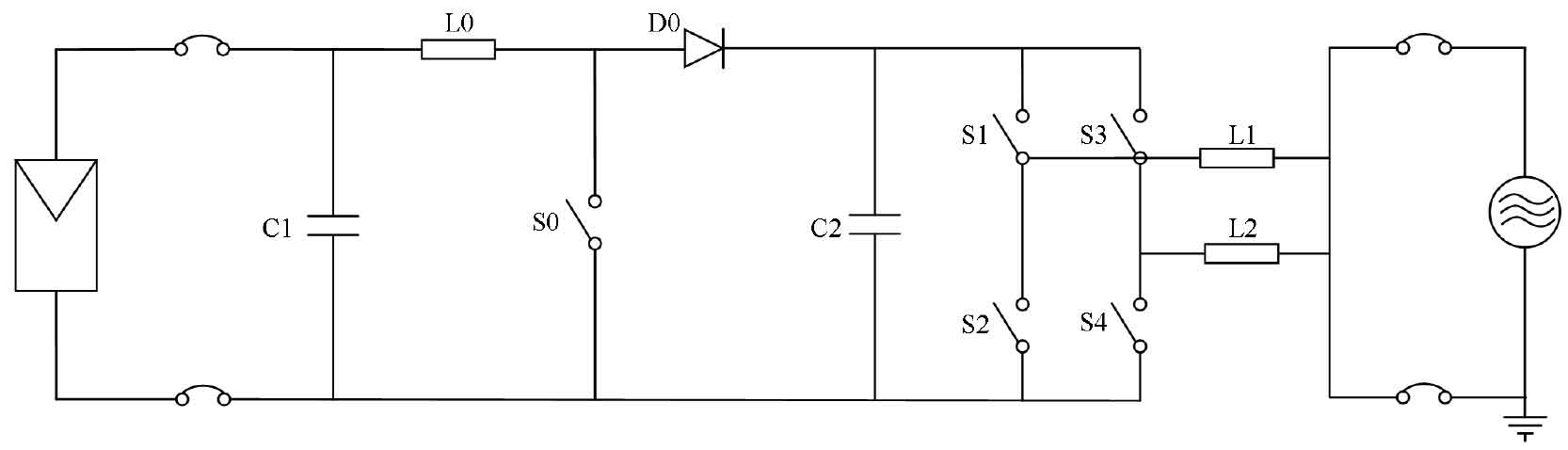
(4) Figure 5 shows the isolated output structure of inverter followed by boost.
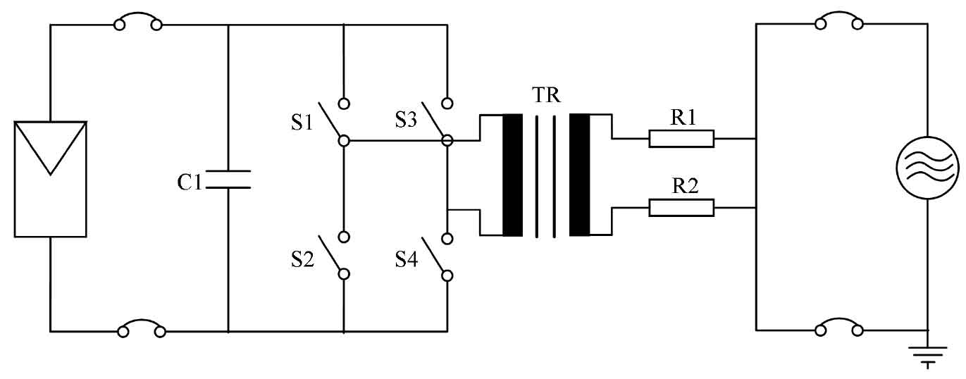
The topology shown in Figure 5 is widely used in grid connected solar inverters, with the advantages of not affecting system grounding and insulation, and not requiring detection and control of the DC component on the AC output side. Its disadvantages are: inverting on the DC low-voltage side, low voltage, high current, high pass loss, and switching loss; The power transformer has losses, and the overall efficiency of the solar inverter is not high, with a maximum value of about 96%.
(5) Figure 6 shows the direct inverter output, which is fed into the high-voltage power grid structure through a power transformer.
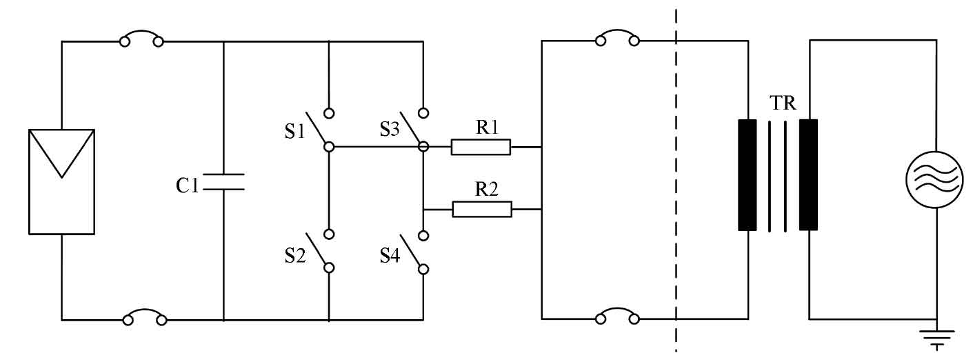
The topology shown in Figure 6 is widely used in large-scale grid connected systems, with the advantages of greatly improving the operational efficiency of the power grid, saving costs, and facilitating the selection of transformers suitable for local grid voltage.
(6) Figure 7 shows the structure of a multi-channel MPPT input solar inverter.
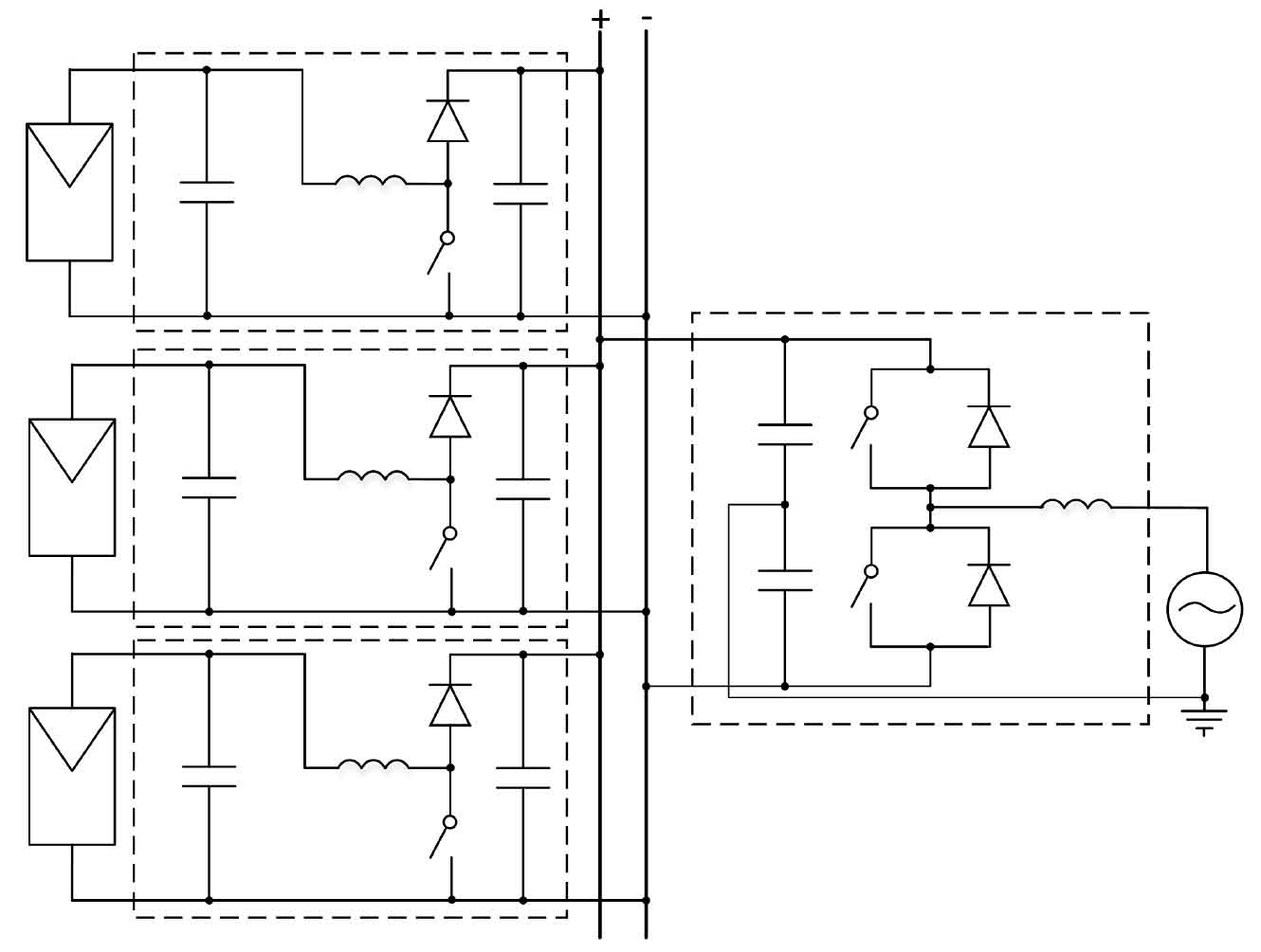
The advantage of this circuit diagram is that it is suitable for multiple different inclined plane arrays or different components due to the presence of multiple DC-DC circuits with different MPPT input circuits; In the case of parallel connection of solar cell modules, the energy loss caused by the discreteness of solar cell module parameters or differences in solar radiation conditions can be overcome, and the power generation of the system can be increased by about 3% -10%. For photovoltaic building projects, this system structure diagram can leverage its advantages. Its disadvantage is that there is no isolation between the input and output, which can have adverse effects on the insulation of the system and the safety of personnel. In order to prevent the DC component from entering the power grid, it is also necessary to detect and measure the output DC component.
(7) Figure 8 shows the structure of the inverter system from the inverter unit structure.
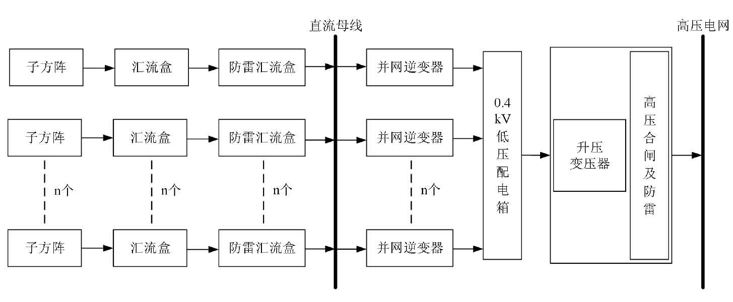
The advantage of this structure is that it is very helpful for improving the efficiency of system operation, and the no-load loss is also small. According to the intensity of external lighting, the group controller automatically switches one by one, and reasonably controls the number of power supplies put into operation, so that each power supply operates at a higher load rate, which can effectively improve the efficiency of the system. Disadvantages include: The system connects the entire array through a DC bus, and due to differences in solar cell module parameters or solar radiation conditions, energy loss of the array in parallel can occur.
When solar photovoltaic power plants are built, this difference may be small, but as the usage time prolongs, this difference will also increase. In large-scale solar photovoltaic power plants, especially in photovoltaic building integration projects, such losses may reach around 5%.
3. Summary
Analyzed and studied the topology, basic composition, control principles, and output characteristics of the main circuit of the system. An analysis was conducted on the maximum power tracking of solar cells, and finally, the disturbance observation method was selected as the maximum power point tracking control method for solar cells in this design. The topology structure used in each section has been determined, with the front-end DC/DC section using a single inductor Boost converter circuit and the back-end DC/AC section using a single-phase bridge inverter circuit structure. Therefore, a two-level household solar inverter main topology structure was designed for the content of this paper. Comparative analysis was conducted on the advantages and disadvantages of several common solar inverter topologies.