
1.Structure of photovoltaic energy storage power generation system
The energy of photovoltaic power generation comes from sunlight, which is a renewable and pollution-free energy source. Photovoltaic power generation can directly convert the energy of sunlight into direct current, without being affected by geography, and has great research value and wide application market. According to the statistics of the Prospective Industry Research Institute of the Photovoltaic Industry Association, as of the end of 2020, China’s cumulative installed capacity of photovoltaics was 253GW, including 29.61GW of household installed capacity, ranking first in the world; Centralized installation accounts for approximately 70%.
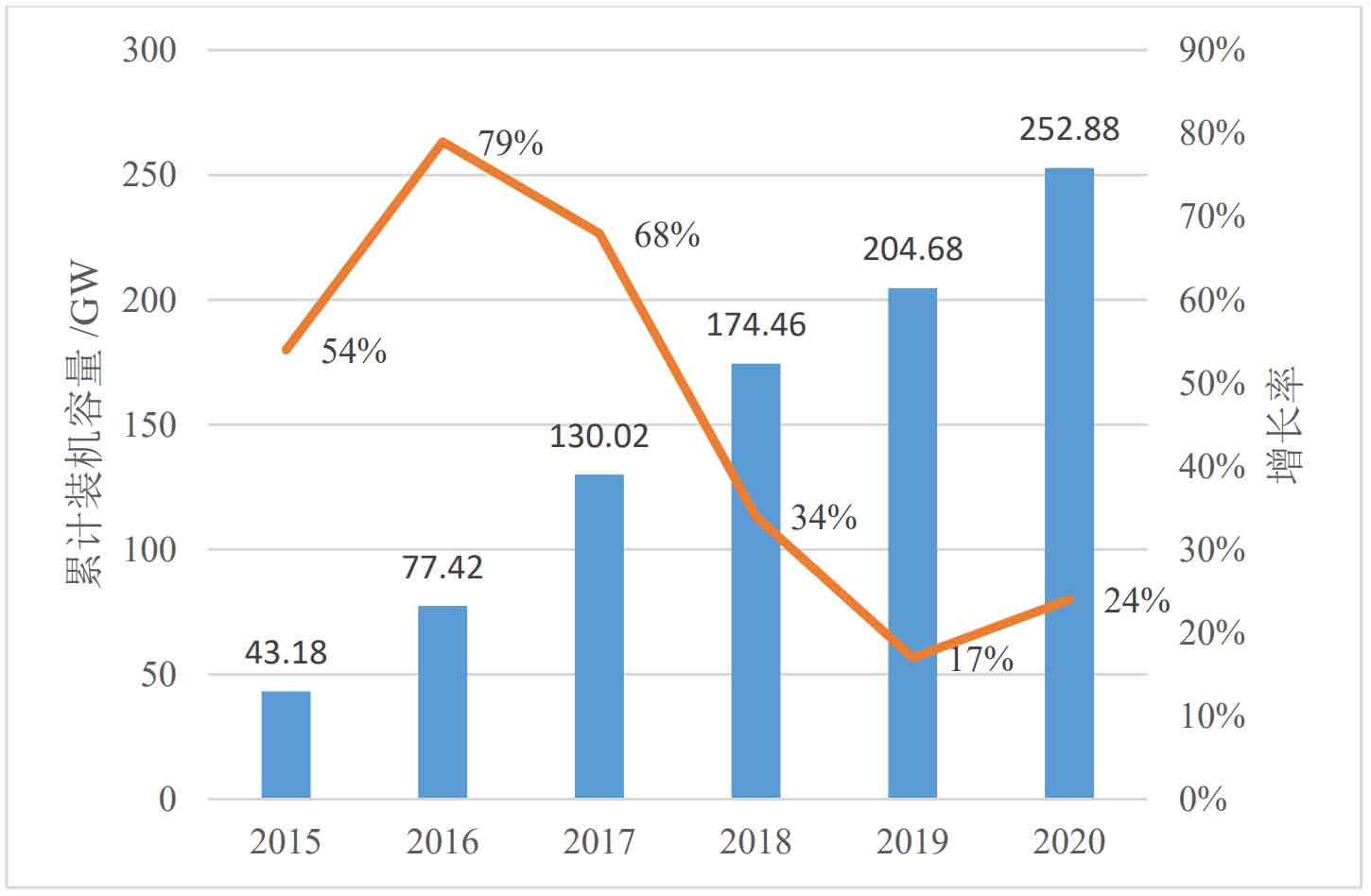
Figure 1 shows the cumulative installed capacity and growth rate of photovoltaic power generation in China from 2015 to 2020. It can be seen that the total installed capacity of photovoltaic power has been increasing year by year, but the growth rate has decreased compared to 2016 and 2017. With the increase of photovoltaic volume and national policy support, photovoltaic power generation systems will still have a broad market and higher research and development value in the future for a long time.
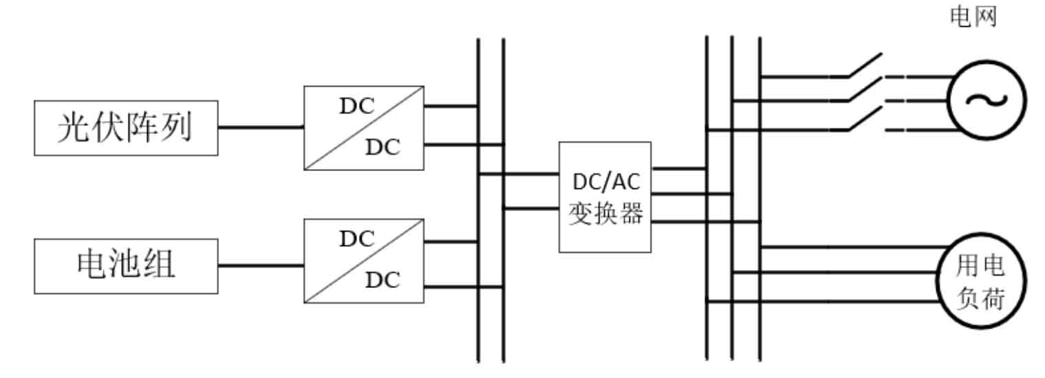
Figure 2 shows the principle and structure of a photovoltaic energy storage and generation system, where the photovoltaic array transmits energy to the DC power grid through a unidirectional DC to DC converter, and then transmits the energy to the AC bus through a DC to AC inverter to meet the electricity demand of the power grid and load; The energy storage battery pack transmits electrical energy to each other through a bidirectional DC DC converter and a DC bus, and then transmits power energy to the external AC power grid through an inverter.
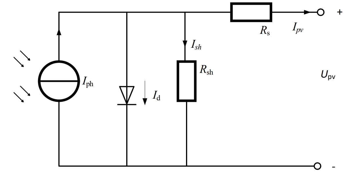
In the entire grid connected power generation system, photovoltaic cells play an important role as energy output units. The working principle of photovoltaic cells is that under lighting conditions, the internal charge state of photovoltaic cells changes, resulting in a potential difference. The equivalent circuit model is shown in Figure 3. Mainly including the ideal current source pH I, resistors Rs, Rsh, and diode VD. Assuming that the arrow in Figure 2 points in the direction of point voltage and positive current, according to Kirchhoff’s law, the I-U equation can be obtained as follows.
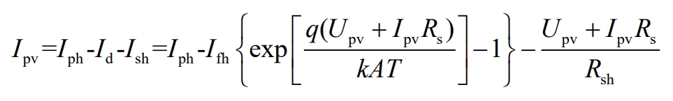
Where pv I is the output current of the battery; PH I refers to the current generated by light, and its magnitude is directly proportional to the intensity of light; DI is the current flowing through VD; Fh I is the reverse saturation current under no light conditions; K is the Boltzmann constant (k=1.38×10 ^ -23 j/K); A is the ideal factor of diode VD; T is the absolute temperature of the photovoltaic cell; Rsh is the parallel equivalent resistance of the photovoltaic cell; Rs is the equivalent resistance of the battery in series; Upv is the battery output voltage.
The relationship between the output voltage and output current of the photovoltaic cell array is shown in Equation 2.
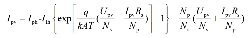
Among them, Ns and Np represent the number of cells connected in series and the number of cells connected in parallel with the photovoltaic array, respectively.
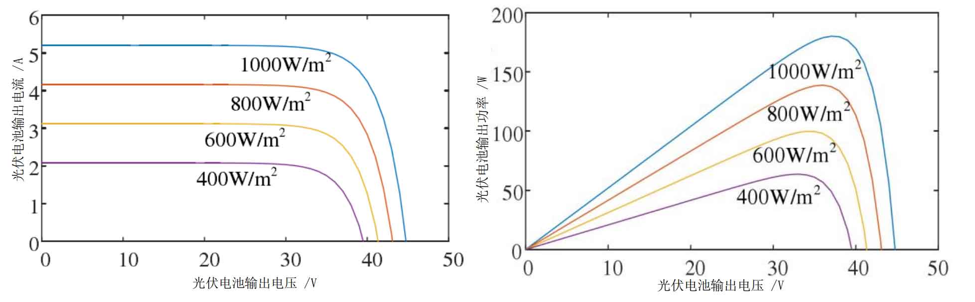
According to the photovoltaic mathematical model, the output current of the photovoltaic array is related to two factors: light intensity and temperature. Figures 4 and 5 show the output characteristic curves of photovoltaic cells under different conditions. Figure 4 shows the output characteristic curves of photovoltaic cells under different light intensities (at room temperature of 25 ℃). It can be seen that under the condition of constant light intensity, as the photovoltaic output voltage increases, the photovoltaic output current first remains unchanged and then decreases. The critical voltage is around 35V, and the greater the light intensity, the greater the photovoltaic output current; When the light intensity is constant, the photovoltaic output power first increases and then decreases with the change of output voltage. The critical voltage value is around 35V, and the greater the light intensity, the higher the photovoltaic output power.
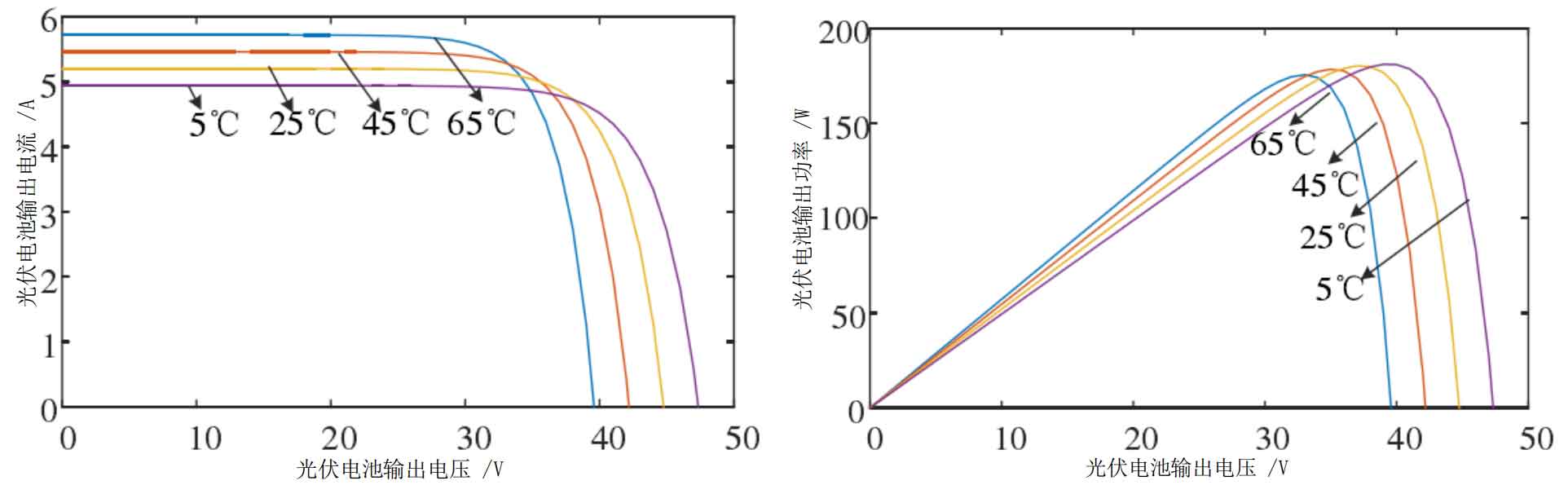
Figure 5 shows the effect of temperature on the output characteristic curve of photovoltaic cells under a constant light intensity (1000W/m2). When the initial photovoltaic output voltage is low, temperature has almost no effect on the output current of the photovoltaic power plant. As the voltage increases, the output current of the photovoltaic cell decreases significantly when it reaches the critical value of around 40V; The relationship between the output voltage and output power of photovoltaic cells is that the output power first increases and then decreases with the increase of output voltage. The critical point is around 35V, and the lower the temperature, the greater the critical point voltage value.
2.Energy storage technology and classification
Energy storage technology can be divided into many categories based on different standards, and can be classified according to different charging and discharging durations. It can be divided into three categories: power type (≤ 30min), energy type (1-2h), and capacity type (≥ 4h). The power type energy storage method has the fastest response speed, usually ranging from milliseconds to seconds, and its continuous energy storage duration is about 15-30 minutes. This type of energy storage is generally used in scenarios such as frequency modulation or smoothing fluctuations in new energy generation. Under this condition, power based energy storage technology is required to achieve instantaneous charging and discharging, and to achieve fast power support. Power based energy storage technology includes supercapacitors, flywheel energy storage, superconducting magnetic energy storage, and short-term energy storage power batteries such as ternary lithium batteries and lithium titanate batteries.
| Energy storage technology | Advantages | Disadvantages | Application direction |
| Pumped storage energy | Large capacity, low cost | High site requirements and long construction cycle | Peak shaving and valley filling, frequency modulation and phase modulation, system backup, black start |
| Compressed air energy storage | Large capacity, low cost | High site requirements | Peak shaving and valley filling, frequency modulation and phase modulation, system backup, black start |
| Flywheel energy storage | Mature technology | Low energy density | Peak shaving, frequency modulation, power quality regulation, etc |
| Lead-acid battery | Low investment and fast construction | Low lifespan and environmental pollution | Power quality, reliability, frequency control, black start, UPS |
| Lithium battery | Large capacity, high density, and high efficiency | High cost | Various applications |
| Sodium sulfur battery | Large capacity, high density, and high efficiency | High cost and safety hazards | Various applications |
| Liquid flow battery | Large capacity and long lifespan | Low energy density | Power quality, reliability, frequency control, peak shaving and valley filling, energy management |
| Supercapacitor | Long lifespan and high efficiency | Low energy density | Power quality, stability of transmission and distribution systems |
| Superconducting electromagnetic energy storage | Large capacity | High cost | UPS, power quality, stability of transmission and distribution systems |
The continuous energy storage time of energy based energy storage technology is between power based energy storage and capacity based energy storage technology, requiring a continuous energy storage time of about 1-2 hours. The scenario is generally a composite energy storage configuration, and the energy storage technology in this scenario is mainly used for grid peak shaving and auxiliary services, and is generally used for independent energy storage power plants on the grid side.
Capacity based energy storage technology continuously stores energy for more than 4 hours and is mainly used for energy storage systems on the power generation side. It is suitable for reducing peak valley differences in the main grid, relying on long-term charging and discharging to balance grid fluctuations and increase grid operation stability. Pumped storage power stations, all vanadium flow batteries, sodium sulfur batteries, lead carbon batteries, and other types of energy storage technologies are all capacity based. Table 1 shows a comparison of various current energy storage technologies, and Figure 2 shows the applicable ranges of different types of batteries.
Energy storage technology can be classified according to not only the duration of charging and discharging, but also the type of energy storage.
Pumped storage power stations are the only type of energy storage system that can profit from the electricity market mechanism among all current energy storage systems. The full life cycle of pumped storage power stations can reach 40 years, and their capacity can also reach the gigawatt level. Therefore, the best use of this type of energy storage power station is to cut peak and fill valley loads. However, due to the height difference and water source requirements of its construction site, as well as the harsh civil engineering conditions, it is destined that pumped storage power stations cannot be promoted on a large scale.
Electromagnetic energy storage is a type of power type energy storage, which has the advantage of extremely fast response speed, being able to respond to actions within millisecond time limits, and having an extremely long lifespan. It can be reused for tens of thousands of times in overcharge and discharge scenarios; The disadvantage is that the cost is too high and it is difficult to achieve profitability within the lifespan under current energy storage market policies.
Lithium batteries are the most commonly used type of energy storage batteries in large-scale energy storage stations, with excellent energy conversion efficiency and thousands of cycles of charging and discharging life, as well as extremely fast response speed and cycle charging and discharging life.
3.Energy storage system modeling
3.1 Structure of battery energy storage system
The typical structural diagram of a battery energy storage system is shown in Figure 6, where each battery module is composed of individual batteries in series and parallel, and the battery pack forms a battery system through parallel connection. A complete energy storage system includes energy storage subunits, DC converters, local monitoring modules, DC/AC converters, step-up transformers, energy monitoring and management systems, etc. The solid line represents the energy transmission path, and the dashed line represents the signal transmission path.
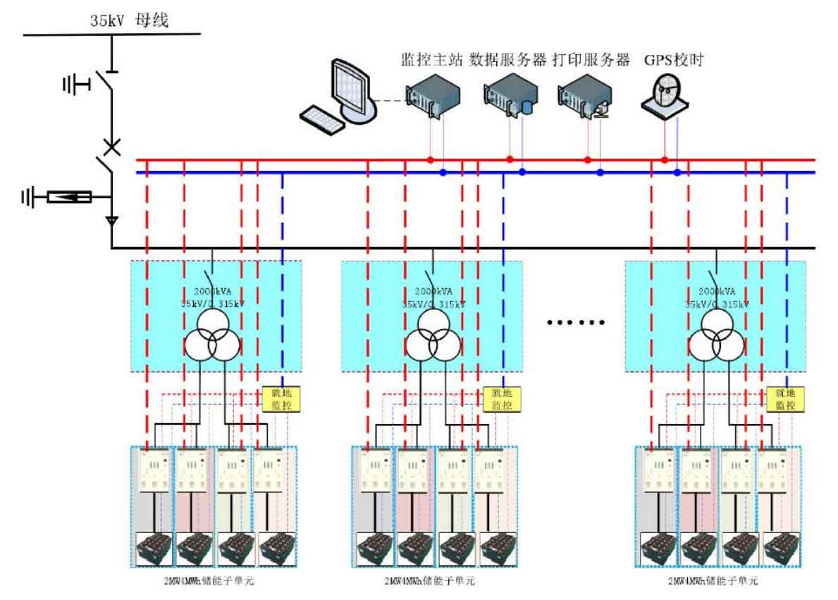
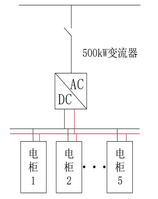
Taking a 1MW/2MWh lithium-ion battery system as an example, the integration scheme is as follows: each 1MW/2MWh energy storage unit consists of two 500kW/1MWh subunits, a total of 10 200kWh electrical cabinets, 2 combiner cabinets, 2 control cabinets, 2 energy storage converters (PCS) with a rated power of 500kW, and 1 monitoring cabinet. The structure of a single 500kW/1MWh subunit is shown in Figure 7.
The technical indicators of the energy storage subunit are shown in Table 2, where the parameters of the total energy on the DC side, rated voltage on the DC side, and working voltage on the DC side are all based on a room temperature of 25 ℃.
| Serial number | Project | Parameter |
| 1 | Total energy on DC side/MW | 2 |
| 2 | Rated voltage on DC side/V | 716.8 |
| 3 | DC side working voltage/ | 627.2~817.6 |
| 4 | Rated charging/discharging power/MW | 1/1 |
| 5 | Working temperature/℃ | Charging 0~55 ℃; Discharge -20~55 ℃ |
The structure of energy storage systems can be divided into two types: centralized and decentralized. The energy storage devices in centralized energy storage systems are arranged in a centralized manner to uniformly control the charging and discharging of battery packs, achieving multifunctional applications of energy storage in power systems.
For centralized large-scale wind farms or photovoltaic power plants, the functions of energy storage systems configured on the grid side can generally be classified into the following two categories
1) Smooth output: Utilizing the characteristics of rapid charging and discharging of active and reactive power in energy storage power stations, smooth the grid connected output curve and voltage fluctuations of new energy generation, improve the balance level of active and reactive power in the main grid system, and enhance stability.
2) Economic scheduling: By utilizing the fast charging and discharging characteristics of energy storage systems, the scheduling of renewable energy can be improved, thereby reducing costs.
Compared with centralized energy storage systems, decentralized energy storage systems reduce investment pressure and line losses in centralized power plants, and have the disadvantages of poor controllability and dispersed locations. The energy storage devices in its system are distributed across various units, mainly applied on the user side, distribution network side, and distributed power supply side. Nowadays, electric vehicles are also an important component. The distributed energy storage mode can be configured separately for different functional requirements, and energy storage can be managed separately, which can be applied under different functions.
The configuration of decentralized energy storage is more flexible compared to the control of centralized energy storage systems, and does not require large-scale series and parallel design of battery packs. This reduces the requirement for battery consistency, thereby reducing the design difficulty of energy storage systems. However, due to the independent operation of decentralized energy storage systems, it is not conducive to the collective scheduling and economic capacity allocation of large-scale energy storage systems.
3.2 Modeling of large-scale energy storage systems
The fast charging and discharging characteristics of the energy storage system make it have dual characteristics of power and load, which can serve as a power source and supply energy to the load when the power supply pressure is high in the power grid; It can also serve as a load, consuming excess electricity from the power grid and new energy generation through charging. State of Charge (SOC), as an important indicator to describe the remaining electricity level of energy storage systems, can be expressed as:
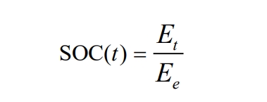
In the formula, Et represents the remaining capacity of the energy storage system at time t, and Ee represents the rated capacity of the system. During the charging and discharging process of the energy storage system, the SOC of the energy storage system is recursively calculated as follows:
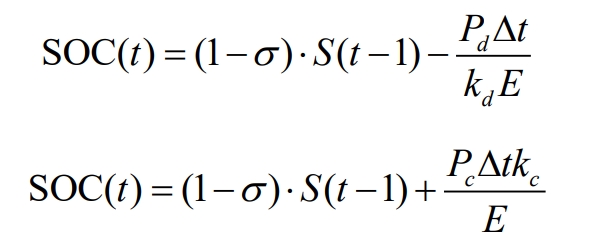
Among them, σ The self discharge rate of the system, which represents the indicator of the energy retention rate of the energy storage system. The larger the value, the greater the self loss of the energy storage equipment; SOC (t) represents the remaining power level of the energy storage device at time t. Kc and kd are their charging and discharging efficiency, respectively.
Overcharging and discharging of energy storage batteries can cause the internal voltage of the battery to be too high or too low. Overcharging can lead to an increase in temperature, deformation, and expansion of lithium-ion batteries; Excessive discharge can cause layered collapse of the negative electrode plate, leading to a decrease in capacity, an increase in internal resistance, and a shortened lifespan. In order to ensure the good operating status and lifespan of the battery, the SOC of the energy storage system needs to change within the normal range. The charging and discharging power of the dissolution energy storage system should meet the normal operating conditions of the system, namely:
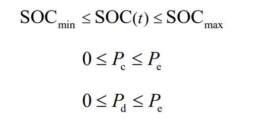
In actual working conditions, the value of SOCmin is between 20% and 30%, the value of SOCmax is around 80%, Pc and Pd are the charging and discharging power of the energy storage equipment, and Pe is the rated power of the energy storage equipment.
3.3 Economic Model of Large Scale Energy Storage System
The benefits of energy storage power stations can be divided into many types, including delaying equipment installation, promoting new energy access, peak shaving and frequency regulation, reducing user electricity bills through time-of-use electricity prices or implementing storefronts. According to the beneficiaries, they can be divided into three categories: power generation side, grid side, and user side, as shown in Table 3. For the power supply side, energy storage power stations can delay the corresponding capacity of power generation installation and improve the access capacity of renewable energy in the grid, It can be used as a black start power source within the power grid, which can quickly restore power supply to the power grid and power plants in the event of a large-scale accident power outage. For the user side, energy storage power stations can make the system more stable and ensure the reliability of power supply for important load units. On the other hand, they can also directly save electricity bills through time-of-use electricity prices through energy storage peak shaving and valley filling. The power grid side is currently the most direct manifestation of the economic benefits of battery energy storage stations, mainly including delaying distribution upgrading and renovation, peak shaving and frequency regulation, reducing line losses, load tracking, and providing rotating backup.
| Beneficiaries | Function | Benefit classification |
| Power supply side | Delaying power generation installation and promoting renewable energy access | Economic benefits |
| Power supply side | Ensure the operation of independent power grids and microgrids | Operational benefits |
| Grid side | Delaying power distribution upgrades and reducing line losses | Economic benefits |
| Grid side | Peak shaving, frequency modulation, provision of rotating backup | Operational benefits |
| Grid side | Load tracking | Social benefits |
| User side | Ensure user power supply | Economic benefits |
| User side | Save time of use electricity price and user electricity bills | Economic benefits |
The research on the economic benefits of battery energy storage power station technology has been widely concerned both domestically and internationally, but this project lacks a unified standardized quantitative evaluation method. Academician Yang Yusheng of the Chinese Academy of Chemical Defense proposed in reference [59] the use of the Economic Benefit Index (YCC) as a criterion for the economic benefits of large-scale energy storage devices, providing the calculation formula for YCC and the basis for judging economic benefits.
(1) Energy storage stations slow down the economic benefits of power grid construction
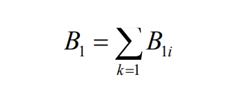
In the formula, B1 represents the economic benefits of slowing down the construction of the power grid after connecting to the energy storage device; B1i refers to the cost of constructing less or delayed substations and lines.
(2) Economic benefits of reducing line loss conversion
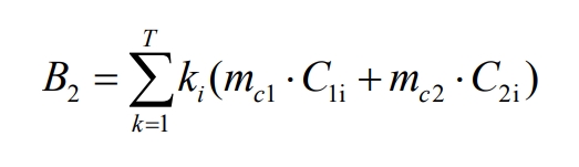
In the above equation, B2 represents the economic benefit of reducing line loss; C1i and C2i respectively represent the reduced carbon source emissions and total carbon emissions in the i-th year; Mc1 and mc2 represent the standard carbon cost per unit and the governance cost per unit of carbon emissions; Ki is the annual coefficient of the i-th year; R is the annual interest rate of the energy storage system.
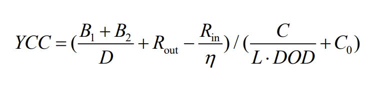
In summary, the economic benefits of energy storage power stations on the grid side can be converted from the above two economic benefits, and their benefit index can be expressed as:
4.Summary
Analyzed the composition of large-scale photovoltaic energy storage stations, and built a photovoltaic power station model, as well as a structural model and economic evaluation model for large-scale battery energy storage systems on the grid side. Considering the unified scheduling attribute of large-scale battery energy storage stations, a centralized energy storage system structure was selected as the scenario to provide a theoretical basis for subsequent capacity optimization configuration and active power optimization strategies.