
According to GB/T 10250 “Electromagnetic Compatibility of Electrical and Electronic Equipment in Ships” and GD01-2006 “Guidelines for Type Approval Testing of Electrical and Electronic Products” formulated by China Classification Society (CCS), static discharge immunity (ESD), radio frequency electromagnetic field immunity (RS), conducted disturbance immunity (CS) tests shall be conducted on the solar inverter control system of solar powered ships Electrical fast transient pulse group immunity test (EFT) and surge (impulse) immunity test SURGE and other indicator tests.
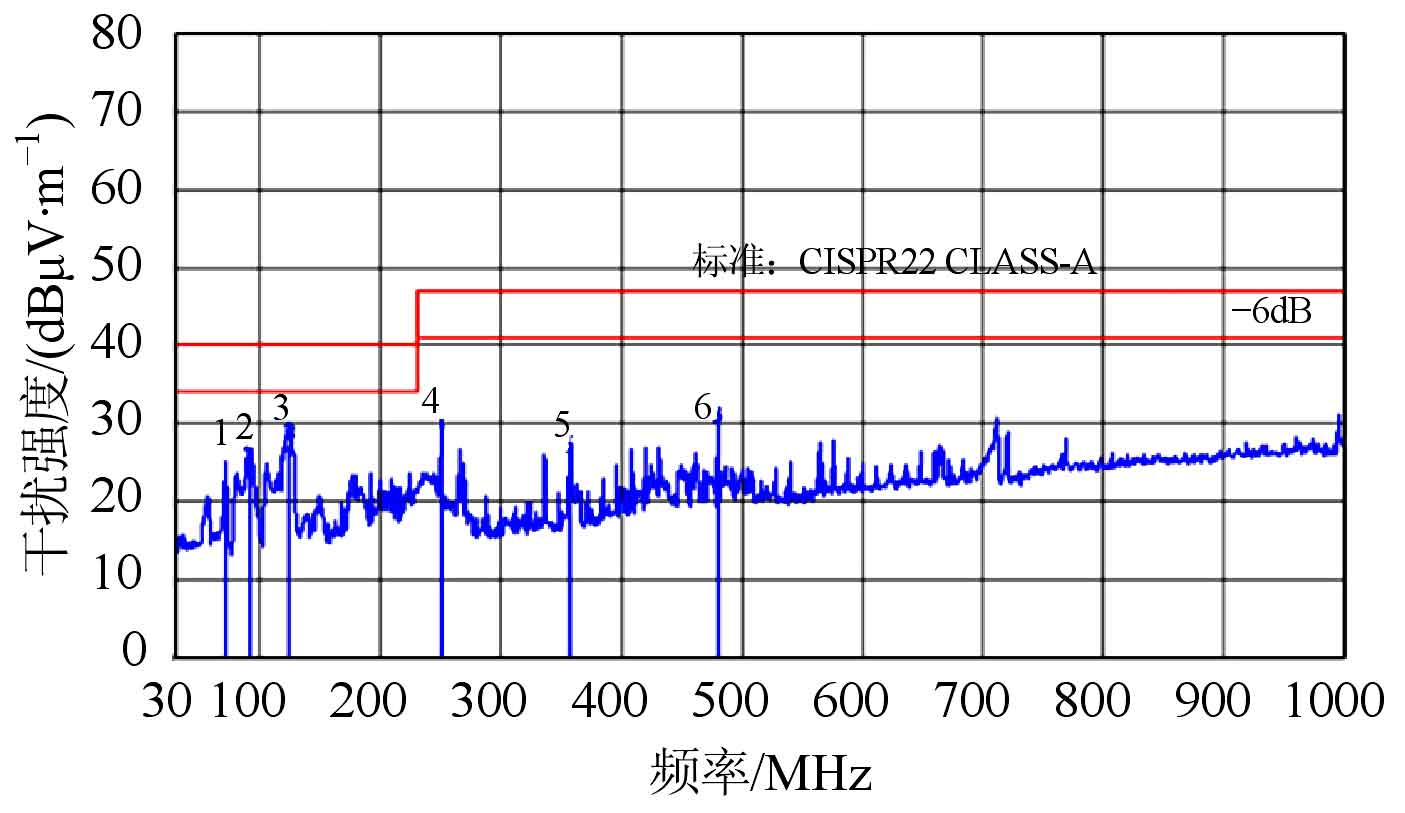
| Number | Frequency/MHz | Correction factor/(d B · m ^ -1) | Raw data/(d B) μ V · m ^ -1) | Radiation level/(d B) μ V · m ^ -1) | Strength limit/(d B) μ V · m ^ -1) | Strength margin/d B | Antenna height/cm | Angle of experimental table/(°) |
| 1 | 72.00 | 12.74 | 11.30 | 21.04 | 40.00 | -15.96 | 235 | 263 |
| 2 | 91.11 | 9.44 | 16.46 | 25.90 | 40.00 | -14.10 | 263 | 66 |
| 3 | 124.09 | 14.05 | 13.07 | 27.12 | 40.00 | -12.88 | 366 | 155 |
| 4 | 250.00 | 14.67 | 13.59 | 28.26 | 47.00 | -18.74 | 236 | 251 |
| 5 | 356.89 | 18.23 | 7.51 | 25.74 | 47.00 | -21.26 | 236 | 155 |
| 3 | 480.00 | 21.61 | 7.76 | 29.37 | 47.00 | -17.63 | 400 | 158 |
According to the testing principle, test indicators such as ESD, RS, CS, EFT, and SURGE. The data test results of RF electromagnetic field immunity test RS are shown in the table and figure. The results show that the indicators meet the requirements of the demonstration, while other test results have also passed the demonstration by authoritative EMC certification institutions.
Analyze the EMC test data and summarize the EMC indicators of the ship’s solar inverter control system as follows:
1) Antistatic ability: Contact discharge 4 kV, air discharge 8 kV;
2) Resistance to EFT interference: 2 kV between lines and 2 kV between lines and ground;
3) Anti surge interference capability: 1 kV between lines and 2 kV between lines and ground;
4) Anti radiation interference ability: A level demonstrated through CE certification;
5) Resistance to conducted interference: A level demonstrated through CE certification.
The experimental results show that the EMC design of the ship’s solar inverter control system has passed the EMC standard demonstration and meets the national reliability requirements for marine equipment. In the actual engineering process, sufficient attention should be paid to grounding, cable shielding, and layout and wiring processes to further improve the high reliability of control systems applied on ships.
With the continuous maturity and development of photovoltaic power generation technology, the application and promotion of photovoltaic power generation systems on ships is imperative. The requirements for the working environment and conditions of ship solar inverters are quite strict, and the requirements for the EMC design of the control system are also very high. In addition to using high reliability components, it is necessary to rationalize the internal and external EMC design. Through EMC testing, simulate the application environment on board the ship and conduct interference path analysis, adjust and optimize EMC design, propose design requirements for the design process and usage process, in order to achieve high reliability of the EMC capability of the ship’s solar inverter control system, and provide engineering practical EMC design ideas and experience for research designers.