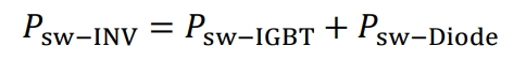
In the working scenarios of PWM solar inverters and other switching power supplies, the proportion of switching losses is relatively high. The switching loss mainly includes the switching loss of IGBT and the switching loss of diode. The turn-on loss of diode can generally be ignored, so the switching loss of diode is equal to its reverse recovery loss. The IGBT manufacturer provides the switch energy consumption Ets at rated voltage and current in the data manual, which includes the turn-on energy consumption Eon, turn-off energy consumption Eoff, and reverse recovery energy consumption ED rec of the IGBT’s anti parallel diode. The switching loss of IGBT is related to its switching frequency, conduction current, turn off voltage, and gate resistance. In actual circuits, the switching loss of IGBT can be estimated as:
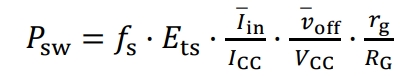
Fs is the switching frequency; ICC is the rated current given in the data manual; VCC is the rated turn off voltage; RG is the rated gate resistance value; Iin is the average current of the actual circuit; voff is the average turn off voltage in the actual circuit; RG is the gate resistance value in the actual circuit.
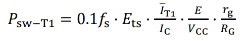
Due to T1 being a soft switch, its ideal switching loss is 0. Considering the small amount of loss generated by reactive power conversion during the switching process, the loss of the soft switch can be estimated to be 10% of the loss of the hard switch. The turn off voltage of T1 is a single DC power supply voltage, and its switching loss is:
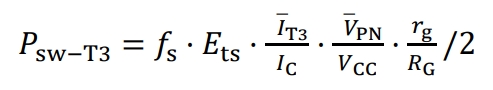
The switching losses of T3 and T4 are equal, and they only operate for half a cycle in one fundamental cycle. The switching losses of T3 are:
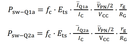
In the later stage inverter circuit, the IGBT switching losses of each phase bridge arm are equal. The IGBT switching losses of the A-phase bridge arm can be calculated first. The four IGBTs of the A-phase bridge arm only switch once in a fundamental cycle, and the switching losses of Q1a and Q4a are equal. The switching losses of Q2a and Q3a are equal, and their average turning off voltage is half of the bus voltage.
In actual circuits, the switching losses of Q1a and Q2a are smaller than the calculated values above, because the voltage before and after switching is close to 0. Therefore, the total IGBT switching losses of the two-stage solar inverter can be expressed as:
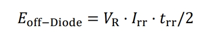
Regarding the turn off loss of diodes, the rated reverse recovery energy consumption can be calculated based on the manufacturer’s provided data manual:

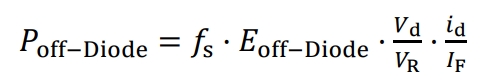
VR is the rated reverse bias voltage of the diode, Irr is the peak reverse recovery current of the diode under rated voltage and current conditions, and trr is the reverse recovery time. Therefore, the turnoff loss of the diode is:
IF is the rated conduction current of the diode, Vd is the actual reverse bias voltage of the diode, id is the actual conduction current of the diode, and the data manual of individual models of diodes will directly provide their turn off energy consumption.
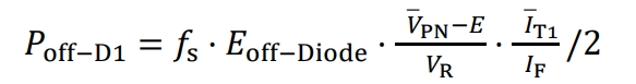
The switching losses of D1 and D2 diodes in the front-end circuit are equal, which can be expressed as:
The switching losses of diodes D3 and D4 are equal, and they only operate for half a cycle in one fundamental cycle. The diode turn off loss is:

The later stage inverter circuit has a total of 6 clamping diodes with equal turn off losses. Each diode effectively switches twice within a fundamental cycle, and the turn off loss of D5a can be calculated first:
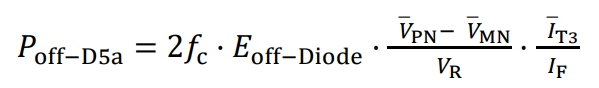
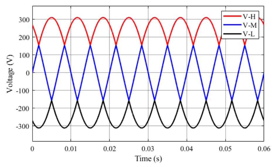
The cut-off voltage of D5a is the difference between the bus voltage and the midpoint voltage during T3 operation. Based on the symmetry of the graph, the average value of the midpoint voltage from 0 to π/3 can be calculated:

Total diode turn off loss of two-stage solar inverter:

Total switching loss of two-stage solar inverters: