
The pursuit of carbon neutrality has propelled the rapid development and widespread adoption of li ion battery technology. As a critical component in modern energy storage systems, li ion batteries power everything from consumer electronics to electric vehicles and large-scale grid storage. Within the architecture of a li ion battery, the current collector serves a vital, dual role: it acts as a mechanical support for the active electrode materials and provides the essential conductive pathway for electron transfer during charge and discharge cycles. Traditionally, metallic foils, primarily copper (Cu) for the anode and aluminum (Al) for the cathode, have fulfilled this function. However, these metallic foils constitute a significant portion of the battery’s non-active mass, typically accounting for 15-20% of the total weight, which inherently limits the overall energy density of the li ion battery.
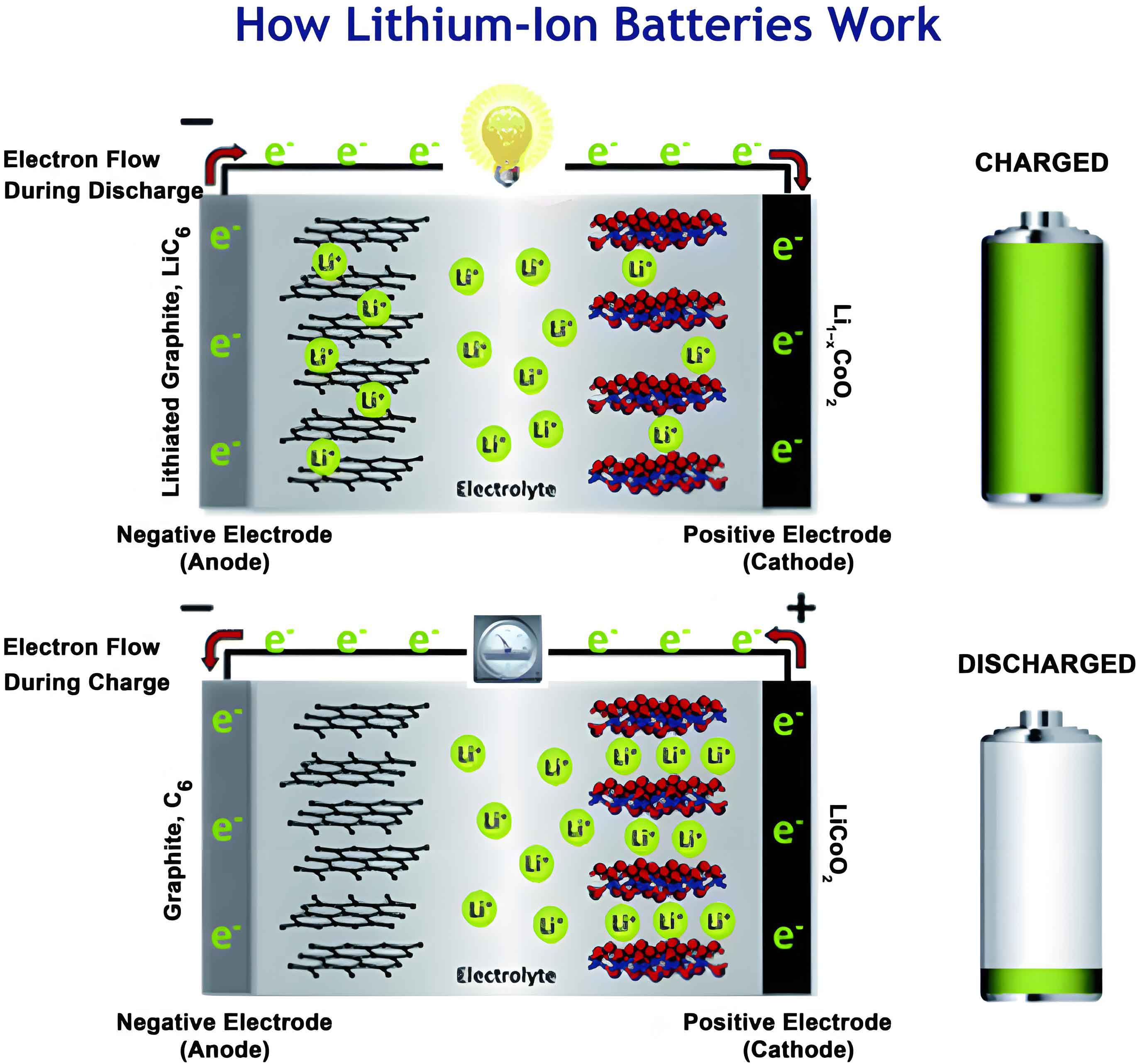
To address this limitation and push the boundaries of li ion battery performance, significant research efforts are directed towards lightweighting the current collector. Among the promising strategies, the development of polymer-based composite current collectors has garnered considerable industrial and academic interest. These composites typically feature a “sandwich” structure with a thin polymer film, such as polyethylene terephthalate (PET), as the central substrate, coated on both sides with conductive metal layers, usually copper. This design offers a compelling suite of advantages for next-generation li ion batteries: a substantial reduction in weight to enhance gravimetric energy density, improved safety characteristics by potentially mitigating thermal runaway, and the possibility of lower manufacturing costs. As the industry accelerates towards the commercialization and mass production of these materials, a thorough and systematic understanding of their mechanical properties becomes paramount for ensuring reliable performance and safe integration into li ion battery cells.
The manufacturing process of a li ion battery electrode subjects the current collector to various mechanical stresses, including coating, calendering, and winding. Furthermore, during electrochemical cycling, the active materials experience volume changes, inducing additional stress on the collector. Therefore, robust mechanical stability and predictable tensile properties are non-negotiable requirements. While extensive research exists on the mechanical behavior of traditional metal foil collectors, investigating the factors influencing the tensile performance of polymer composite collectors remains an underexplored yet critical area. Moreover, the absence of standardized testing protocols specifically for these novel composites necessitates a detailed investigation to inform future standards. This study presents a comprehensive investigation into the tensile properties of a commercial PET-Cu composite current collector. By employing a combination of advanced experimental techniques, including Digital Image Correlation (DIC), and finite element simulation, we systematically deconstruct the influence of key testing parameters—specimen geometry, sampling direction, strain rate, and geometrical dimensions—on the measured mechanical response. The findings provide a fundamental mechanical reliability assessment and offer practical guidance for the evaluation and standardization of composite current collectors in li ion battery applications.
1. Experimental Methodology
1.1 Material and Microstructural Characterization
The material under investigation is a commercially available PET-Cu composite current collector designed for li ion battery applications. Its structure consists of a central PET polymer substrate with a nominal thickness of 4.9 μm, symmetrically coated on both sides with Cu layers, each approximately 1 μm thick, resulting in a total composite thickness of 6.9 μm. The manufacturing process involves depositing a thin conductive seed layer via magnetron sputtering onto the PET film, followed by electrochemical deposition to build up the functional Cu coating to the desired thickness. For comparative analysis, the bare PET substrate (4.9 μm thick) and a conventional rolled Cu foil (6 μm thick) used in standard li ion batteries were also evaluated.
The surface morphology and microstructure of the composite were characterized using Field Emission Scanning Electron Microscopy (FE-SEM). Surface roughness parameters (Ra, Sa) were quantified using Laser Scanning Confocal Microscopy (LSCM) over multiple 259 μm × 259 μm areas. The crystallographic texture of the Cu layers was determined by X-ray Diffraction (XRD) with Cu-Kα radiation. Key microstructural features such as void density, average void size, and Cu grain size were statistically analyzed from SEM images.
1.2 Tensile Testing Protocol
Tensile specimens were precisely machined using a femtosecond laser cutter to ensure clean, burr-free edges. Two primary specimen shapes were investigated: a dog-bone shape and a rectangular strip. The dog-bone specimen, with its tapered gauge section, is designed to promote failure within the central region and minimize stress concentrations at the grips. Testing was conducted on a micro-mechanical testing system under displacement control.
A critical aspect of testing thin, compliant materials like composite collectors is accurate strain measurement. The conventional method of calculating strain from crosshead displacement includes extraneous deformations from the machine compliance and specimen slippage at the grips, leading to significant overestimation of ductility. To obtain true material strain, non-contact Digital Image Correlation (DIC) was employed. This technique tracks the displacement of a speckle pattern applied to the specimen gauge length, providing full-field, high-fidelity strain data. The stress data was acquired directly from the load cell. The experimental matrix was designed to isolate the effects of various parameters, as summarized in Table 1.
| Influencing Factor | Specimen Shape | Sampling Direction | Strain Rate (s-1) | Gauge Length (mm) | Gauge Width (mm) |
|---|---|---|---|---|---|
| Specimen Shape | Dog-bone, Rectangle | Machine Direction (MD) | 1 × 10⁻³ | 50 | 10 |
| Sampling Direction | Dog-bone | MD, Transverse Direction (TD) | 1 × 10⁻³ | 50 | 10 |
| Strain Rate | Dog-bone | MD | 5 × 10⁻⁴, 1 × 10⁻³, 5 × 10⁻³ | 50 | 10 |
| Gauge Width | Dog-bone | MD | 1 × 10⁻³ | 50 | 5, 10, 15, 25 |
| Gauge Length | Dog-bone | MD | 1 × 10⁻³ | 25, 50, 75, 100 | 10 |
1.3 Finite Element Simulation
To complement the experimental work and visualize stress distributions, two-dimensional plane stress finite element models were constructed for both dog-bone and rectangular specimen geometries using commercial software (Abaqus). The composite was modeled as a homogeneous orthotropic material. Based on initial tensile data, a Young’s modulus of 28 GPa and a Poisson’s ratio of 0.3 were assigned. The models were meshed with fine quadratic elements, and a uniform tensile displacement was applied to simulate the loading condition. The simulation aimed to compare the stress homogeneity and concentration factors between the two specimen shapes.
2. Results and Discussion
2.1 Microstructural Characteristics of the Composite
The surface of the PET-Cu composite current collector exhibited a characteristic morphology from the electrochemical deposition process. Both top and bottom Cu surfaces appeared similar, featuring a population of irregularly shaped voids or defects. Statistical analysis revealed a void density of approximately 606 voids/mm2 with an average diameter of $$(1.84 \pm 0.87) \mu m$$. These voids are likely initiated at imperfections in the sputtered seed layer and propagated during the subsequent electroplating stage. The Cu coating itself consisted of relatively equiaxed grains with an average size of $$(2.84 \pm 1.00) \mu m$$, and the presence of annealing twins was frequently observed within the grains. XRD analysis confirmed a strong out-of-plane texture for the Cu layers, with dominant (111) and (200) diffraction peaks. Surface roughness measurements indicated very similar topography on both sides, with an arithmetic mean roughness (Ra) of about 0.058 μm. These microstructural features, particularly the voids, are expected to influence the mechanical performance and failure mechanisms of the composite in a li ion battery.
2.2 The Critical Role of Specimen Shape and Strain Correction
The choice of specimen geometry fundamentally affects the stress state and the location of failure. Finite element simulation clearly demonstrated this effect. Under tensile loading, the dog-bone specimen showed a gradual transition of stress from the gripped ends into the parallel gauge section, resulting in a uniform stress distribution within the gauge length. In contrast, the rectangular specimen exhibited a sharp stress concentration at the fillet where the gauge section meets the wider grip area. This concentration acts as a preferential site for failure initiation, often causing the specimen to rupture outside the intended gauge section, which compromises the accuracy of the measured strength and elongation.
Experimentally, this translated into distinct tensile curves. Rectangular specimens typically showed a shorter plastic deformation regime and lower apparent ductility compared to dog-bone specimens tested under identical conditions. Consequently, for reliable and reproducible evaluation of PET-Cu composite current collectors—and likely other thin-film materials for li ion batteries—the use of a dog-bone shaped specimen is strongly recommended. It ensures failure occurs within the gauge section, allowing for a valid measurement of the material’s intrinsic properties.
Furthermore, the method of strain calculation has a profound impact on the reported ductility. A direct comparison between strain values derived from crosshead displacement and those measured by DIC revealed a significant discrepancy. For instance, a specimen loaded in the machine direction (MD) showed an elongation at break of 18.5% from crosshead displacement, while the DIC-corrected value was only 12.5%. This overestimation, which can exceed 50%, arises from system compliance and grip slippage. Therefore, employing a non-contact strain measurement technique like DIC is not merely beneficial but essential for obtaining accurate mechanical property data for composite current collectors in li ion battery research and quality control.
2.3 Anisotropy: Influence of Sampling Direction
The PET-Cu composite exhibited clear anisotropic tensile behavior, meaning its properties depended on the direction relative to the original manufacturing roll direction. Specimens taken along the Machine Direction (MD) demonstrated superior mechanical performance compared to those taken along the Transverse Direction (TD). The tensile properties are summarized below:
| Sampling Direction | Yield Strength, $\sigma_y$ (MPa) | Ultimate Tensile Strength, $\sigma_{uts}$ (MPa) | Elongation at Break, $\epsilon_{te}$ (%) |
|---|---|---|---|
| Machine Direction (MD) | $$131.8 \pm 2.1$$ | $$201.5 \pm 1.3$$ | $$12.5 \pm 0.1$$ |
| Transverse Direction (TD) | $$122.8 \pm 2.1$$ | $$175.5 \pm 0.7$$ | $$8.8 \pm 0.3$$ |
While the electrodeposited Cu layer itself is largely isotropic in-plane, the anisotropy originates from the PET polymer substrate. During the film manufacturing process, polymer chains undergo orientation and alignment in the machine direction. This molecular orientation leads to stronger intermolecular forces and better load-bearing capacity when stressed along the MD, resulting in higher strength and ductility. This directional dependence is a crucial factor that must be specified in any mechanical characterization standard or material datasheet for composite current collectors used in li ion batteries.
2.4 Strain Rate Sensitivity of Mechanical Response
The tensile properties of the PET-Cu composite were found to be sensitive to the rate of loading, a characteristic known as strain rate sensitivity. This is a critical consideration for a li ion battery component that may experience varying load conditions during processing or in service. As the strain rate increased from $$5 \times 10^{-4} s^{-1}$$ to $$5 \times 10^{-3} s^{-1}$$, all key mechanical metrics showed a positive correlation. The results are detailed in Table 2.
| Strain Rate ($s^{-1}$) | Yield Strength, $\sigma_y$ (MPa) | Ultimate Tensile Strength, $\sigma_{uts}$ (MPa) | Elongation at Break, $\epsilon_{te}$ (%) |
|---|---|---|---|
| $$5 \times 10^{-4}$$ | $$126.1 \pm 2.0$$ | $$192.7 \pm 1.8$$ | $$10.9 \pm 0.8$$ |
| $$1 \times 10^{-3}$$ | $$131.8 \pm 2.1$$ | $$201.5 \pm 1.3$$ | $$12.5 \pm 0.2$$ |
| $$5 \times 10^{-3}$$ | $$137.1 \pm 1.7$$ | $$221.0 \pm 5.2$$ | $$13.9 \pm 0.6$$ |
This simultaneous increase in both strength and ductility with strain rate is a combined effect of the constitutive behaviors of both components in the composite. For the viscoelastic PET polymer, higher strain rates reduce the time available for molecular chain relaxation and rearrangement, leading to enhanced resistance to deformation (higher strength). For the metal coating, increased strain rates typically elevate the work hardening rate. The synergistic effect results in the observed positive strain rate sensitivity. This behavior underscores the importance of defining and controlling the strain rate during standardized testing of materials for li ion battery components to ensure consistent and comparable results.
2.5 Geometrical Size Effect on Ductility
A notable finding was the geometrical size effect, particularly on the ductility of the composite. While variations in gauge width (W) and gauge length (L) had a relatively minor influence on strength properties (changes within ~5%), they profoundly affected the measured elongation at break. Specifically, the elongation decreased significantly with increasing gauge length and increased with increasing gauge width. This phenomenon is related to the statistics of defect distribution and crack initiation. A longer gauge length presents a larger volume of material, increasing the probability of encountering a critical flaw (like a large void) that can initiate failure. Conversely, a narrower width localizes the damage from a propagating crack more effectively, reducing the overall ductility.
To model this effect, a geometrical size coefficient K was introduced, defined as:
$$K = \frac{L}{W \cdot t}$$
where \(t\) is the specimen thickness. The relationship between K and the elongation at break \(\epsilon_{te}\) can be described by a probabilistic model:
$$\epsilon_{te} = 1 + \frac{1}{\lambda_0} \left[ 1 – \exp\left(-\frac{K}{K_0}\right) \right]$$
where \(\lambda_0\) and \(K_0\) are material-fitting parameters. For the studied PET-Cu composite, the experimental data fitted this model well with \(\lambda_0 = 0.09\) and \(K_0 = 68\). This relationship provides a valuable tool for predicting the tensile ductility of the composite current collector for different specimen dimensions, which is crucial for correlating data obtained from different testing standards or for designing quality control tests for li ion battery materials.
2.6 Fracture Mechanism and Damage Analysis
Post-mortem SEM analysis of fractured tensile specimens revealed consistent damage features. The fracture surface region showed multiple cracks perpendicular to the loading direction. Closer inspection near these cracks revealed dense slip bands within the Cu grains, indicating that plastic deformation in the metal layer was primarily governed by dislocation slip. Crucially, the initiation sites for many of these cracks were often traced back to the pre-existing surface voids in the Cu coating. These voids act as stress concentrators under tensile load, promoting early crack nucleation and thus limiting the overall ductility of the composite. This highlights the importance of manufacturing process control to minimize such defects, as they directly impact the mechanical reliability of the current collector in a li ion battery.
2.7 Performance Benchmarking and Summary of Influencing Factors
To contextualize the performance of the PET-Cu composite, its tensile properties were compared with its constituent materials, as shown in Table 3. While the composite’s strength is lower than that of a standard Cu foil, its ductility is significantly higher, which can be beneficial for accommodating strains during electrode processing and cycling in a li ion battery.
| Material | Yield Strength (MPa) | Ultimate Tensile Strength (MPa) | Elongation at Break (%) |
|---|---|---|---|
| PET-Cu Composite | $$131.8 \pm 2.1$$ | $$201.5 \pm 1.3$$ | $$12.5 \pm 0.2$$ |
| PET Film | $$105.0 \pm 0.2$$ | $$288.9 \pm 11.8$$ | $$170.5 \pm 11.1$$ |
| Cu Foil | $$272.6 \pm 2.2$$ | $$301.9 \pm 0.4$$ | $$7.8 \pm 0.3$$ |
The comprehensive influence of the investigated factors on the tensile properties is synthesized below. Strain rate had the most pronounced effect on yield strength (Δ~11 MPa). Both strain rate and sampling direction significantly affected the ultimate tensile strength (Δ~28 MPa and ~26 MPa, respectively). Most strikingly, the method of strain measurement (correction) had the largest absolute impact on reported ductility (Δ~6%), followed by specimen dimensions and sampling direction. This analysis unequivocally demonstrates that the measured mechanical properties of a PET-Cu composite current collector are not intrinsic constants but are contingent upon the specific testing methodology employed.
3. Conclusion
This systematic study elucidates the tensile behavior of a commercial PET-Cu composite current collector and establishes the profound influence of testing methodology on its measured mechanical properties. The key conclusions for researchers and engineers working on advanced li ion battery components are as follows:
First, for reliable property evaluation, tensile testing should be conducted using dog-bone shaped specimens coupled with a non-contact strain measurement technique like DIC. This combination mitigates stress concentrations and prevents the gross overestimation of ductility associated with crosshead displacement calculations.
Second, the composite exhibits inherent anisotropy due to the molecular orientation of the PET substrate, leading to superior strength and ductility in the machine direction compared to the transverse direction. This anisotropy must be accounted for in material specification and cell design for li ion batteries.
Third, the material demonstrates positive strain rate sensitivity, with both strength and ductility increasing at higher loading rates. This viscoelastic-viscoplastic response necessitates the definition of a standard strain rate for comparative testing.
Fourth, a pronounced geometrical size effect exists, primarily affecting ductility. Elongation at break decreases with increasing gauge length and decreasing gauge width. This effect can be modeled using a geometrical coefficient K, providing a framework for correlating data from different specimen sizes.
Finally, the primary deformation mechanism in the Cu layer is dislocation slip, and pre-existing surface voids act as potent sites for crack initiation, ultimately limiting performance. This underscores the critical link between manufacturing quality control and the mechanical reliability of the composite in a li ion battery.
In summary, the successful integration of polymer composite current collectors into next-generation, high-performance li ion batteries hinges on a robust understanding of their mechanical behavior. The findings presented herein provide essential guidelines for the accurate characterization, standardization, and application-oriented design of these promising materials, contributing directly to the development of safer and more energy-dense li ion battery systems.