
In recent years, the rapid development of clean energy sources, such as photovoltaic and wind power, has driven the need for energy storage systems to stabilize grid fluctuations. Lithium-ion batteries, particularly LiFePO4 batteries, are widely used in energy storage stations due to their high energy density and long cycle life. However, safety concerns, especially thermal runaway caused by overcharging, remain a critical issue. Thermal runaway can lead to fires, explosions, and toxic gas emissions, posing significant risks in large-scale energy storage applications. Therefore, understanding the characteristic parameters during overcharge thermal failure is essential for developing effective early warning systems. In this study, we conducted a two-stage overcharge experiment on a 100 A·h LiFePO4 energy storage battery to investigate the behavior in the early stages of thermal failure. By monitoring characteristic gases, voltage, temperature, and other parameters, we analyzed the failure mechanisms and assessed the risk status after stopping overcharge. Our goal is to identify key indicators for early warning and provide insights into safe operation of LiFePO4 battery systems.
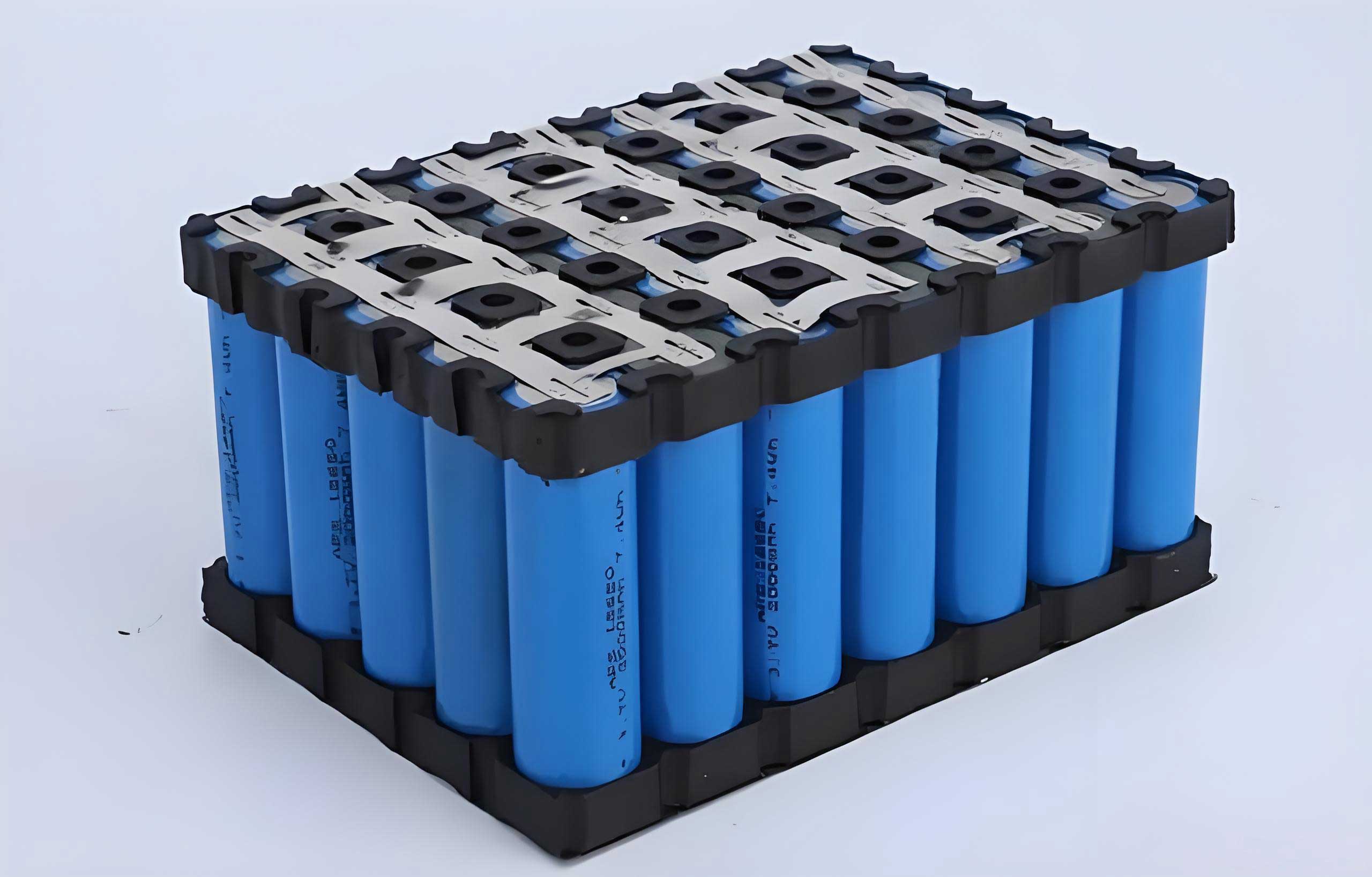
The experiment was performed using a 100 A·h single LiFePO4 battery with dimensions of 160 mm × 118.5 mm × 50 mm. The battery parameters are summarized in Table 1. The electrolyte primarily consisted of lithium salt LiPF6 and solvents including dimethyl carbonate (DMC), diethyl carbonate (DEC), ethyl methyl carbonate (EMC), and ethylene carbonate (EC). The overcharge and gas detection platform, as shown in the image below, comprised a battery testing system, an overcharge experimental chamber, temperature detectors, K-type thermocouples, gas detectors, and visible light monitoring equipment. The chamber was semi-enclosed with dimensions of 1400 mm × 700 mm × 700 mm. Additionally, a Thermo Scientific TRACE 1300 gas chromatograph (GC) was used to analyze gas composition. The battery testing system recorded voltage and current at a sampling frequency of 1 Hz. Gas detectors for H2, CO, CO2, and HF were employed with a resolution of 1×10⁻⁴% and a sampling frequency of 1 Hz. Alarm thresholds were set at 2×10⁻³ for H2 and CO, and 5×10⁻³ for CO2.
Prior to overcharge, the LiFePO4 battery was charged at 0.5C (50 A) to 3.65 V using constant current-constant voltage (CC-CV) method and left to rest for 2 hours until the surface temperature stabilized at 27°C. The overcharge experiment was divided into two stages:
- First-stage overcharge (early thermal failure): The battery was charged at 0.5C (50 A) constant current until the voltage reached 20 V, at which point charging was interrupted.
- Second-stage overcharge (thermal failure): After 30 minutes from the first stage, charging was resumed at 0.1C (10 A) constant current until internal short circuit and thermal failure occurred.
This two-stage approach allowed us to explore the effectiveness of warnings at a late stage (voltage reaching 20 V) and assess the battery’s safety after interruption. During the experiment, voltage, current, temperature, and gas emissions were monitored. Gas samples were collected at key time points using syringes and analyzed via GC. The experiment was repeated three times to ensure reproducibility.
The voltage and current profiles during overcharge are shown in Figure 1. In the first stage, the voltage increased rapidly to 4.38 V initially, followed by a slow rise to 5.06 V. At 835 s, the voltage peaked and began to decline. The safety valve opened at 1178 s when the voltage was 4.85 V, releasing smoke and brown electrolyte. After valve opening, the voltage rebounded and entered a second rapid rise phase, reaching 20 V at 1350 s with a rate up to 1.2 V/s. The overcharge capacity at this point was 15.7% state of charge (SOC). In the second stage, the voltage immediately rose rapidly from 5.69 V to 18.82 V in 220 s, then fluctuated before dropping to 0 V at 510 s due to internal short circuit. The charging capacity in this stage was only 1.5% SOC. This indicates that even after stopping overcharge at a late stage, the LiFePO4 battery remained at risk of thermal failure.
Temperature measurements on the battery surface revealed distinct trends. In the first stage, before safety valve opening, temperatures increased slowly at less than 0.05°C/s. At valve opening, the side temperature was highest at 59.1°C. After charging stopped at 1350 s, temperatures continued to rise for about 5 minutes before declining, with the negative terminal reaching 85.7°C. In the second stage, temperatures rose steadily until internal short circuit, after which rates exceeded 1°C/s, with the front surface peaking at 162.6°C. This suggests ongoing exothermic reactions even after charging cessation, particularly from lithium dendrite reactions.
Gas detection results are summarized in Table 2. Before safety valve opening, H2, CO, and CO2 levels were unchanged. Upon valve opening, H2 and CO increased simultaneously, with H2 reaching the alarm threshold in 5 seconds and CO in 13 seconds. CO2 levels rose gradually after 13 seconds. GC analysis showed that H2 was the earliest and most abundant gas, peaking at 7.44% volume fraction during thermal failure. CO followed, while hydrocarbon gases such as CH4, C2H6, C2H4, C3H8, and C4H10 were detected later. Among hydrocarbons, C2H4 dominated, accounting for 78.5% of total hydrocarbons at its peak. The gas evolution patterns align with chemical reactions during overcharge, as discussed below.
| Parameter | Value |
|---|---|
| Rated Capacity (A·h) | 100 |
| Operating Voltage (V) | 2.5–3.65 |
| Internal Resistance (1 kHz, mΩ) | 0.2–0.5 |
| Battery Mass (kg) | 2.0 |
| Stage | H2 (%) | CO (%) | CO2 (%) | CH4 (%) | C2H6 (%) | C2H4 (%) | C2H2 (%) | C3H8 (%) | C3H6 (%) | C4H10 (%) |
|---|---|---|---|---|---|---|---|---|---|---|
| Before Valve Open | 0 | 0 | 0.1112 | 0 | 0 | 0 | 0 | 0 | 0 | 0 |
| After Valve Open | 0.1724 | 0.0309 | 0.2426 | 0.0073 | 0.0034 | 0.0036 | 0 | 0.0002 | 0 | 0.0003 |
| Thermal Failure | 7.4424 | 1.3725 | 3.8260 | 0.5523 | 0.1182 | 0.6224 | 0.0041 | 0.0259 | 0.0025 | 0.0180 |
The gas generation mechanisms during overcharge of the LiFePO4 battery can be explained through chemical reactions. In the early stage, lithium dendrites form on the graphite anode due to over-lithiation, reacting with the binder polyvinylidene fluoride (PVDF) to produce H2:
$$ \text{CH}_2\text{CF}_2 + \text{Li} \rightarrow \text{CH}_2\text{CF}_2\text{Li} + \text{LiF} + \text{H}_2 $$
This reaction releases heat and causes voltage rise. As overcharge continues, lithium dendrites react with organic solvents in the electrolyte, generating gases like CO and hydrocarbons:
$$ 4\text{Li} + \text{C}_4\text{H}_8\text{O}_3 \text{(EMC)} \rightarrow \text{CH}_3\text{CHOCO}_2\text{Li} + \text{CH}_4 $$
$$ 2\text{Li} + \text{C}_3\text{H}_6\text{O}_3 \text{(DMC)} \rightarrow \text{Li}_2\text{CO}_3 + \text{C}_2\text{H}_6 $$
$$ 2\text{Li} + \text{C}_3\text{H}_4\text{O}_3 \text{(EC)} \rightarrow \text{Li}_2\text{CO}_3 + \text{C}_2\text{H}_4 $$
When temperature exceeds 90°C, the solid electrolyte interphase (SEI) decomposes, releasing C2H4 and CO2:
$$ (\text{CH}_2\text{OCO}_2\text{Li})_2 \rightarrow \text{Li}_2\text{CO}_3 + \text{C}_2\text{H}_4 + \text{CO}_2 + \frac{1}{2}\text{O}_2 $$
Positive electrode decomposition produces O2, which oxidizes electrolyte solvents to CO2 and H2O (or CO under O2 deficiency):
$$ \text{LiFePO}_4 \rightarrow \text{Fe}_2\text{P}_2\text{O}_7 + \frac{1}{2}\text{O}_2 $$
$$ \frac{5}{2}\text{O}_2 + \text{C}_3\text{H}_4\text{O}_3 \text{(EC)} \rightarrow 2\text{H}_2\text{O} + 3\text{CO}_2 $$
The high abundance of C2H4 is attributed to EC decomposition and SEI breakdown. After charging stops, residual lithium dendrites continue to react, sustaining temperature rise and gas emission. This explains why the LiFePO4 battery remains hazardous post-interruption.
The thermal failure patterns observed in this study offer insights for early warning systems. The voltage curve during overcharge shows four phases: rapid rise, slow rise, decline, and second rapid rise. For the 100 A·h LiFePO4 battery, the voltage reached 20 V before thermal failure, about 5.5 times the nominal voltage. This contrasts with smaller batteries where failure occurs at lower voltages, indicating capacity-dependent internal resistance. Thus, voltage thresholds for warning must be tailored to battery capacity. Gas analysis reveals that H2 is the earliest and most prominent indicator, suitable for primary warning. CO and hydrocarbons like C2H4 serve as secondary warnings. Temperature monitoring shows significant internal-external gradients (over 110°C), limiting the reliability of surface sensors. Therefore, a multi-parameter approach is recommended.
Based on our findings, we propose a hierarchical warning strategy for LiFePO4 battery overcharge thermal failure:
- Pre-valve opening: Use voltage warning during the first rapid rise phase (3.65–5.06 V).
- Post-valve opening: Implement H2 and CO as primary warnings, with hydrocarbons as secondary warnings.
- Second voltage rise phase: Set voltage at 4.85–20 V as a tertiary warning.
This strategy leverages the characteristic parameters of the LiFePO4 battery to enable timely intervention. Importantly, stopping overcharge during the second voltage rise phase can prevent thermal failure, but residual reactions may still pose risks, necessitating continuous monitoring.
In conclusion, our study on LiFePO4 battery overcharge thermal failure highlights key characteristic parameters for safety management. The two-stage experiment demonstrated that H2 is the most effective early warning gas, appearing at least 3 minutes before thermal failure. Voltage trends provide critical timing for intervention, with the second rapid rise phase being a viable cutoff point. However, post-interruption temperature rise indicates ongoing exothermic reactions, emphasizing the need for cautious handling. The proposed warning strategy integrates gas, voltage, and temperature data to enhance the safety of LiFePO4 battery energy storage systems. Future work should explore real-time sensor integration and adaptive thresholds for diverse battery configurations. Ultimately, understanding these parameters is vital for mitigating risks and promoting the sustainable use of LiFePO4 batteries in energy storage applications.