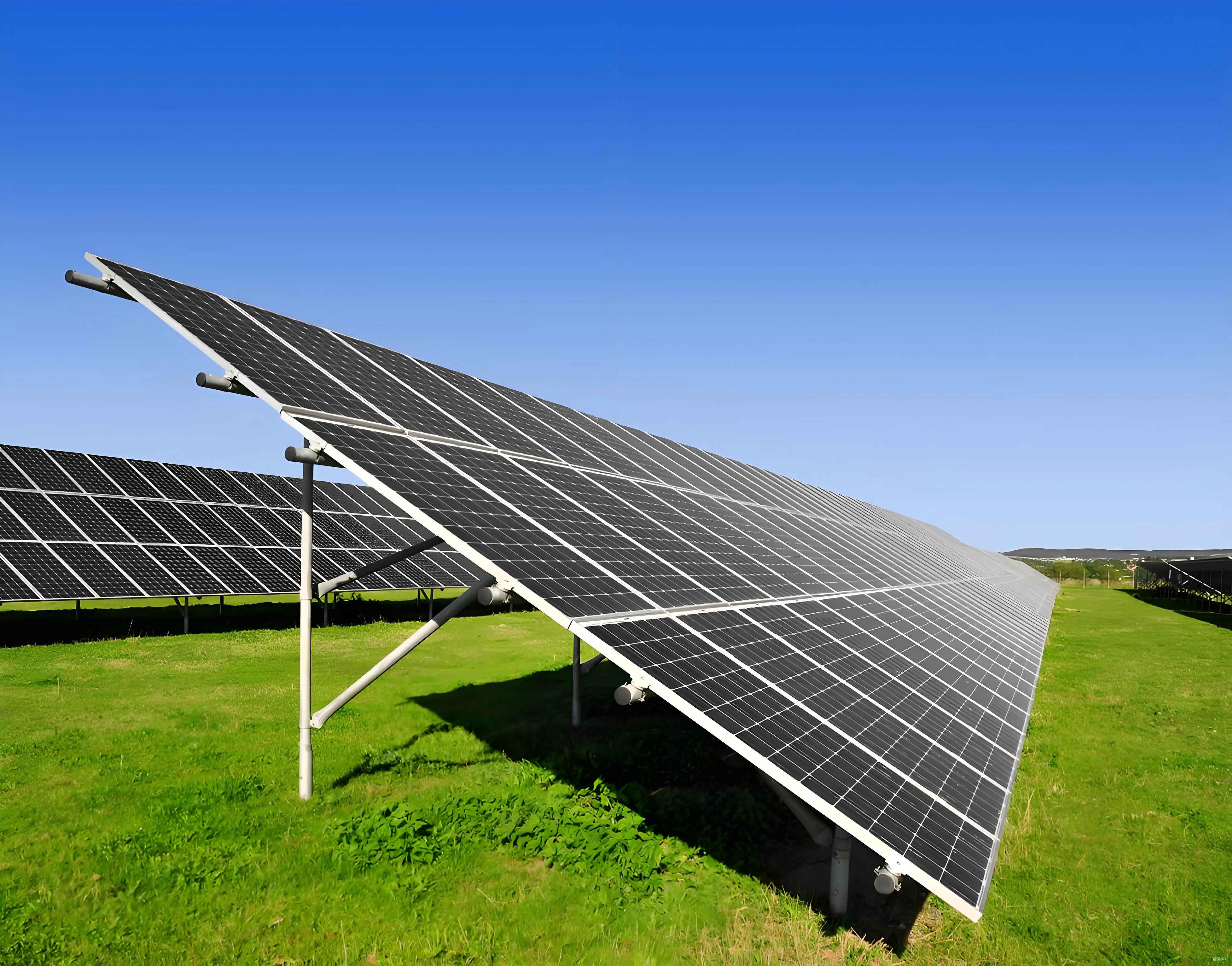
In the maintenance of solar panels, the efficiency and durability of photovoltaic systems are heavily dependent on regular cleaning to prevent dust and debris accumulation. As a key component, the walking mechanism of a photovoltaic panel cleaning robot ensures stable movement across the surface of solar panels. This mechanism features a symmetrical structure on both sides, comprising a walking synchronous belt, synchronous belt transmission mechanism, auxiliary support wheel mechanism, and a walking mechanism support frame. The support frame is critical as it bears the robot’s total mass and withstands the axial force from the synchronous belt, making it prone to fracture and deformation. In this study, I focus on the static analysis of the walking mechanism support frame using finite element methods to verify its design adequacy and identify potential optimization areas.

The walking mechanism support frame integrates components such as the drive wheel bracket, driven wheel bracket, support crossbeam, and reinforcing ribs into a single entity. To streamline the analysis, I modeled the support frame in SolidWorks, leveraging its advanced sheet metal module for efficient design of features like flanges and thin sheets. The model was saved in SolidWorks’ native SLDPRT format and imported into ANSYS Workbench via a plugin, which preserves structural characteristics and simplifies the process. Given that small features like holes and fillets minimally impact results but increase computational load, I simplified the model by removing such details. Additionally, other structures like the cleaning mechanism and chassis were not modeled explicitly; instead, static loads were applied at relevant nodes to represent their effects.
Material selection is crucial for meeting the technical requirement that the robot’s total mass should not exceed 10 kg. I chose aluminum alloy 6061 for the walking mechanism support frame due to its favorable strength-to-weight ratio. The material properties are summarized in the table below:
| Component | Material | Elastic Modulus (GPa) | Poisson’s Ratio | Density (kg/m³) |
|---|---|---|---|---|
| Support Crossbeam | AL6061 | 69 | 0.33 | 2700 |
| Drive Wheel Bracket | AL6061 | 69 | 0.33 | 2700 |
| Driven Wheel Bracket | AL6061 | 69 | 0.33 | 2700 |
Mesh generation in ANSYS Workbench is a vital step that influences the accuracy and efficiency of the simulation. I considered several factors: mesh quantity, where increasing elements improves precision up to a saturation point; mesh density, with finer grids in high-stress gradient regions like stress concentration areas; element order, where higher-order elements offer better curve approximation but require more computational resources; and mesh quality, assessed using metrics such as skewness, which should ideally be close to 0. For this analysis, I employed a combination of tetrahedral meshing for the drive and driven wheel brackets (where stress concentrations occur) and automatic meshing for other parts. Global mesh settings included a relevance of 20 and a fine relevance center. After refinement, the mesh comprised 113,511 nodes and 57,965 elements, with an average skewness of 0.35 and only about 0.8% of elements exceeding 0.95, indicating satisfactory quality.
Applying constraints and loads accurately is essential for realistic simulation. The support frame is fixed at its contact points with the auxiliary support wheel mechanism, representing full constraint. The primary loads include the robot’s gravity and the axial force from the synchronous belt. The axial force \( F_Q \) is calculated using the formula for belt drives:
$$ F_Q = \frac{1000 P_d}{v} $$
where \( P_d \) is the design power and \( v \) is the belt speed. The design power is derived from:
$$ P_d = K_A P_m $$
with \( P_m \) as the nominal power (0.07 kW), \( K_A \) as the service factor (1.2), and \( v \) computed as:
$$ v = \frac{\pi d_1 n_1}{6 \times 10^4} $$
Here, \( d_1 \) is the pitch diameter of the larger pulley (56.6 mm), and \( n_1 \) is the rotational speed of the smaller pulley (50 rpm). Substituting the values:
$$ v = \frac{\pi \times 56.6 \times 50}{6 \times 10^4} \approx 0.15 \, \text{m/s} $$
$$ P_d = 1.2 \times 0.07 = 0.084 \, \text{kW} $$
$$ F_Q = \frac{1000 \times 0.084}{0.15} = 560 \, \text{N} $$
For the gravitational load, the total mass of the robot is 80 kg, resulting in a weight force:
$$ F = \sum_{i=1}^{n} m_i g = 80 \times 10 = 800 \, \text{N} $$
Since the load is distributed symmetrically, each side of the walking mechanism carries approximately 400 N. Thus, the support frame is subjected to a combined load of 560 N axial force and 400 N gravitational load.
The static analysis results reveal the stress and deformation distributions. The equivalent stress nephogram shows a maximum stress of 31.12 MPa, while the deformation nephogram indicates a maximum deformation of 0.04 mm. These values are well within the allowable limits for aluminum alloy 6061, confirming that the design meets the operational requirements for photovoltaic panel cleaning robots. The low deformation and stress levels also suggest significant potential for lightweight optimization in future iterations.
In conclusion, the walking mechanism support frame for the photovoltaic panel cleaning robot was successfully analyzed using finite element methods. The modeling and simplification in SolidWorks, followed by detailed mesh generation and load application in ANSYS Workbench, provided accurate insights into its structural behavior. The maximum stress of 31.12 MPa and deformation of 0.04 mm demonstrate the frame’s adequacy for supporting the robot on solar panels. This analysis serves as a foundation for further optimization, potentially reducing material usage while maintaining performance. As the demand for efficient maintenance of photovoltaic systems grows, such analyses are crucial for enhancing the reliability and efficiency of cleaning robots, ensuring prolonged service life of solar panels.
