
In today’s era of increasing environmental awareness and energy challenges, the adoption of renewable energy sources has become paramount. Among these, solar energy stands out due to its abundance and sustainability. In this article, I will delve into the practical application of a solar photovoltaic grid-connected system, commonly referred to as a solar system, in a modern building project. The focus is on the design, implementation, and evaluation of such a solar system, highlighting its multifaceted benefits. Throughout this discussion, the term “solar system” will be frequently used to emphasize the integrated nature of photovoltaic technology in architectural contexts. The insights shared here are based on firsthand experience and technical analysis, aiming to provide a thorough understanding of how solar systems can be effectively harnessed.
The integration of a solar system into buildings is not merely a trend but a necessary step toward reducing carbon footprints and enhancing energy independence. This solar system project was undertaken to demonstrate the viability of grid-connected photovoltaic solutions in urban settings. By leveraging solar radiation, the solar system converts sunlight directly into electricity, feeding it into the local grid. This process eliminates the need for battery storage, thereby simplifying the solar system’s architecture and improving overall efficiency. In the following sections, I will explore various aspects of this solar system, from its foundational principles to its economic and social impacts, ensuring that the keyword “solar system” is adequately represented to underscore its importance.
To begin, let’s consider the broader context of solar systems in construction. Buildings account for a significant portion of global energy consumption, and incorporating solar systems can substantially offset this demand. The solar system discussed here is designed to be scalable and adaptable, making it a model for future projects. As I recount the journey of implementing this solar system, I will include detailed tables and formulas to elucidate key points. These elements will help quantify the performance and benefits of the solar system, providing a robust framework for evaluation. Moreover, the inclusion of visual aids, such as the following image, can enhance comprehension of the solar system’s setup:
This image depicts a typical solar system installation, showcasing the array of photovoltaic modules. It serves as a reference for the physical layout discussed later. Now, moving to the core content, I will structure the article into several key sections: project overview, working principles, system components, detailed design, benefit analysis, and conclusions. Each section will reinforce the centrality of the solar system in achieving sustainable building goals.
Project Overview and Context
The project involved the installation of a solar system on a high-rise building located in a region with favorable solar insolation. While specific details like names and addresses are omitted to maintain privacy, the geographical and climatic conditions are representative of many urban areas. The building stands at approximately 88 meters with 23 above-ground floors and 2 underground levels, covering a total area of around 27,829 square meters. This solar system was integrated during the late stages of construction, aligning with green building certification standards. The decision to incorporate a solar system was driven by the goal of achieving energy efficiency and reducing operational costs. The solar system’s capacity was tailored to the building’s energy profile, ensuring optimal utilization of available rooftop space.
In planning this solar system, we conducted extensive site assessments to determine the feasibility of photovoltaic integration. Factors such as shading, structural load, and orientation were meticulously analyzed. The solar system was designed to be non-intrusive, blending with the building’s aesthetics while maximizing energy capture. This approach underscores how a well-planned solar system can enhance both functionality and design. The solar system’s implementation followed rigorous engineering protocols, ensuring safety and reliability. As I proceed, I will elaborate on the technical nuances that make this solar system a benchmark for similar projects.
Working Principles of the Solar System
The fundamental operation of a solar photovoltaic grid-connected system revolves around the conversion of solar energy into electrical power without intermediate storage. In this solar system, photovoltaic modules composed of silicon cells absorb photons from sunlight, generating direct current (DC) electricity. The DC output is then channeled through a series of components that condition and invert it to alternating current (AC), synchronized with the utility grid. The solar system operates in parallel with the grid, meaning that when the solar system produces excess electricity, it is fed into the grid, and during periods of low solar input, power is drawn from the grid.
Mathematically, the power output of a solar system can be expressed using the photovoltaic effect principles. The current-voltage characteristics of a solar cell are given by the diode equation:
$$ I = I_L – I_0 \left( \exp\left(\frac{q(V + IR_s)}{nkT}\right) – 1 \right) – \frac{V + IR_s}{R_{sh}} $$
Where \( I \) is the output current, \( I_L \) is the light-generated current, \( I_0 \) is the reverse saturation current, \( q \) is the electron charge, \( V \) is the voltage, \( R_s \) is series resistance, \( n \) is the ideality factor, \( k \) is Boltzmann’s constant, \( T \) is temperature, and \( R_{sh} \) is shunt resistance. For a solar system comprising multiple cells, these parameters aggregate to determine the overall performance.
In a grid-connected solar system, the inverter plays a critical role by ensuring the AC output matches the grid’s frequency and phase. The inverter’s efficiency, denoted as \( \eta_{\text{inv}} \), affects the net output. Thus, the actual AC power from the solar system can be modeled as:
$$ P_{\text{AC}} = P_{\text{DC}} \times \eta_{\text{inv}} $$
Where \( P_{\text{DC}} \) is the DC power from the photovoltaic array. This solar system employs maximum power point tracking (MPPT) technology in the inverters to optimize \( P_{\text{DC}} \) under varying irradiance conditions. The absence of batteries in this solar system reduces losses associated with charge-discharge cycles, enhancing the overall efficiency. I will later quantify these efficiencies in the design section.
The solar system’s interaction with the grid is governed by safety standards to prevent islanding and ensure stable operation. Protective devices within the solar system monitor parameters like voltage and frequency, disconnecting if anomalies are detected. This seamless integration highlights the sophistication of modern solar systems in maintaining grid integrity while contributing clean energy.
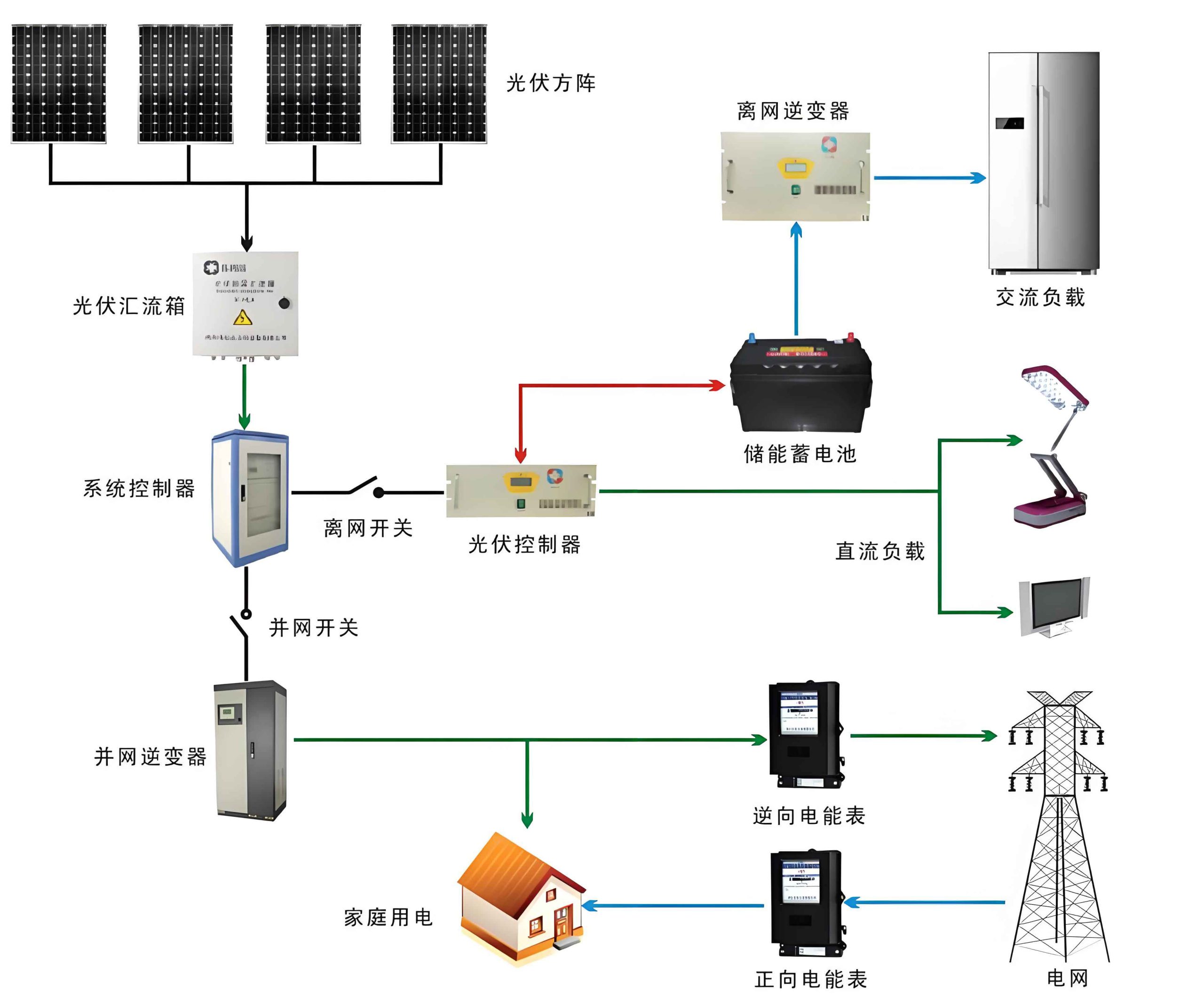
System Components and Configuration
A solar photovoltaic grid-connected system consists of several key components that work in unison. For this solar system, the major elements include the photovoltaic module array, combiner boxes, DC distribution cabinets, inverters, AC distribution cabinets, bidirectional meters, and monitoring systems. Each component is essential for the reliable operation of the solar system. To provide a clear overview, I have compiled a table detailing these components and their functions within the solar system:
| Component | Description | Role in Solar System |
|---|---|---|
| Photovoltaic Modules | Made of multicrystalline silicon, each rated at 250 Wp, with a voltage of 29.8 V. | Convert sunlight into DC electricity; the primary energy capture unit of the solar system. |
| Combiner Boxes | Enclosures that combine multiple strings of modules, equipped with fuses and surge protection. | Aggregate DC outputs and provide safety features for the solar system. |
| DC Distribution Cabinet | Panel that routes combined DC power to inverters, includes circuit breakers and monitoring. | Manages DC side distribution and protection in the solar system. |
| Inverters | Grid-tie inverters with MPPT, converting DC to AC; three units each rated at 20 kW. | Heart of the solar system, enabling grid compatibility and power optimization. |
| AC Distribution Cabinet | Switchgear that connects inverter outputs to the grid, with isolation and metering. | Facilitates AC side integration and control in the solar system. |
| Bidirectional Meter | Measures electricity flow to and from the grid, recording net consumption/generation. | Quantifies the solar system’s contribution and enables financial settlements. |
| Monitoring System | Data acquisition unit that tracks performance parameters like voltage, current, and energy. | Provides real-time oversight and diagnostics for the solar system. |
This solar system utilizes 200 photovoltaic modules arranged in 10 strings of 20 modules each. The strings are connected to combiner boxes, which then feed into the DC distribution cabinet. From there, the DC power is inverted to AC by the three inverters, synchronized to the 380 V three-phase grid. The AC output is routed through the AC distribution cabinet and bidirectional meter before being fed into the building’s electrical system. The entire solar system is monitored 24/7 to ensure optimal performance and early fault detection.
The design of this solar system emphasizes modularity and scalability. For instance, the photovoltaic array can be expanded if additional roof space becomes available. Similarly, the inverter capacity can be adjusted to match future upgrades. This flexibility is a hallmark of well-engineered solar systems, allowing for adaptation to changing energy needs. The solar system’s components were selected based on durability and efficiency ratings, ensuring a long operational life with minimal maintenance.
Detailed Design Considerations
The design of a solar system hinges on accurate assessment of local solar resources and precise engineering calculations. For this solar system, we began by analyzing the solar radiation data for the region. The average annual solar irradiance is approximately 4986 MJ/m², with monthly variations. The peak irradiance occurs in summer months, aligning with higher energy demand. To quantify the available energy, we use the formula for annual solar radiation on a tilted surface:
$$ H_t = H_b R_b + H_d R_d + H \rho R_r $$
Where \( H_t \) is the total irradiance on the tilted surface, \( H_b \) is beam radiation, \( H_d \) is diffuse radiation, \( H \) is global horizontal radiation, \( \rho \) is ground reflectance, and \( R_b, R_d, R_r \) are conversion factors for beam, diffuse, and reflected components, respectively. For this solar system, the tilt angle was set equal to the local latitude of about 32° to maximize annual yield.
The orientation of the solar system’s modules is crucial. The azimuth angle was chosen as due south to capture the maximum sunlight throughout the day. The spacing between rows of modules was calculated to prevent shading, using the formula for shadow length:
$$ L = h \cot(\alpha_s) $$
Where \( h \) is the height of the module, and \( \alpha_s \) is the solar altitude angle at the winter solstice. For this solar system, a spacing of 25 mm between adjacent modules was maintained to allow for thermal expansion and airflow.
Next, we determined the number of modules required for the solar system. The total DC power rating is given by:
$$ P_{\text{DC, total}} = N_{\text{modules}} \times P_{\text{module}} $$
With 200 modules of 250 Wp each, \( P_{\text{DC, total}} = 50,000 \text{ Wp} \). The area occupied by the solar system’s array is calculated considering module dimensions and spacing. Each module measures 1.65 m by 0.991 m, and with spacing, the effective area per module is 1.7 m². Thus, the total area for 200 modules is 340 m², but accounting for array gaps, the actual rooftop area needed is 561 m². This efficient use of space demonstrates how a solar system can be integrated into limited urban footprints.
The electrical design of the solar system involves sizing the inverters and cables. The inverter input voltage must match the string voltage, which for 20 modules in series is:
$$ V_{\text{string}} = 20 \times 29.8 \text{ V} = 596 \text{ V} $$
This falls within the typical input range of grid-tie inverters. The DC and AC cable sizes were selected based on current-carrying capacity and voltage drop criteria. For instance, the maximum current per string is:
$$ I_{\text{string}} = \frac{P_{\text{string}}}{V_{\text{string}}} = \frac{20 \times 250}{596} \approx 8.39 \text{ A} $$
Using standard tables, we chose cables with adequate cross-sectional area to minimize losses. The solar system’s overall efficiency is affected by various factors, which I will summarize in a table:
| Factor | Efficiency Coefficient | Description |
|---|---|---|
| Module Tolerance | 0.95 | Allowed deviation from rated power due to manufacturing. |
| Soiling Losses | 0.93 | Reduction from dust and debris accumulation on modules. |
| Inverter Efficiency | 0.88 | Conversion efficiency from DC to AC, including MPPT losses. |
| System Degradation | 0.996 per year | Annual decrease in module performance over time. |
The combined system efficiency for the solar system is the product of these coefficients: \( \eta_{\text{sys}} = 0.95 \times 0.93 \times 0.88 = 0.777 \) or 77.7%. This efficiency is applied to calculate the actual annual energy generation. The theoretical annual energy output is derived from the solar radiation data and module area:
$$ E_{\text{theoretical}} = H_{\text{annual}} \times A_{\text{array}} \times \eta_{\text{module}} $$
Where \( H_{\text{annual}} = 4986 \text{ MJ/m}^2 = 4986 \times 0.2778 \text{ kWh/m}^2 \approx 1385 \text{ kWh/m}^2 \) (using conversion 1 MJ = 0.2778 kWh), \( A_{\text{array}} = 327.36 \text{ m}^2 \) (total module area), and \( \eta_{\text{module}} = 0.145 \) (module efficiency). Thus:
$$ E_{\text{theoretical}} = 1385 \times 327.36 \times 0.145 \approx 66,268 \text{ kWh} $$
Applying the system efficiency, the actual annual output of this solar system is:
$$ E_{\text{actual}} = 66,268 \times 0.777 \approx 51,504 \text{ kWh} $$
Over a 25-year lifespan, accounting for degradation, the total energy yield can be estimated using a geometric series. If degradation is 0.4% per year, the output in year \( n \) is \( E_n = E_{\text{actual}} \times (0.996)^{n-1} \). The cumulative output is:
$$ E_{\text{cumulative}} = E_{\text{actual}} \sum_{n=1}^{25} (0.996)^{n-1} $$
This sums to approximately 1,227,600 kWh, demonstrating the long-term viability of the solar system.
The grid connection for this solar system follows standard protocols for distributed generation. A single point of interconnection at 380 V was established, with protective relays to ensure anti-islanding. The bidirectional meter records net energy flows, enabling feed-in tariffs and self-consumption accounting. This design ensures that the solar system operates harmoniously with the existing electrical infrastructure.
Comprehensive Benefit Analysis
The implementation of a solar system yields both social and economic benefits. From a social perspective, the solar system contributes to environmental sustainability by reducing greenhouse gas emissions. By displacing fossil fuel-based electricity, the solar system mitigates air pollution and climate change impacts. Additionally, the solar system serves as an educational tool, raising awareness about renewable energy among building occupants and the community. The solar system also reduces the urban heat island effect, as the photovoltaic modules shade the rooftop, lowering cooling demands in summer.
Economically, the solar system offers attractive returns on investment. The initial costs include equipment, installation, and engineering. For this solar system, the investment breakdown is summarized in the table below:
| Cost Category | Amount (USD) | Percentage of Total |
|---|---|---|
| Photovoltaic Modules | 210,000 | 41.95% |
| Electrical Equipment and Cabling | 96,500 | 19.28% |
| Mounting Structures and Grounding | 54,000 | 10.78% |
| Monitoring and Data Acquisition | 20,000 | 3.99% |
| Installation, Training, and Design | 120,000 | 23.97% |
| Total Investment | 500,500 | 100% |
Note: Costs are approximated based on market rates and scaled for illustration.
The revenue from the solar system arises from electricity savings and feed-in tariffs. Assuming an electricity price of $0.141 per kWh, a national subsidy of $0.042 per kWh for 20 years, and a local subsidy of $0.025 per kWh for 15 years, the annual revenue in the first year can be calculated as:
$$ R_{\text{year1}} = E_{\text{actual}} \times (P_{\text{retail}} + S_{\text{national}} + S_{\text{local}}) $$
Where \( P_{\text{retail}} = 0.141 \), \( S_{\text{national}} = 0.042 \), and \( S_{\text{local}} = 0.025 \). Thus:
$$ R_{\text{year1}} = 51,504 \times (0.141 + 0.042 + 0.025) = 51,504 \times 0.208 = 10,713 \text{ USD} $$
Considering annual degradation of 0.4% and an inflation rate of 0.4% for energy prices, the revenue over time can be modeled. The net present value (NPV) of the solar system investment is given by:
$$ \text{NPV} = -C_0 + \sum_{t=1}^{T} \frac{R_t}{(1 + r)^t} $$
Where \( C_0 = 500,500 \) USD is the initial cost, \( R_t \) is the revenue in year \( t \), \( r \) is the discount rate (assumed 5%), and \( T = 25 \) years. Using conservative estimates, the payback period for this solar system is approximately 5 years, after which it generates pure profit. This economic analysis underscores the financial attractiveness of deploying a solar system in commercial buildings.
Furthermore, the solar system enhances the building’s market value and compliance with green building standards. Certifications like LEED or BREEAM award points for renewable energy integration, which this solar system facilitates. The long-term energy price stability provided by the solar system shields the building from utility rate fluctuations, adding to its economic resilience.
Extended Discussion on Solar System Optimizations
To maximize the benefits of a solar system, ongoing optimizations are essential. For instance, the performance of this solar system can be enhanced through regular maintenance, such as cleaning the modules to mitigate soiling losses. Monitoring data from the solar system can identify underperforming strings or inverters, enabling prompt repairs. Additionally, integrating energy storage with the solar system, though not included in this project, could further increase self-consumption and grid independence.
Technological advancements in photovoltaic materials, such as perovskite cells, may future-proof the solar system by allowing retrofits with higher-efficiency modules. The solar system’s design also considered potential expansions; for example, additional modules could be installed on vacant roof areas to increase capacity. The inverters in this solar system are compatible with smart grid features, enabling demand response and grid support services.
From a policy perspective, the success of this solar system hinges on supportive regulations. Feed-in tariffs, net metering, and tax incentives are crucial for improving the economics of solar systems. I advocate for policymakers to strengthen these measures to accelerate solar system adoption. Moreover, public-private partnerships can fund large-scale solar system deployments, driving down costs through economies of scale.
The environmental impact of the solar system extends beyond emission reductions. The life-cycle assessment of photovoltaic modules indicates that the energy payback time—the period required for the solar system to generate the energy used in its production—is typically 1-3 years. Given the 25-year lifespan, the solar system net contributes significant clean energy. This aligns with circular economy principles, as modules can be recycled at end-of-life to recover materials.
Conclusions and Future Outlook
In conclusion, the implementation of a solar photovoltaic grid-connected system in this building project demonstrates the practical viability and multifaceted benefits of solar energy. The solar system effectively harnesses solar radiation to generate electricity, reducing reliance on conventional power sources and lowering environmental impact. Through detailed design and rigorous analysis, this solar system achieves both social and economic gains, serving as a model for future installations.
The key takeaways from this solar system project include the importance of accurate resource assessment, efficient component selection, and comprehensive benefit evaluation. The solar system’s design prioritized integration with existing infrastructure, ensuring seamless operation. As solar technology continues to evolve, future solar systems will likely become even more efficient and cost-effective, further solidifying their role in sustainable development.
I encourage building owners, architects, and engineers to consider incorporating solar systems into their projects. The initial investment is offset by long-term savings and environmental stewardship. By embracing solar systems, we can collectively move toward a cleaner, more resilient energy future. This solar system case study underscores that with careful planning and execution, renewable energy solutions are not only feasible but also profitable and beneficial for society.
Looking ahead, innovations like building-integrated photovoltaics (BIPV) could merge solar systems directly into building materials, enhancing aesthetics and functionality. Research into tandem cells and improved inverter technologies will boost the performance of solar systems. Ultimately, widespread adoption of solar systems will play a pivotal role in mitigating climate change and achieving global energy sustainability goals.