
The lighting system is an indispensable auxiliary operation system in mining areas. With the continuous expansion of production, the workload that the lighting system can withstand is also increasing. In the process of building a “smart mine”, unmanned, safe, efficient, and clean have become the goals of mine construction.As a new type of environmentally friendly energy source, solar energy has been widely used in daily life. With the continuous development of science and technology, solar photovoltaic technology is becoming more and more mature. The implementation of solar-powered smart street lights in mining areas can greatly save energy consumption brought by the lighting system.
However, currently there are few solar street lights used in mining areas, and they mostly use a single control method, which is “use when there is power, stop when there is no power”, which is seriously affected by factors such as season and weather, without intelligent energy management strategies.Therefore, many experts have conducted research on the characteristics and influencing factors of atmospheric visibility changes, in order to switch the lighting mode of street lights according to visibility, and achieve energy consumption control of street lights.Saadatseresht M et al. studied the application of artificial neural networks in visibility prediction, and proposed a new technology based on artificial neural networks for visibility uncertainty prediction (AVUP). They achieved visibility prediction by training a feedforward multilayer artificial neural network.Duddu et al. developed a feedforward backpropagation neural network (BPNN) model to predict fog/low visibility conditions, and applied it to road link levels.Wang et al. used visible light-infrared images to estimate the visible range, and proposed a multi-modal deep fusion structure based on CNN to learn robust joint features of two sensor modalities.Gu Kuo et al. proposed a composite model based on machine learning – gray correlation analysis (GRA) – improved complete empirical mode decomposition (ICEEMD) – long short-term memory (LSTM) model to predict PM2.5 concentration and visibility.Zhu Juxiang et al. used the IF-SVMD-BWO-LSTM model to decompose the PM2.5 sequence, predict each sub-sequence after decomposition, and use the BWO algorithm to optimize the weights and thresholds of LSTM to improve the model prediction accuracy.Fang Nan et al. used long short-term memory neural network (LSTM) model to simulate hourly visibility, and compared the simulation effects of observing visibility as an input variable or not.Currently, there are many studies on atmospheric visibility, but most of them are used in the lighting of living areas, and there are few studies on the lighting system of mining areas. Moreover, most of the mining area street lights use direct power supply, which consumes a lot of energy.
Based on the above problems, this article designs a solar-powered smart streetlight system for mining areas. On the basis of traditional streetlights, neural network models are used to collect data on the visibility of mining areas’ lighting spaces and predict their possible values over the next period of time, so as to set corresponding power supply strategies and achieve the rational use of stored solar energy, allowing the solar-powered smart streetlights to achieve maximum sustainable power supply.
1. Visibility prediction and power saving strategy
Due to the vulnerability of solar energy to seasonal, weather, day and night, etc., the solar street light system needs to design a reasonable energy-saving method to overcome the impact of the environment.Research on visibility self-learning prediction model and power saving strategy to achieve self-learning prediction of visibility;based on this, make corresponding power saving strategies.
1.1 Visibility self-learning prediction model
Adaboost algorithm is an ensemble learning algorithm that achieves accurate correction of classifier or decision model parameters through iterative methods, thereby improving the accuracy of the prediction model’s prediction results.It is usually used in conjunction with other classifiers or prediction models. The prediction model in this article is implemented based on the recurrent neural network LSTM algorithm, and the Adaboost algorithm is used to modify the LSTM model parameters to form an Adaboost-LSTM model with high prediction performance.Adaboost continuously iterates to change the weights of the training samples of the prediction model, reducing the role of the training samples with classification errors in the voting results, thereby improving the overall prediction accuracy.
The construction of the Adaboost-LSTM model mainly consists of the following 7 steps:
Step1 Determine the input and output of the LSTM prediction model;
Step2: Initialize the weights of the training dataset for the prediction model.
The ownership values are set to be the same during initialization, so the weight values of the samples during the first training are:
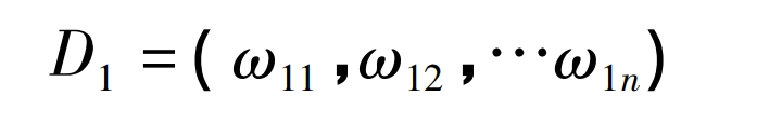
where: ω1i = 1/n, i = 1, 2, 3, …n,
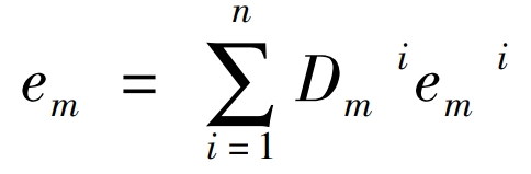
Step3: Begin model training, or the iterative process. At the kth training iteration, the distribution of sample weights is Dm, and the model obtains a poor predictor hm. Calculate the prediction error em^i for the sample corresponding to hm;
Step4 Calculate the total error rate of the training samples:
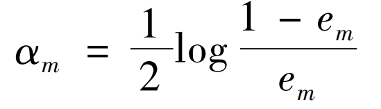
Step5 Calculate the coefficients of the weak predictor after k times of training:
Step6 Update the sample weight:
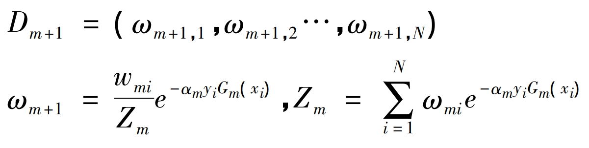
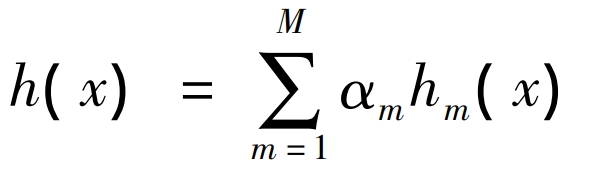
Step7 Construct a strong predictor:
After the prediction model is trained, using the third-party toolkit pyQt that comes with Python, an interactive tool for the prediction model and control instructions is designed, and a GUI interface is implemented to achieve the intelligent control of the street lamp node controller based on the output results of the prediction model.
1.2 Power saving strategy
The power saving strategy is mainly formulated based on different visibility levels. Currently, the color of the lamp beads of street lamps mainly includes white lamp beads, yellow lamp beads, and yellow-white mixed lamp beads. The adaptive solar street lamp system designed in this article is divided into three different lighting modes according to the different lamp beads, namely: white light, yellow light, and yellow-white mixed light.Using LSTM to predict visibility V, the color of the light is adjusted according to different V values, thus achieving the management of different power lights and achieving the goal of power saving.For the light, yellow light has strong penetrating power, while white light has high color temperature.Therefore, when the visibility is high, corresponding to V>10km, the white light with weak penetrating power is lit.When the visibility V<5km, the yellow light with strong penetrating power is lit. When the visibility is 5km≤V≤10km, the yellow-white light is lit. According to the above analysis, the lighting modes are summarized as shown in Table 1.
| Visibility/km | Lighting mode |
| 10 < V | White light |
| 5 ≤ V ≤ 10 | Yellow light |
| V < 5 | White yellow light |
In practical applications, solar street lights cannot avoid being affected by factors such as seasons, day and night, and weather. In order to increase their stability and maximize their ability to provide continuous power, it is necessary to design power-saving strategies to solve the problem of insufficient power. This article designs a power-saving strategy as shown in Table 2.
| Future visibility/km | Energy saving method | Energy saving strategy |
| 10 < V | Power saving method | 1Q |
| 5 ≤ V ≤ 10 | Power saving method 2.0 | 0.9Q |
| V < 5 | Power saving method 3.0 | 0.8Q |
When it comes to electric energy, adjusting the power used can achieve the goal of adjusting the amount of electric energy used. The smart streetlight system can predict the future visibility value, and adjust the streetlight lighting power reasonably according to the predicted value, thus designing a power-saving method for the system.Visibility is divided into 3 levels, when it is at the maximum level, that is, the highest visibility, the streetlight lighting power is set to Q, when it is at the minimum level, that is, the lowest visibility, the streetlight lighting power is set to 0.8Q, when it is at the intermediate level, the streetlight lighting power is set to 0.9Q, the adjustment of streetlight power is achieved by adjusting the current.
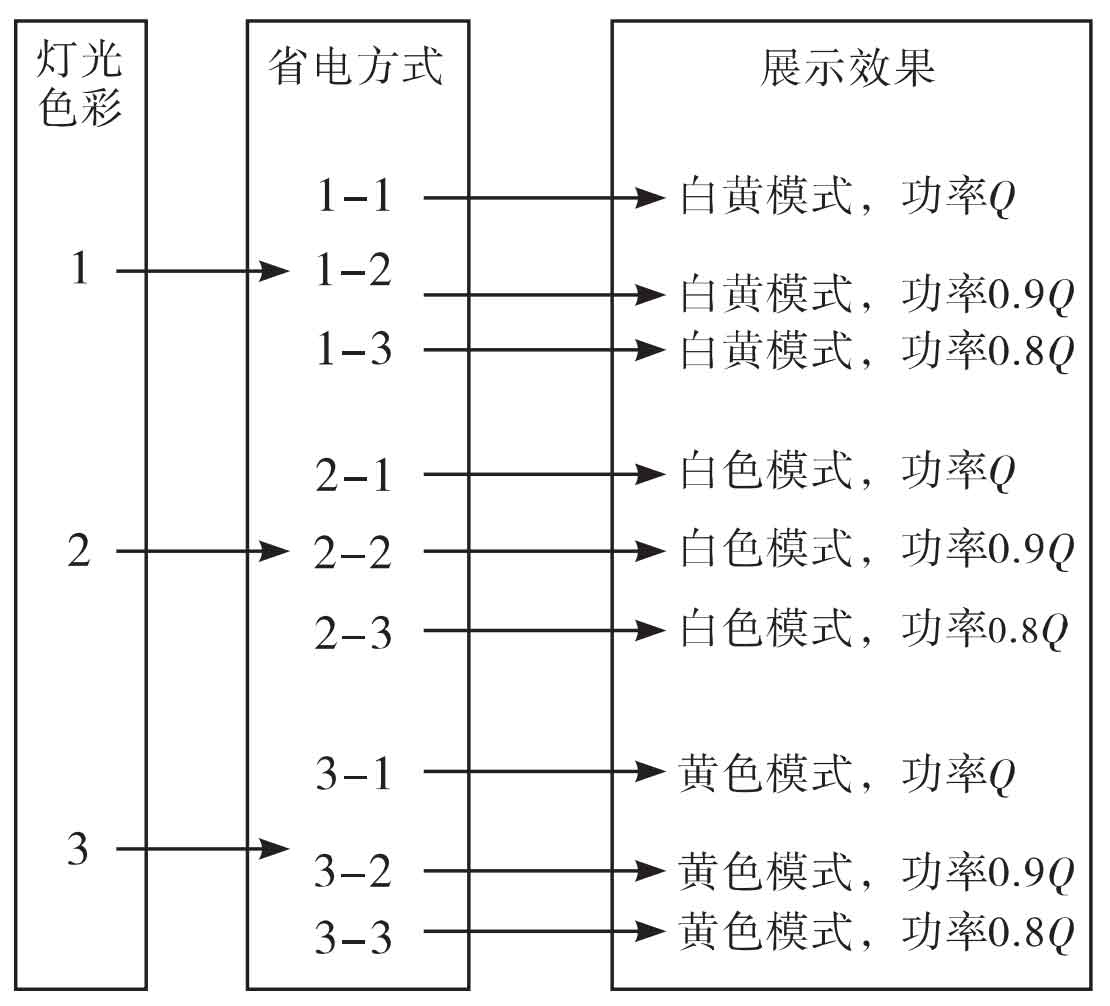
To sum up, based on considering the lighting color mode, power saving strategy, and power saving method, this article has reasonably set up specific power saving methods. According to the different lighting colors and lighting powers, a total of 9 power-saving lighting methods have been designed, and their topological structures are shown in Figure 1.
2. System network structure
In Section 1, the system power-saving strategy was reasonably designed. In this section, by analyzing the system network structure, the network topology and workflow of the system were designed.
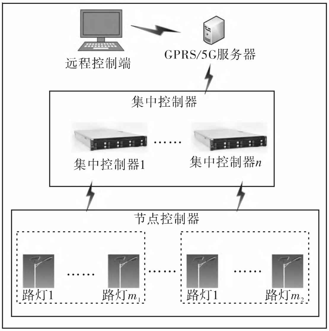
The network topology structure of the solar-powered smart streetlight system for mining areas is shown in Figure 2. The system mainly consists of four parts: streetlight node controllers, wireless communication systems, centralized controllers, and host computer monitoring terminals.The streetlight node controllers are installed on each streetlight to enable the selection of streetlight lighting modes and light intensity, directly controlling the operation of the streetlights.The centralized controllers are responsible for collecting and processing surrounding environmental data, analyzing the environmental data using a visibility prediction model, and outputting control instructions to the node controllers, thus achieving the purpose of adaptive adjustment of streetlight lighting effects.The centralized controllers are installed regionally, achieving local networking through the LoRa wireless communication system, and achieving stable wireless transmission of control instructions.The smart streetlight system platform end implements centralized monitoring of the entire streetlight system, transmitting control instructions through GPRS/5G wireless communication, while receiving signals from the centralized controller. The communication is not limited by distance, and the setting of the centralized monitoring station is flexible.
The overall use of IoT technology to centrally monitor and control the street lighting system in the entire mining area, with hierarchical management and control, to achieve stable and healthy operation of the street lighting system.
3. System software/hardware design and implementation
Based on the analysis of the network topology of the above systems, this section designs and implements the system software and hardware to complete the implementation of the entire mining area smart streetlight system and verify the reliability of the system.
3.1 System hardware design and implementation
The system hardware mainly consists of STM32 microcontrollers and LoRa wireless communication modules, which are applied to node controllers and centralized controllers.In the centralized controller, the microcontrollers control multiple sensors to collect external environmental data, and input the data into a predictive model to obtain the current visibility and predict the future visibility. Then, the control instructions output by the predictive model are transmitted to the node controller through wireless communication to control the lighting mode and color of the street lights, and implement corresponding power-saving strategies.
(1) Hardware design of node controller
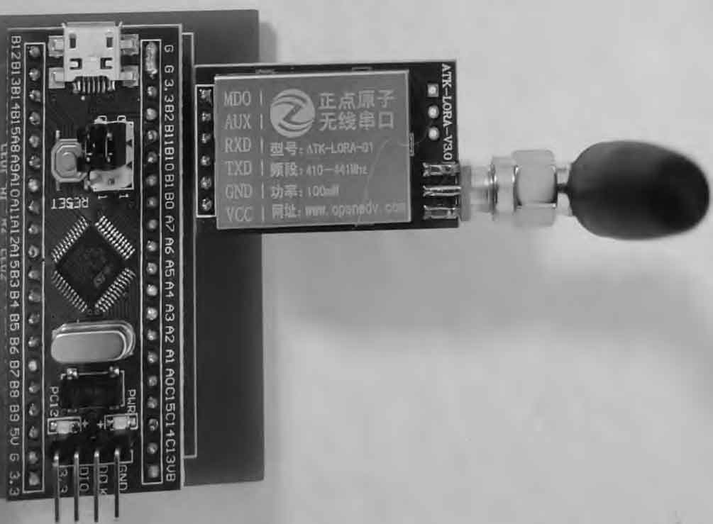
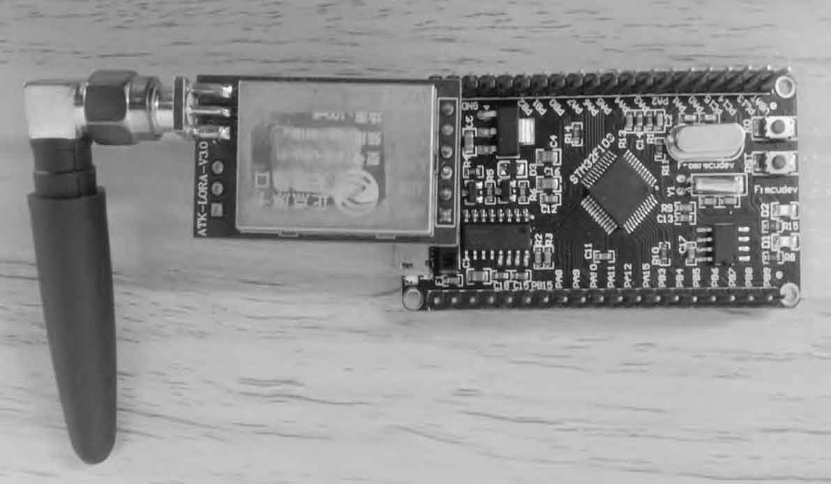
For the node controller, its main function is to receive control instruction signals from the centralized controller using LoRa wireless communication, and then flexibly switch the lighting mode of the street lamp according to the corresponding control instructions.The hardware of the system node controller mainly consists of a microprocessor, a wireless communication module, and a street lamp response module. The microprocessor uses the STM32 single-chip microcomputer, which is mainly responsible for controlling the orderly operation of external components. It controls the lighting mode of the street lamp by receiving the control instructions.The wireless communication uses the LoRa module, which has an effective communication distance of about 3 km and can achieve local networking, thereby improving the transmission efficiency of the signal. It mainly receives control instructions from the centralized controller. The street lamp response end responds to the control signal sent from the node controller and switches the lighting mode of the street lamp accordingly.The physical appearance of the street lamp node controller is shown in Figure 3.
(2) Hardware design of centralized controller
The hardware components of the centralized controller are similar to those of the node controller, but its functions are different from those of the node controller.The centralized controller is mainly responsible for data acquisition and processing. In addition to the microprocessor and wireless communication system, it also includes some sensors, such as temperature and humidity sensors using the SHT20 model, with measurement ranges of -40 to 125°C (temperature) and 0 to 100% RH (humidity). This sensor is small in size, low in power consumption, and completely suitable for the design of this system.In addition, it is also necessary to measure the concentration of particulate matter in the air, mainly PM2.5/PM2.10 concentration, using a sensor model HLPM025K3 to achieve the collection of particulate matter concentration in the air, with a measurement range of 0.1 to 1000 μg/m3.
The collected data of ambient temperature and humidity, as well as particulate matter concentration, are sent to the Adaboost-LSTM visibility prediction model to calculate the current visibility and predict the future visibility. Then, the instruction to control the street lamp lighting mode is output. The instruction is sent to the receiving end of the node controller through the wireless communication module LoRa, and the node controller executes the corresponding instruction to directly control the street lamp lighting mode.In addition, it is necessary to use 5G/GPRS signals to transmit data to the upper computer monitoring terminal to achieve comprehensive centralized remote monitoring of the entire system.The physical diagram of the centralized controller is shown in Figure 4.
3.2 System software design and implementation
The software design mainly includes the control code of the node controller and the centralized controller, as well as the design of the remote monitoring platform. At the same time, the design of the data communication docking protocol completes the wireless communication local networking.
(1) Software design of centralized controller
The centralized controller is responsible for collecting surrounding environment data, processing the collected data, outputting control instructions, and transmitting them to the node controller through wireless Lora communication. At the same time, it also receives control instructions from the monitoring platform side as a medium for communication between the upper computer control terminal and the node control terminal.First, the system is initialized, mainly including the initialization of the work of various sensors and LoRa wireless communication modules. The collected data is sent to the LSTM prediction model to obtain the current visibility value V, and determine the current visibility level. When the visibility value is higher than 10, the control instruction to turn on the white light is output.When the visibility is lower than 5, the control instruction to turn on the yellow light is output, and the control instruction is stored.At the same time, the historical data and the currently stored lighting modes are input into the LSTM predictor to obtain the visibility value for the next 12 hours. Then, the corresponding power saving strategy is output based on the visibility value for the next 12 hours, and the power saving strategy is sent to the node controller to achieve intelligent control of the street lighting mode.
(2) Node controller software design
The node controller is the lowest layer for transmitting control instructions, responsible for receiving control instructions from the centralized controller. The software design mainly corresponds to LoRa wireless communication networking and converting the received control instructions into corresponding street lamp control methods.Firstly, the wireless communication module and control instruction output terminals need to be initialized, and the corresponding hardware working mode needs to be started. Then, the signal from the centralized controller is monitored in the form of broadcasting, and the corresponding instructions are output to the actuator through the control terminal.
(3) Software design of communication part
The system as a whole consists of three subsystems, from low to high: node controller, centralized controller, and remote monitoring terminal.The communication between the three subsystems is done through wireless communication.According to the instruction transmission process, the control instructions issued by the remote monitoring terminal are implemented through GPRS wireless communication. The centralized controller receives signals from GPRS and transmits them to the node controller through wireless communication LoRa. The node controller receives the control instructions and outputs them to the actuator.
The signal transmission between the centralized controller and the node controller is mainly completed through LoRa wireless communication.In this system, one centralized controller corresponds to multiple node controllers, achieving one-to-many local networking.When the system is working, the LoRa module installed on the node controller side always remains in working state, monitoring the signal from the centralized controller in a broadcast manner. Once the control signal is received, it will be converted into corresponding electrical signals to control the actuator side to change the lighting mode of the street lamp.In data communication, it is carried out in a master-slave mode, with the centralized controller as the master node, sending signals to its corresponding node controller in a time-sharing multiplexing manner. The node controller, as a slave node, cannot directly establish an information transmission channel with the centralized controller, but can only send a request to upload signals to the centralized controller first, and then wait for the centralized controller to return instructions. When receiving an idle instruction, the feedback signal can be successfully transmitted to the centralized controller.In this way, a complete local communication network is formed. Table 3 shows the data transmission format between the centralized controller and the node controller, setting the accurate flow of sending control signals.
| Frame header | 0x55 |
| Sender | 0x01 |
| Data length | 1 Byte |
| Effective data | 1 Byte |
| Verification code | 1 Byte |
| End of frame | 0x0d |
The centralized controller acts as a communication medium between the remote control terminal and the street lamp lighting actuator, receiving signals from the remote control terminal.The remote control terminal and the centralized controller use GPRS wireless communication, which relies on a server to complete the communication, breaking through the limitation of distance and enabling remote monitoring at any location. When transmitting signals, GPRS uses the GSM network to send the signals to the server, and the centralized controller receives the signals from the server. At the same time, the centralized controller can also send data to the server, and the remote monitoring terminal reads the data from the server to complete the transmission of signals.Reliable communication protocols can ensure smooth communication of wireless communication. The data communication protocol of the remote monitoring terminal is shown in Table 4. During data transmission, the data is transmitted in the form of a string bit by bit, and at the same time, it is determined whether the data is accepted or not.
| Frame header | 0x55 |
| Sender | 0x00 |
| Data length | 1 Byte |
| Model parameters | 8 Byte |
| Verification code | 1 Byte |
| End of frame | 0x0d |
3.3 System result display
(1) System monitoring platform
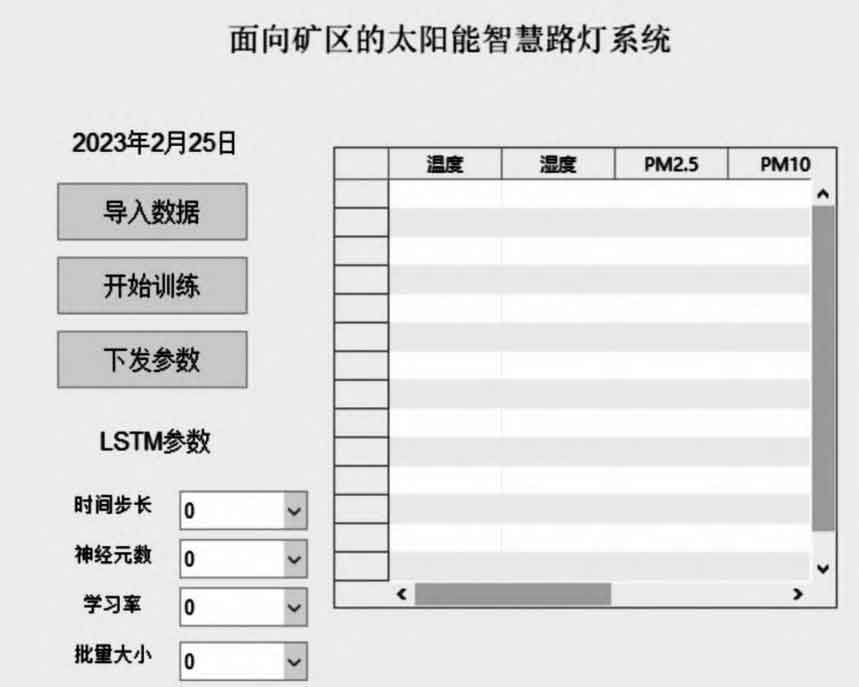
The remote monitoring platform of the system uses python’s built-in third-party toolkit pyQt to implement the interactive tool between the prediction model and the control instructions, and designs the GUI interface to achieve the intelligent control of the street lamp node controller based on the output results of the prediction model.The main interface of the system visibility prediction is shown in Figure 5.
The system monitoring platform mainly implements the following four functions:
① Parameter setting.Set the initialization parameters for the LSTM neural network;
② Model training.Import the dataset and set the corresponding parameters to start training;
③ Display the corresponding output results of model training on the interactive software interface;
④ Deliver parameters.As the model is trained, the prediction accuracy gradually improves. When the accuracy meets the requirements, the corresponding prediction model parameters are delivered.
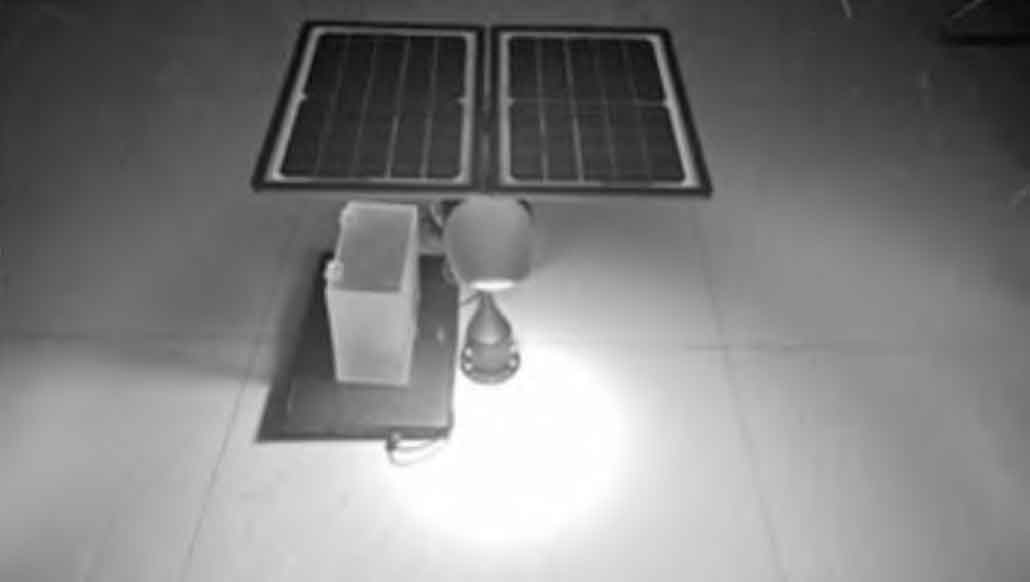
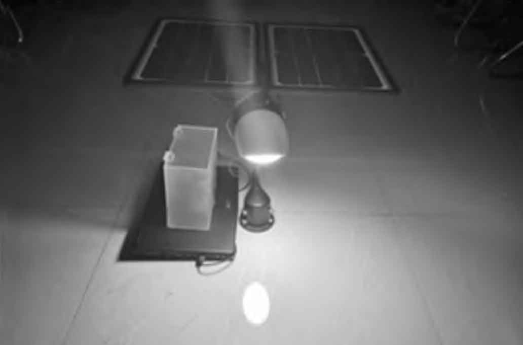
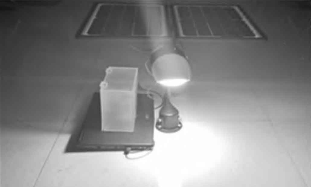
(2) Demonstration of physical effects
By simulating the surrounding environment, the verification of three lighting modes is achieved. When the visibility is within the corresponding range, the lights display the corresponding lighting effects, as shown in Figure 6.
4. Conclusion
This article is based on the research and design of solar energy for mining area street lamp systems.Adaboost algorithm is used to optimize LSTM neural network, establish Adaboost-LSTM model, set reasonable power-saving lighting methods, predict the output results of the neural network algorithm based on the model, adjust the lighting power and light color of the street lamp, so as to rationally use solar energy and maximize the solution to the problem that solar energy is easily affected by natural factors.Build software and hardware systems and remote control platforms, use single-chip microcontrollers as the control core, use wireless communication for networking, effectively connect the mining area street lamps, and ensure the reliability of system information transmission without relying on local networking of server networks.Through experimental verification, the system achieves reasonable planning of solar energy use based on future visibility, making solar street lamps more energy-efficient and reliable, completing the application of remote monitoring system in mining area lighting system, and promoting the further development of “smart mine” unmanned and clean.