1. Basic principles of DC/AC inverters
Inversion is the process of converting direct current into alternating current. AC side connected to the power grid, active inverter (solar grid connected inverter); The AC side is connected to the load and is a passive inverter (solar off grid inverter). Classification method for inverter circuits: classification of converter mode, output phase number, nature or purpose of DC power supply, etc. Solar inverters are divided into single solar inverters and three solar inverters based on the number of output phases. The inverter circuit can be divided into two-level inverter circuit and multi-level inverter circuit according to its output level. The basic principle of inverter is shown in Figure 1:
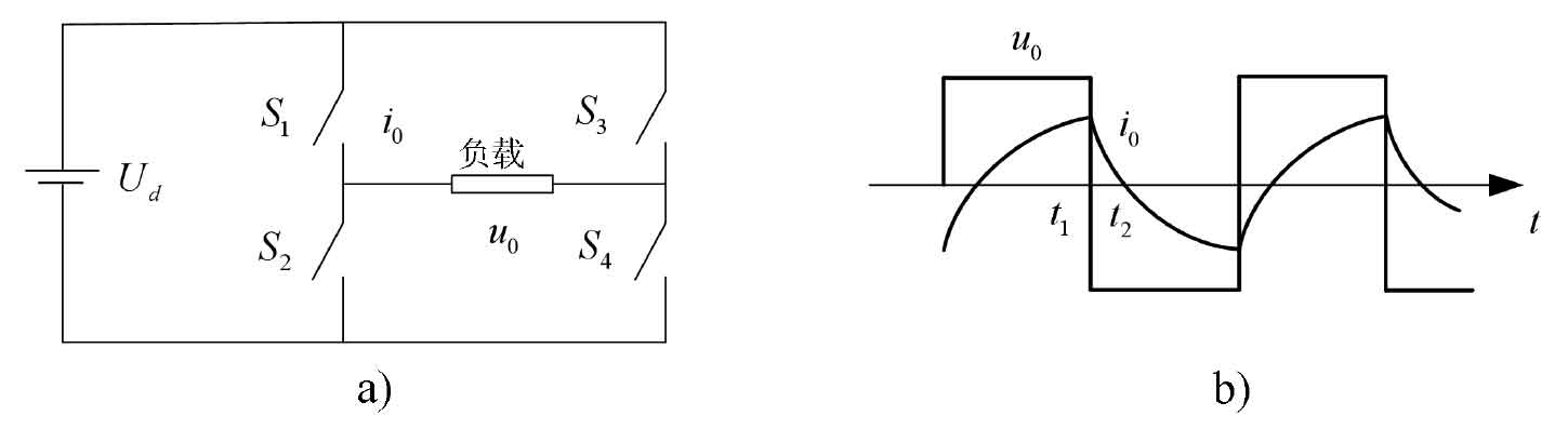
The commutation mode can be divided into two types:
Mode 1: When upper bridge arm S1 and lower bridge arm S4 are turned on, and lower bridge arm S2 and upper bridge arm S3 are disconnected, the voltage borne by the load at this time is Uo;
Mode 2: The upper bridge arm S1 and lower bridge arm S4 are disconnected, and the lower bridge arm S2 and upper bridge arm S3 are closed. At this time, the voltage borne by the load is – Uo, which converts the DC input into an AC output. If you want to change the frequency of the output AC power, changing the switching frequency of the two sets of switches can achieve a change in the output frequency.
2. SPWM control technology
Using a sine wave as the expected waveform output of the solar inverter, using an isosceles triangle with a frequency much higher than the expected wave as the carrier wave, and using a sine wave with the same frequency as the expected wave as the modulation wave. When the modulation wave intersects with the carrier wave, the on/off time of the solar inverter switching device is determined by their intersection point, So as to obtain a series of rectangular waves with equal amplitude and unequal width, which are narrow on both sides and wide in the middle, within half a cycle of the sinusoidal modulation wave. According to the principle of equal waveform area, the area of each rectangular wave is equal to the area of the corresponding sine wave, so the rectangular wave of this sequence is equivalent to the expected sine wave.
This modulation method is called sine pulse width modulation (SPWM), and the rectangular waves of this sequence are called SPWM waves.
At present, the most commonly used method for obtaining PWM pulse sequences is to use the desired waveform as the modulation wave, and use isosceles triangular waves with linearly symmetric rising and falling edge widths as carriers. When the triangular wave intersects with the sine wave, the required pulse sequence can be obtained by controlling the switch of the switching device at each intersection point. When using sine waves as modulation waves, the obtained PWM pulse sequence is usually referred to as SPWM pulse sequence, and this control technology is called SPWM control technology. In PWM control technology, the modulation ratio M is defined as M=Usin/Utri, where Usin represents the amplitude of the sinusoidal modulation wave and Utri represents the amplitude of the triangular carrier wave. The variation range of modulation ratio M is 0~1, which determines the amplitude of output voltage, and the frequency of output voltage can be changed by adjusting the frequency of sinusoidal modulation wave.
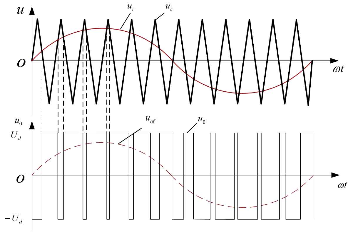
In a unipolar PWM solar inverter, the variation of the triangular carrier wave does not occur in both polarities at the same time, but only in one polarity. As a result, the resulting PWM pulse sequence is only unipolar within half a cycle, and only one switching device on the same bridge arm of the solar inverter changes with the PWM pulse sequence. As shown in Figure 2:
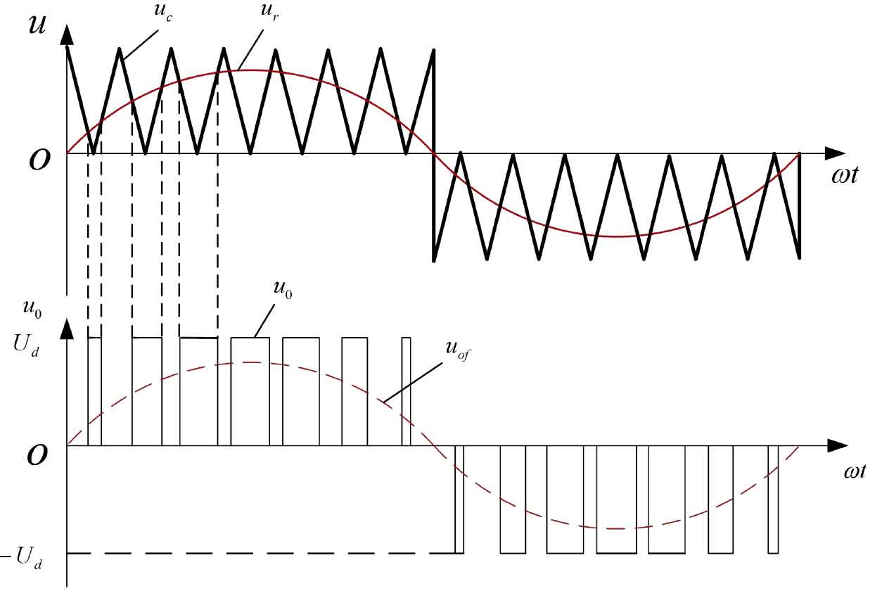
The carrier signal of the PWM solar inverter with bipolar working mode adopts bipolar triangular wave signal, and the two switching devices on and off the same bridge arm of the solar inverter complement each other alternately. The output voltage polarity is bipolar within the half cycle of the sine wave. As shown in Figure 3: