
The solar photovoltaic power generation system adopts a new type of power generation technology that has emerged in today’s society, specifically manifested as the use of solar panels to absorb sunlight energy and convert it into usable electrical energy. Although the development time and application of solar photovoltaic power generation system, a new technology, is not very long nowadays, it will become a key development industry in China due to its long service life, environmental protection, high reliability, and the increasing emphasis on clean energy development by the country.
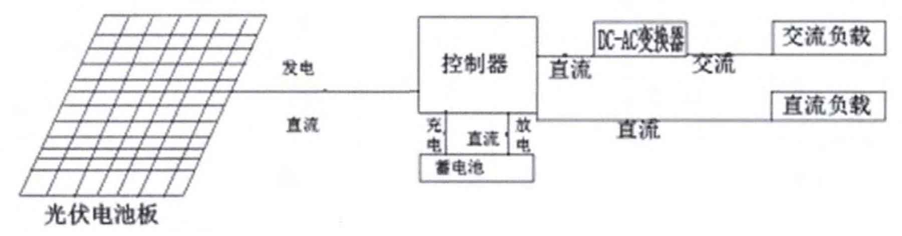
A common solar photovoltaic power generation system can be composed of DC-AC converters, batteries, photovoltaic panels, controllers, and loads through close connections. The relationship between them is shown in Figure 1.
DC-AC converter: It is another core part of the above components, in addition to solar photovoltaic panels. Its purpose is to achieve the conversion of current DC-AC through integrated bridge stacks in the case of upper and lower level docking, closely related to the load.
Battery: The function of a battery in the system is not significantly different from that of a regular battery, and its main purpose is to store direct current for use with the next load.
Solar photovoltaic panel: It is an important component of the solar photovoltaic power generation circuit, and its key use is to achieve the transition from light energy to electrical energy for use in the next level.
Controller: Its main purpose is to stably and efficiently charge and backup batteries under DC load conditions.
Solar energy, as a form of radiant energy, must be converted into electrical energy through an energy converter. This type of energy converter can convert solar energy into light energy, and this type of energy converter is called a solar photovoltaic module; The solar photovoltaic effect is the effect of an electromotive force generated by a certain material after absorbing solar energy. The solar photovoltaic effect is the effect of an electromotive force generated by a certain material after absorbing solar energy. Whether in gas, liquid, or liquid, solar photovoltaic modules can convert light energy into electrical energy based on the solar photovoltaic effect, especially in solid semiconductors with the highest conversion rate.
Focusing on three-phase grid connected inverters, the structure, main circuit working state, simulation model, maximum power point tracking (MPPT) control algorithm, and islanding detection calculation of solar photovoltaic grid connected inverter systems are studied. The two core parts of the solar photovoltaic grid connected power generation system are the maximum power point tracking (MPPT) control of the solar panel and the solar photovoltaic grid connected inverter control. The characteristics of the system are as follows:
1) The main control chip of the system adopts a DSP high-speed computing chip, which has good real-time performance and ensures the quality of the inverter’s output power;
2) The control strategy of the main control circuit is implemented through software, with fewer peripheral circuits, which is convenient for future upgrades;
3) Develop supporting monitoring systems to ensure the stability of the entire solar photovoltaic power generation inverter system;
4) Perfect protection functions: overvoltage protection, short circuit protection, island protection, overheating protection, overload protection;
5) Convenient power expansion. When the current solar photovoltaic power generation does not meet the household power supply needs, solar photovoltaic panels, inverter components, and related drive circuits can be added to complete the expansion. The new expansion part shares a main control circuit board with the original system, greatly saving expansion costs.
1. System design
The circuit part of the system uses DSP as the main control chip, mainly responsible for the operation of complex control algorithms for inverters, MPPT algorithms, and island detection. In the world photovoltaic market, there are quite a few classic MPPT algorithms for solar photovoltaic cells, such as mountain climbing method (P&O), conductivity increment method (I NC), constant voltage method (CVT), and database based maximum power tracking method. The main control circuit of the system mainly includes DSP main control unit, signal sampling and conditioning circuit, inverter main circuit, low-pass filter, drive protection circuit, etc. The system uses ARM as an auxiliary control chip, which is connected to DSP through a serial port. It is mainly responsible for monitoring, displaying and storing relevant information of the entire system, communicating with the upper computer, etc. The auxiliary control expansion functions of the system include buttons, LCD display, communication interface, light intensity and temperature/humidity detection circuit in the inverter environment, real-time clock, fault storage circuit, etc.
2. Three phase full bridge inverter
Inverter power sources are widely used in civil, defense technology, aerospace and other fields, so higher and better redundancy, capacity, and stability are needed to meet the above industries. Connecting multiple modules in parallel before running can effectively improve the overall capacity. When the capacity is fixed, low-power electronic components can be used through parallel connection, which can achieve the effect of simple capacity expansion and short design time. In addition, the integration of hot swapping technology will greatly improve the overall stability and redundancy. In addition, the switching current of the full wave rectifier bridge DC to AC transformer is only half of that of the half wave rectifier bridge DC to AC transformer, so it is widely used in high power consumption situations. In the full wave rectifier bridge DC to AC transformer, there will be an AC transformer at the output port to ensure safe electrical isolation and good output voltage value in the output and input.
A three-phase inverter parallel topology based on fiber optic ring network is proposed here.
2.1 Structure of three-phase full bridge inverter
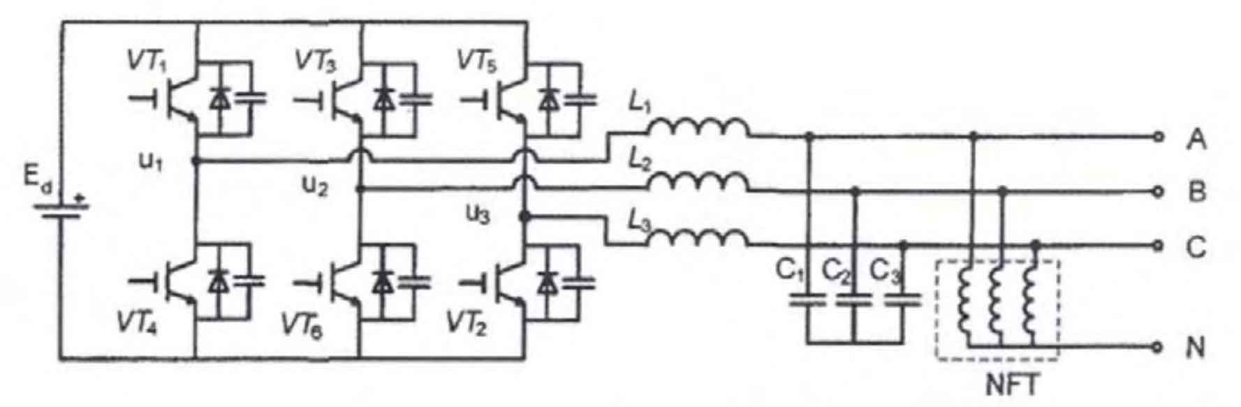
The inverter design adopts the structure shown in Figure 2, consisting of a main circuit composed of an inductor capacitor filter, a three-phase full wave rectifier bridge converter, and a main line capacitor. All insulated gate bipolar transistor modules have anti parallel diodes; C. L is the AC filtering capacitor and inductance; NFT is the three-phase output phase voltage vector, Ed is the stranded bus voltage value, Uin=[u1u2u3] T is the three-phase inverter bridge wall voltage vector.
2.2 Work Plan
The scheme of using no output isolation transformer reduces the volume and weight of the inverter, and improves the power density of the three-phase inverter. However, the output terminals of each module are directly connected in parallel, so it is required to have a significant constraint on the circulating current, because the overall equivalent impedance of the loop is relatively small, and it is easy to generate large circulating currents no matter how small the voltage deviation is.
This DC to AC transformer only has one central control device, with Digital Signal Processing as the central controller chip. Its main purpose is to adjust the current and voltage of each axis, handle errors, and adjust spatial measurements. Each module contains a lower level control device, which uses the Field Programmable Gate Array as the control chip to activate insulated gate bipolar transistors, collect various basic information, and communicate. The central controller receives parameters such as three-phase current and voltage processed by the lower controller. It implements a closed-loop control algorithm to make the current and voltage parameters more variable on both axes. After undergoing steps such as dual loop linear modulation, the space vector is controlled by Pulse Width Modulation to generate a duty cycle parameter, which is transmitted to each lower controller through parameter communication network switching. The start pulse signal is compared and generated within the lower controller. By using the command to search for physical addresses, each lower level controller only obtains parameters associated with itself, while the remaining parameters are sent to other intersections and wait for the stimulation signal of the synchronous ring network. After the lower level controller receives the signal from the synchronous ring network, through a special control scheme, each module synchronously executes control commands and takes action. Under the above control plan, the action accuracy of each layer of controller in the system is quite accurate.
Because each module has the same level, when running closed-loop calculations, each module is equal in terms of voltage parameters. In terms of current signals, when running control, the inductance current parameters of the middle module are arbitrarily grabbed for control, and the other modules issue equal duty cycle parameters. The other modules will track the module themselves. Because it is arbitrary to grab the inductance current, if one of the modules produces an error, it will randomly grab another inductance current parameter from the other modules for control, which provides a certain guarantee for stability. If the remaining modules also generate errors during use, the corresponding contactor components of the module will be disconnected to block the startup pulse of the module. The corresponding lower controller will no longer generate startup pulses and only forward the parameters of the other modules.
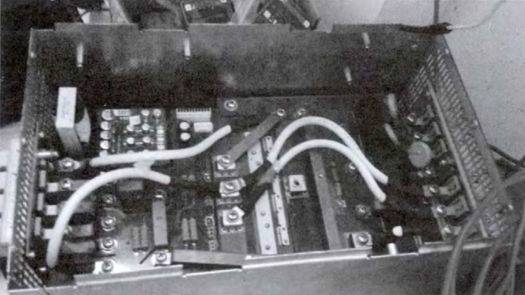
After production, the inverter shown in Figure 3 is HZ-1 type.
2.3 Application of HZ-1 inverter in elevators
The HZ-1 inverter is used for the HGP-1050-CO150 elevator, and the test results show that the performance is better than the indicators specified in the contract. Through testing by Guangdong Special Equipment Testing Institute, the following summary is formed:
1) By using the method of simulating the global working situation testing, the energy-saving data of the elevator with energy feedback units that are relatively non-existent under various load values are as follows:
41.19% at rated load, 22.30% at 75% rated load, -6.24% at 50% rated load, 14.91% at 40% rated load, 36.11% at 25% rated load, and 44.85% at no load.
The comprehensive power saving rate is 30.24%.
2) When the elevator operates at an average speed, the minimum power factor of the energy feedback device is 99.83%.
3) When the elevator operates at an average speed, the maximum current total harmonic distortion value THDi of the energy feedback device is 0.040 1.
4) The energy transfer efficiency of the energy feedback device is 96.1%.
After successful debugging, it is used for the inverter system of solar photovoltaic power generation as shown in Figure 4.

3. Grid connection of solar photovoltaic power generation
Solar photovoltaic power grid connection refers to the direct current generated by solar modules being converted into AC power that meets the requirements of the municipal power grid through grid connected inverters and directly connected to the public power grid. The preliminary DC power supply generated by various component combinations is smoothly converted into a current that meets the requirements of the power grid through the DC to AC transformer in the components and integrated into the power grid.
One type of approach for grid connection is grid operation that does not involve charging, and the other type is grid generation that involves charging. The system without charging does not have scheduling function and emergency backup power, but when it is charged, it has the effect of emergency backup power.
The main element of its grid connection is that the phase and frequency of the current emitted by the DC to AC transformer are equal to the phase and frequency of the grid voltage. In order to meet this requirement, the main link of this grid connected power generation technology is the grid connected DC to AC transformer. The optimization of its performance is crucial for improving overall stability, improving overall lifespan, and reducing related costs.
4. Conclusion
Based on the application of HZ-1 inverter in elevators, it can be seen that the most core part of the entire technical research is to invert DC voltage back to AC voltage. The entire system needs to be supported by a reliable Digital Signal Processing main control chip, supplemented by efficient control strategies. The upper controller and lower controller are interconnected to provide data exchange, providing short circuit protection, overvoltage protection, overload protection for the entire system Overheat protection, etc.