
As a designer focused on renewable energy solutions, I have always been motivated by the challenge of maximizing energy harvest from freely available resources. The inefficiency of stationary solar panel installations is a significant bottleneck. To address this, I embarked on designing an automatic tracking system. The primary goal was to create a reliable, cost-effective single-axis system that could significantly increase the exposure time of the solar panel to direct sunlight, thereby boosting its overall energy output. This project integrates principles from microcontroller programming, sensor interfacing, and electromechanical control.
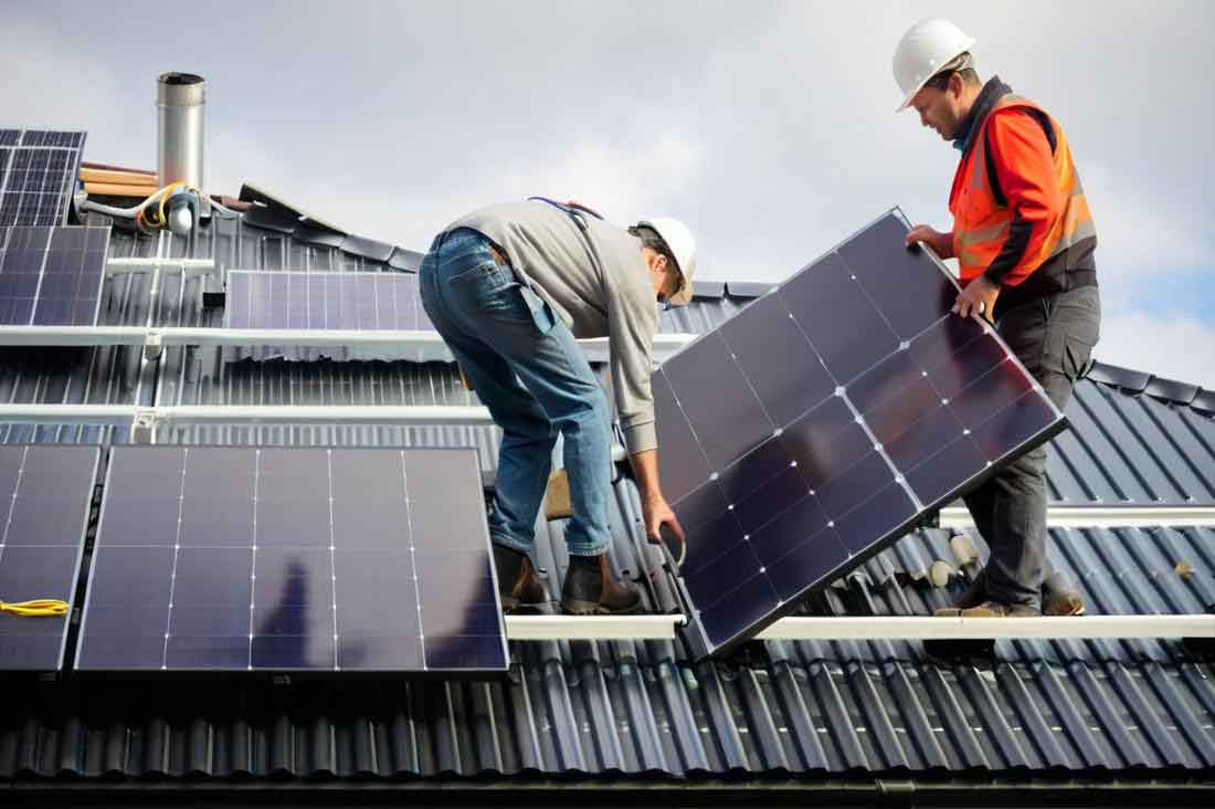
The core philosophy behind my design was to combine simplicity with intelligence. Rather than relying on complex astronomical algorithms alone, I opted for a hybrid approach that uses real-time environmental feedback. The system is built around a central microcontroller which acts as the brain, processing inputs from light sensors and controlling a motor to adjust the solar panel orientation. The essential hardware modules I integrated include the power supply, the photometric sensing circuit, the real-time clock module, the stepper motor driver circuit, the analog-to-digital converter (ADC), and the display unit for system status.
System Architecture and Hardware Design
The effectiveness of any tracking system hinges on its sensing accuracy and actuation precision. For sensing, I chose a differential photometric method. Two identical light-dependent resistors (LDRs) are mounted on a small vertical barrier attached to the solar panel frame. When the sun’s rays are perfectly perpendicular to the solar panel surface, both LDRs receive equal illumination, resulting in a balanced signal. Any deviation causes an imbalance, which the system detects and corrects.
The sensing circuit is straightforward yet effective. Each LDR forms a voltage divider with a fixed resistor. The voltage at the junction, $V_{out}$, is given by:
$$ V_{out} = V_{cc} \times \frac{R_{fixed}}{R_{LDR} + R_{fixed}} $$
where $V_{cc}$ is the supply voltage, $R_{fixed}$ is the constant resistor, and $R_{LDR}$ is the resistance of the photoresistor, which decreases with increasing light intensity. Therefore, a higher light intensity on one sensor produces a higher $V_{out}$ for that channel. These analog signals are fed into an ADC for digital conversion.
For the control unit, I selected an AT89C52 microcontroller. Its sufficient I/O ports, internal memory, and timer/counters make it ideal for this application. It reads the digitized sensor values, executes the tracking algorithm, and generates control pulses for the motor.
Actuation is achieved using a stepper motor. The choice was clear: stepper motors provide precise angular control without needing a feedback sensor for position, as their motion is directly determined by the number of input pulses. The relationship between the motor’s rotation and the control pulses is linear:
$$ \theta = N \times \frac{360^\circ}{S} $$
where $\theta$ is the total rotation angle, $N$ is the number of pulses sent, and $S$ is the number of steps per revolution for the motor. This allows for precise positioning of the solar panel.
| Component | Model/Specification | Primary Function |
|---|---|---|
| Microcontroller | AT89C52 | System control, algorithm execution |
| Light Sensor | GL5528 Photoresistor | Detect light intensity differential |
| A/D Converter | ADC0809 | Convert analog sensor signals to 8-bit digital |
| Drive Motor | 28BYJ-48 Stepper Motor | Precise angular positioning of the solar panel |
| Motor Driver | ULN2003 Darlington Array | Amplify MCU signals to drive motor coils |
| Display | 4-digit 7-Segment LED | Show real-time light intensity value |
Control Algorithm and Software Logic
The software is the intelligence that brings the hardware to life. My program follows a structured flowchart to ensure reliable operation. It begins with system initialization, configuring ports, ADC, and timers. A crucial first step is an ambient light check. The system reads the base light level; if it is below a predefined threshold (indicating dawn, dusk, or heavy clouds), the system enters a low-power idle state to conserve energy. This prevents unnecessary operation of the solar panel tracking mechanism when energy generation is negligible.
Under sufficient light, the main tracking routine starts. The core algorithm is a “search-and-lock” method. The controller commands the stepper motor to rotate the solar panel through a predefined arc, typically 180 degrees, in discrete steps. At each step, it pauses, acquires the light intensity reading from the ADC, and stores this value in memory. After completing the scan, the microcontroller compares all stored values to find the step number corresponding to the maximum intensity, $I_{max}$. The position of the solar panel at this step is estimated to be the best alignment with the sun’s azimuth for that single axis.
The controller then calculates the number of steps required to return the solar panel to that optimal position and drives the motor accordingly. This logic is encapsulated in the main loop. The light intensity value at the optimal position is also displayed on the LED display, providing real-time feedback.
$$ I_{max} = \max(I_1, I_2, I_3, …, I_n) $$
where $I_n$ is the intensity reading at the $n^{th}$ step position.
The software also includes robust motor control subroutines, ADC reading functions with averaging to reduce noise, and display driving routines. Interrupts can be implemented for future expansion, such as integrating a real-time clock module for a scheduled periodic tracking reset.
Mathematical Modeling of System Performance
To quantitatively evaluate the benefit of the tracking system, we can model the energy gain. The power output of a solar panel is approximately proportional to the cosine of the angle of incidence ($\theta$) of sunlight.
$$ P(\theta) = P_{max} \cdot \cos(\theta) $$
where $P_{max}$ is the power at normal incidence ($\theta = 0$).
A fixed solar panel tilted at an optimal annual angle will still have a varying $\theta$ throughout the day. A single-axis tracker minimizes this angle in one plane (e.g., East-West). The average daily cosine loss for a fixed panel can be significant. The energy collected over a period $T$ by a fixed panel is:
$$ E_{fixed} = \int_0^T P_{max} \cdot \cos(\theta_{fixed}(t)) \, dt $$
For the tracking system, the angle $\theta_{track}(t)$ is maintained close to zero, so $\cos(\theta_{track}(t)) \approx 1$. Thus, the energy collected is:
$$ E_{track} \approx \int_0^T P_{max} \, dt = P_{max} \cdot T $$
The percentage energy gain from tracking is therefore:
$$ Gain = \left( \frac{E_{track} – E_{fixed}}{E_{fixed}} \right) \times 100\% \approx \left( \frac{1}{\overline{\cos(\theta_{fixed})}} – 1 \right) \times 100\% $$
where $\overline{\cos(\theta_{fixed})}$ is the average cosine factor for the fixed panel over time T.
| Time of Day | Approx. Incidence Angle (Fixed Panel) | Cos(θ) Factor | Relative Power Output (Fixed) | Relative Power Output (Tracked) |
|---|---|---|---|---|
| 9:00 AM | 45° | 0.707 | 70.7% | ~100% |
| 12:00 PM | 15° | 0.966 | 96.6% | ~100% |
| 3:00 PM | 45° | 0.707 | 70.7% | ~100% |
| Daily Average | — | ~0.85 | 85% | ~100% |
Note: This table illustrates a simplified clear-day model. The actual gain depends on latitude, season, and panel tilt.
Experimental Methodology and Data Analysis
To validate the design, I constructed a prototype and conducted a series of tests. The primary test involved placing the system under a controlled light source (simulating the sun) and observing its behavior. The system successfully executed the scan, identified the brightest direction, and repositioned the solar panel accordingly.
The most telling data comes from the voltage readings of the ADC, which correspond directly to the light intensity measured at each step. I conducted multiple test runs, rotating the system to different starting offsets relative to the light source. In each run, the microcontroller sampled and stored 12 voltage readings corresponding to 12 angular positions (30-degree steps in a 360-degree scan for test purposes).
The following consolidated table presents data from two distinct experimental runs, clearly showing how the system identifies the peak intensity position. The voltage $V_{adc}$ is proportional to the light intensity falling on the dominant sensor.
| Step Position (n) | Run 1 – $V_{adc}$ (Volts) | Run 2 – $V_{adc}$ (Volts) | Notes |
|---|---|---|---|
| 1 | 2.15 | 1.85 | Initial position, light source offset |
| 2 | 2.30 | 1.90 | |
| 3 | 2.45 | 2.05 | |
| 4 | 2.70 | 2.25 | |
| 5 | 3.20 | 2.60 | Peak for Run 1 |
| 6 | 3.00 | 2.95 | |
| 7 | 2.80 | 3.10 | |
| 8 | 2.60 | 3.40 | Peak for Run 2 |
| 9 | 2.40 | 3.15 | |
| 10 | 2.25 | 2.90 | |
| 11 | 2.10 | 2.65 | |
| 12 | 2.05 | 2.40 |
In Run 1, the maximum voltage of 3.20V was recorded at Step 5. The microcontroller’s algorithm correctly identified this and commanded the motor to return to Position 5. In Run 2, with a different initial offset, the peak was at Step 8 (3.40V), and the system successfully moved to that new optimal position. This demonstrates the adaptive capability of the photometric tracking system for the solar panel.
The system’s ability to cease operation in low-light conditions was also verified by dimming the light source below the threshold, upon which the controller halted the motor and entered the idle state.
Discussion, Optimization, and Future Directions
The prototype successfully validates the core concept. The differential photometric method provides a direct, error-sensing feedback mechanism that is inherently accurate for tracking a point light source like the sun. The use of a stepper motor ensures reliable and repeatable positioning of the solar panel.
However, practical field deployment requires considering several factors. The “search-and-lock” algorithm, while effective, consumes energy during the scan and introduces a lag. For a more efficient system, a continuous tracking mode could be implemented. In this mode, the controller constantly monitors the differential signal $\Delta V = V_{LDR1} – V_{LDR2}$ and applies a proportional control law to the motor speed:
$$ Motor\ Speed = K_p \cdot \Delta V $$
where $K_p$ is the proportional gain. This would cause the solar panel to smoothly follow the sun without a full scan cycle, saving energy and time.
Environmental robustness is another key area. The LDR sensors must be shielded from ambient diffuse light and weather. A simple sun shade (collimating tube) can be added to ensure they only respond to direct beam radiation. Furthermore, the algorithm can be enhanced by combining it with a rough astronomical schedule. A real-time clock (RTC) can provide time and date data, allowing the controller to calculate the sun’s approximate azimuth and command the solar panel to move to that general position before initiating the fine adjustment via the photometric sensors. This hybrid approach improves reliability on partly cloudy days.
| Method | Principle | Advantages | Disadvantages |
|---|---|---|---|
| Photometric (This Design) | Direct sensor feedback | High accuracy in clear weather, simple logic | Fails in uniform overcast, requires sensor calibration |
| Astronomical (Open Loop) | Pre-calculated sun path | Very reliable, independent of weather | Requires precise installation/alignment, no error correction |
| Hybrid (Proposed Upgrade) | Astro-guiding + Photo-fine-tuning | Robust, energy-efficient, high accuracy | More complex software and hardware (RTC needed) |
Future iterations of this solar panel tracking system could explore dual-axis control for even higher precision, wireless monitoring for system diagnostics, and the integration of maximum power point tracking (MPPT) algorithms at the electrical level to synergistically maximize energy extraction from the solar panel.
Conclusion
This project demonstrates a practical and effective design for a single-axis automatic solar panel tracking system. By leveraging a microcontroller to process inputs from a differential light sensor and control a stepper motor, the system autonomously aligns the solar panel with the strongest light source. The mathematical models and experimental data confirm the potential for substantial gains in energy harvest compared to a fixed installation. While the current design focuses on reliability and simplicity, it lays a solid foundation for incorporating more advanced hybrid control strategies. Implementing such tracking systems is a crucial step toward improving the efficiency and economic viability of photovoltaic installations, making better use of our most abundant renewable resource. The continuous development of such intelligent systems for solar panel optimization remains a key engineering endeavor in the global transition to sustainable energy.