
The large-scale integration of distributed generation, particularly solar photovoltaic (PV) systems, into modern power distribution networks marks a significant shift from traditional, passive grid structures. This transition, driven by global decarbonization goals and the pursuit of clean energy, fundamentally alters power flow patterns and operational dynamics. While offering substantial environmental benefits, the proliferation of distributed PV poses considerable challenges to power supply security, power quality, and the overall stability and reliability of the grid. The conventional distribution network, originally designed for unidirectional power flow from centralized generation to distributed loads, is now required to accommodate bidirectional flows and manage sources with intermittent and variable output. This paradigm shift necessitates a re-evaluation of grid management strategies. A critical aspect of this challenge lies in mitigating the adverse impacts on voltage profiles and power quality, notably voltage rise at feeder ends and harmonic pollution, which are often exacerbated when local generation exceeds local consumption. Addressing these issues is paramount to unlocking the full potential of distributed solar energy while ensuring a safe, reliable, and high-quality power supply for all connected users.
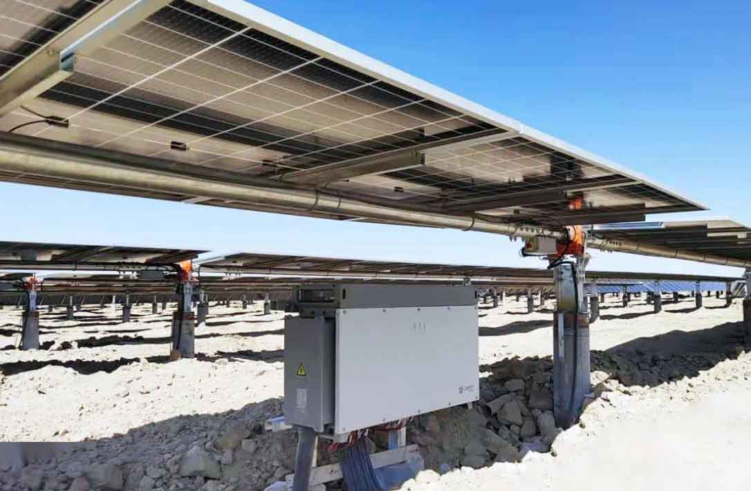
The core component enabling grid integration of solar energy is the solar inverter. Beyond its primary function of converting direct current (DC) from PV panels into grid-compliant alternating current (AC), the modern solar inverter possesses inherent capabilities for reactive power control. Traditionally, grid-connected inverters operate at unity power factor, injecting only active power (P). However, by controlling the phase and magnitude of its output voltage relative to the grid voltage, a solar inverter can dynamically absorb or generate reactive power (Q). This capability transforms the inverter from a mere power source into a dispatchable grid-supporting asset. This article explores in depth the strategies and methodologies for leveraging solar inverter reactive power capabilities to participate actively in grid voltage control, thereby addressing the technical challenges associated with high-penetration distributed PV integration.
The impact of distributed PV on the grid, particularly on voltage levels, can be understood through basic power flow principles. Consider a simplified representation of a distribution feeder section with an integrated solar inverter. The inverter is often modeled as a current source interfaced with the grid through coupling impedance. The key relationship governing the voltage at the Point of Common Coupling (PCC) is given by the voltage drop equation. For a single-phase representation, the voltage rise at the inverter terminal relative to the source can be approximated as:
$$\Delta V \approx \frac{R \cdot P + X \cdot Q}{V_{grid}}$$
where $R$ and $X$ are the resistance and reactance of the line between the source and the PCC, $P$ and $Q$ are the active and reactive power outputs of the solar inverter, and $V_{grid}$ is the nominal grid voltage. Under normal unity power factor operation ($Q=0$), the solar inverter injects active power $P$, which can reverse the traditional voltage drop along the feeder and cause a voltage rise ($\Delta V > 0$), especially pronounced at the far end of a long or high-impedance feeder. This overvoltage scenario is prevalent during periods of high solar insolation and low local load, such as midday on sunny days.
The solar inverter’s ability to regulate reactive power offers a direct solution to this voltage rise problem. By examining the inverter’s operating phasor diagram, the control mechanism becomes clear. The inverter’s AC-side output voltage $V_{inv}$ is controlled by power electronics relative to the grid voltage $V_g$. The current $I_L$ flowing through the coupling inductor is determined by the difference between these voltages. The fundamental relationship is:
$$\overrightarrow{I_L} = \frac{\overrightarrow{V_{inv}} – \overrightarrow{V_g}}{jX_L}$$
where $X_L$ is the inductive reactance of the coupling filter. The complex power injected into the grid is $S = P + jQ = \overrightarrow{V_g} \cdot \overrightarrow{I_L}^*$. By manipulating the magnitude and phase angle $\delta$ of $V_{inv}$, the inverter can control both $P$ and $Q$ independently within its apparent power rating $S_{max}$. The operational limits are defined by the inverter’s capability curve, often described by:
$$P^2 + Q^2 \leq S_{max}^2$$
When the inverter operates at its maximum active power point ($P = P_{max}$), the remaining capacity for reactive power compensation is $Q_{available} = \pm \sqrt{S_{max}^2 – P_{max}^2}$. This highlights a key trade-off: providing reactive power support may require curtailing active power output if the inverter is operating at its apparent power limit. Advanced control strategies can dynamically manage this trade-off based on grid conditions.
There are two primary modes for a solar inverter to engage in voltage support: 1) **Voltage Regulation Mode (Q-V Control)**: The inverter adjusts its reactive power output based on the local PCC voltage measurement. A typical droop characteristic is employed:
$$Q = Q_{max} \cdot \frac{V_{ref} – V_{pcc}}{V_{deadband}} \quad \text{for} \quad |V_{ref} – V_{pcc}| > V_{deadband}$$
where $V_{ref}$ is the reference voltage, $V_{pcc}$ is the measured voltage, $V_{deadband}$ is a permissible voltage deviation band where no action is taken, and $Q_{max}$ is the maximum available reactive power (capability limited). If $V_{pcc}$ is above the upper threshold, the inverter consumes reactive power (acts inductively, negative Q), drawing capacitive current to lower the voltage. Conversely, if $V_{pcc}$ is below the lower threshold, it generates reactive power (acts capacitively, positive Q) to support the voltage. 2) **Power Factor Control Mode (cosφ Control)**: The inverter maintains a preset power factor, either fixed or variable based on a schedule (e.g., time of day or active power level). The reactive power setpoint is derived from $Q = P \cdot \tan(\arccos(\phi))$.
The effectiveness of solar inverter-based voltage control depends on several factors, including network topology, R/X ratio, the penetration level of solar inverters, and the coordination of multiple units. Uncoordinated local control by individual solar inverters can lead to conflicts or instability. Therefore, hierarchical or coordinated control architectures are proposed. In a decentralized approach, solar inverters use only local measurements. In a centralized or distributed control scheme, a central controller (e.g., at a substation or district level) calculates optimal setpoints for each solar inverter based on system-wide measurements and objectives, communicating these setpoints via a communication network. This enables optimal Volt/VAr control across the feeder, minimizing losses and preventing voltage violations while maximizing solar energy utilization.
Beyond steady-state voltage issues, solar inverters, as power electronic interfaces, are also sources of harmonic currents. High-frequency switching generates harmonics that can pollute the grid, potentially interfering with sensitive equipment and increasing losses. While grid codes mandate limits on total harmonic distortion (THD), additional filtering may be necessary, especially in areas with high concentrations of solar inverters. The interaction between the inverter’s harmonic emission and the grid impedance can lead to resonance issues. Therefore, the design of the solar inverter’s output filter (typically an L or LCL filter) is critical not only for switching ripple attenuation but also for shaping the harmonic impedance. Some advanced solar inverters incorporate active harmonic filtering functions, using their control bandwidth to inject compensating currents that cancel out specific harmonic components present on the grid, thereby improving the overall power quality at the PCC.
To fully harness the reactive power capability of the solar inverter without compromising active power generation during most operating hours, or to provide enhanced compensation beyond the inverter’s own capacity, external solutions can be deployed. One innovative approach involves a controllable series compensation device placed in series with the solar inverter’s output. This device, featuring a wide-bandwidth reactive inductor, can be switched based on the detection of overvoltage conditions. It provides inductive reactive power absorption directly, effectively mitigating voltage rise without requiring modification to the solar inverter’s internal control settings. This external compensator can be designed with advanced magnetic composite materials to achieve low losses across a wide frequency range, offering the dual benefit of reactive power absorption and suppression of high-frequency harmonic currents from the solar inverter. This solution is particularly valuable for retrofitting existing solar installations where inverter firmware may not be easily updatable for advanced grid support functions.
The performance and characteristics of this external solar inverter filtering and reactive power compensation device can be compared with traditional solutions like the Static Var Generator (SVG), as summarized in the table below.
| Parameter | Traditional SVG Compensator | Solar Inverter Filtering & Reactive Compensation Device |
|---|---|---|
| Reliability | Requires dedicated protection schemes and complex power electronics. | Simpler passive/semi-active design; often requires fewer protective devices. |
| Standby & Operational Losses | Has inherent no-load losses and switching losses during reactive power exchange. | Losses are primarily conduction losses; minimal to zero loss during night-time or inverter-off periods. |
| Installation & Footprint | Typically requires significant cabinet space, cooling, and has high environmental (EMI) requirements. | Compact design; can be integrated near the inverter with less stringent environmental constraints. |
| Cost & Overload Capability | Higher initial cost for equivalent rating; usually designed for 1.1-1.2 pu short-term overload. | Potentially lower cost for specific applications; magnetic components can often handle 1.5-1.6 pu long-term overload. |
| Primary Function Integration | Dedicated reactive power compensation device. | Combines harmonic filtering and reactive compensation specifically tailored for solar inverter outputs. |
Another significant power quality concern is the propagation of high-frequency noise and zero-sequence harmonics through grounding paths. The high-frequency switching of a solar inverter can induce common-mode currents that flow through cable shields and grounding conductors, potentially causing electromagnetic interference (EMI) with sensitive communication systems and protective relays in the grid. To mitigate this, specialized grounding harmonic suppression techniques are employed. One effective method involves installing high-permeability magnetic cores around the grounding conductors or inverter output cables. These cores, made from materials like nanocrystalline or high-permeability silicon steel, present a high impedance to high-frequency common-mode currents, effectively attenuating them before they enter the grounding grid. The impedance introduced by such a suppressor can be modeled as $Z_{sup}(f) = j 2\pi f L_{sup}(f)$, where $L_{sup}(f)$ is the frequency-dependent inductance of the core. By reducing the amplitude and slew rate of these high-frequency currents, the risk of interference with secondary equipment is substantially diminished, enhancing the overall electromagnetic compatibility of the solar installation.
Implementing reactive power and voltage control through solar inverters necessitates careful consideration of stability. The control loops governing the solar inverter’s current, power, and voltage must be designed to ensure robust performance under various grid conditions, including weak grids with high impedance. The interaction between the inverter’s control dynamics and the grid impedance can lead to subsynchronous oscillations or instability. Stability analysis often involves examining the inverter output impedance $Z_o(s)$ and the grid impedance $Z_g(s)$. A common criterion derived from the Middlebrook and Nyquist stability theorems is to ensure that the ratio of the grid impedance to the inverter output impedance satisfies certain conditions across all frequencies. The design of the inverter’s current controller (typically PI or PR in the synchronous reference frame) and the phase-locked loop (PLL) is critical. A well-designed PLL accurately tracks the grid voltage phase under distorted or unbalanced conditions, ensuring the correct orientation of the dq-axis for independent P and Q control. The reactive power control loop itself must have appropriate bandwidth and gain to respond effectively to voltage deviations without causing oscillations.
The future development of solar inverter technology points towards even greater grid-support functionality, often referred to as “grid-forming” capabilities. While most existing solar inverters operate in “grid-following” mode, synchronizing to the grid voltage, grid-forming inverters can autonomously establish and regulate the grid voltage and frequency. This is achieved through control algorithms that emulate the inertia and damping characteristics of synchronous generators, using equations like:
$$\frac{d\theta}{dt} = \omega_0 + K_p (P_{ref} – P)$$
$$V_{mag} = V_0 + K_q (Q_{ref} – Q)$$
where $\theta$ and $V_{mag}$ are the inverter’s output voltage angle and magnitude, $\omega_0$ is the nominal frequency, and $K_p$, $K_q$ are droop coefficients. This capability is essential for the stability of future power grids with very high penetrations of inverter-based resources like solar and wind, where traditional synchronous generation is minimal. The solar inverter thus evolves from a passive generator into an active grid-forming unit that can provide essential system services such as frequency response, black-start capability, and robust operation in islanded microgrids.
In conclusion, the integration of solar inverters as active participants in grid voltage and reactive power control represents a paradigm shift in distribution network management. By leveraging the inherent power electronics control flexibility of the solar inverter, the adverse impacts of distributed PV on voltage profiles and power quality can be effectively mitigated. Strategies range from local Q-V droop control and power factor regulation to coordinated system-wide optimization and the use of external complementary devices. These approaches not only solve technical problems like overvoltage and harmonic pollution but also enhance the utility and value of distributed solar assets. As grid codes worldwide increasingly mandate such capabilities, the modern solar inverter is poised to become a cornerstone of a resilient, flexible, and high-quality smart grid, facilitating the secure and large-scale integration of renewable energy sources. The continued advancement in solar inverter control algorithms, stability analysis, and grid-support functions will be critical in realizing the full potential of a decarbonized energy system.