
In the face of global challenges posed by fossil fuel scarcity and environmental degradation, the transition towards sustainable energy sources has become imperative. The era of inexpensive oil is conclusively over. Photovoltaic (PV) power generation stands out as a pivotal technology in this transition. However, a PV system is not a standard piece of equipment; its configuration must be meticulously tailored based on load requirements, local meteorological conditions, and geographical specifics. To reduce the levelized cost of electricity and maximize reliability, an optimized design is essential. This ensures the economic viability and dependable operation of the installation over its long lifespan. In this article, I will walk through the comprehensive design process of a smart grid-connected solar system, using a 45 kWp case study as a reference. I will detail the component selection, system architecture, and perform a thorough analysis of its projected energy yield, financial return, and environmental benefits over a 25-year period.
1. Foundational Design Principles for a Grid-Connected Solar System
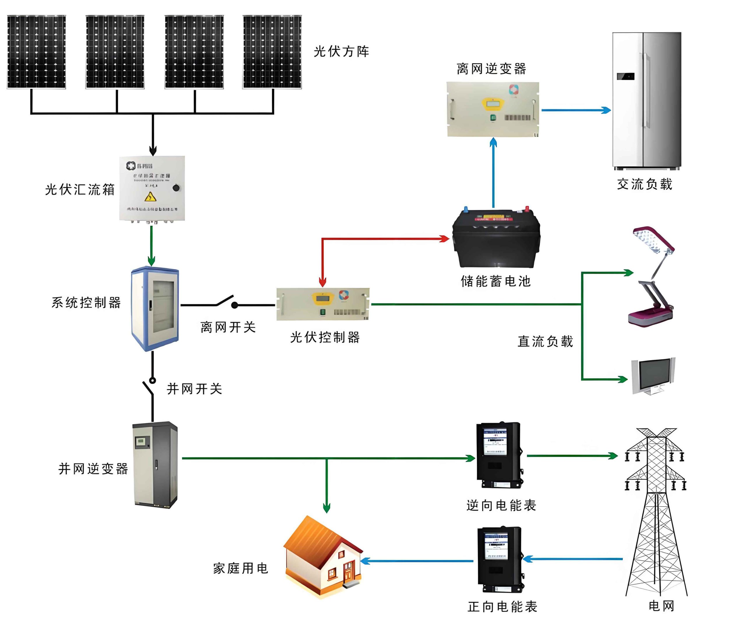
The core objective of designing a grid-connected solar system is to achieve an efficient, safe, and reliable interface between the photovoltaic array and the public electricity grid. The primary components include the PV modules, mounting structures, DC cabling, protection devices, combiner boxes, inverters, AC distribution units, and monitoring systems. The design must account for factors like maximum power point tracking (MPPT) voltage windows, string sizing, thermal derating, and grid compliance standards.
The overarching principle is to match the DC characteristics of the PV array to the input requirements of the inverter, while ensuring all electrical protections are in place. A typical energy flow is as follows: when the solar system production exceeds the on-site load demand, the surplus energy is fed back into the utility grid. Conversely, when generation is insufficient, power is drawn from the grid to meet the load. This seamless interaction necessitates intelligent inverters and proper grid interconnection protocols.
2. Component Selection and System Architecture Design
The efficacy of any solar system hinges on the careful selection and integration of its components. For our 45 kWp case, every element was chosen based on performance, compatibility, and long-term durability.
2.1 Photovoltaic Module Selection and Array Configuration
We selected 180 units of 250 Wp polycrystalline silicon modules. Key electrical parameters at Standard Test Conditions (STC) are:
$$P_{max} = 250W,\quad V_{mp} = 29.5V,\quad V_{oc} = 37V,\quad I_{mp} = 8.47A$$
The inverter’s MPPT voltage range is 450 V to 820 V. To operate within this optimal window, we configure strings of 20 modules in series:
$$V_{string-mp} = 20 \times 29.5V = 590V$$
$$V_{string-oc} = 20 \times 37V = 740V$$
Both values are well within the inverter’s operational limits, even considering temperature-induced voltage variations.
With a total of 180 modules, we have 9 identical strings:
$$N_{strings} = \frac{180 \text{ modules}}{20 \text{ modules/string}} = 9 \text{ strings}$$
These 9 strings will be connected in parallel through combiner boxes. The total installed DC power is:
$$P_{dc} = 180 \times 250W = 45,000W = 45 kWp$$
2.2 Mounting Structure Design for Flat Roof
The mounting structure is a ballasted, non-penetrating system designed for flat roofs. The tilt angle is set to the location’s optimal value for maximizing annual yield. The structure elevates the modules approximately 0.5 meters above the roof surface, allowing for passive cooling and easy access for maintenance. Aisles of 4.5 meters are reserved for safe maintenance access. The structural design ensures a uniform load distribution not exceeding 2.0 kN/m², safeguarding roof integrity.
2.3 DC Side Protection and Combiner Box Design
Two combiner boxes, each with 5 inputs and 1 output, are used to consolidate the 9 string outputs. Each input features a fuse for overcurrent protection and a disconnect means. The boxes are rated IP65 for outdoor durability. Critical protective features inside include:
- Polarity protection (anti-reverse diodes) on each input.
- Surge Protective Devices (SPDs) across DC+ to DC-, DC+ to ground, and DC- to ground.
- String-level current monitoring capability for fault detection and performance analysis.
This design localizes protection and simplifies the wiring from the array to the inverter.
2.4 The Core: Grid-Tie Inverter Selection
The inverter is the brain of the solar system. We selected a 50 kW modular three-phase inverter. Modular design offers significant advantages: it allows for intelligent sleep/wake-up modes, reducing no-load losses and improving part-load efficiency. If irradiation is low, some modules can sleep, avoiding inefficient operation of a single large inverter at light load, thus boosting the overall solar system efficiency. Key parameters are summarized below:
| Parameter | Specification |
|---|---|
| Max. DC Input Power | 55 kW |
| MPPT Voltage Range | 450 – 820 V |
| Rated AC Output Power | 50 kW |
| Max. Efficiency | 96.8% |
| European Efficiency | 96.1% |
| Total Harmonic Distortion (THD) | < 3% |
| Power Factor | > 0.99 (adjustable) |
| Communication | RS485, Ethernet (optional) |
The inverter performs maximum power point tracking (MPPT), DC-to-AC conversion, synchronization with the grid, and provides comprehensive system monitoring data.
2.5 AC Distribution and Grid Connection
The AC output of the inverter is connected to a dedicated AC distribution board. This board houses:
- A three-phase circuit breaker for isolation and protection.
- An energy meter to record the total energy fed into the grid.
- Voltage and current meters for real-time monitoring.
- An AC surge protective device at the point of common coupling.
- Proper grounding terminals.
The solar system connects to the low-voltage three-phase grid (400 VAC, 50 Hz) at this point. The interconnection scheme ensures compliance with local grid codes concerning voltage, frequency, and anti-islanding protection.
2.6 Cabling, Grounding, and Lightning Protection
Proper cabling is crucial for efficiency and safety. DC cables from the array are sized to minimize voltage drop (typically <2%). All cable trays are securely fixed, with cables laid straight and绑扎 at regular intervals. A comprehensive grounding system is installed, with all equipment bonded and connected to an earth rod network achieving a ground resistance of less than 4 Ω. Lightning protection is multi-tiered: SPDs at the combiner boxes (DC side) and at the AC distribution board (AC side), forming a coordinated defense for the entire solar system.
2.7 Monitoring and Control System
A smart monitoring system is integral. Using the inverter’s communication ports (RS485/Ethernet), real-time and historical data is transmitted to a local PC or cloud-based platform. Key monitored parameters include:
- Instantaneous DC/AC power and energy yield.
- String currents and voltages.
- Inverter status and fault logs.
- Environmental data (irradiance, module temperature, ambient temperature, wind speed) from optional meteorological sensors.
This allows for remote performance assessment, early fault detection, and preventive maintenance, maximizing the uptime and yield of the solar system.
3. Performance and Impact Analysis of the 45 kWp Solar System
Following the design, a detailed simulation and analysis are conducted to project the long-term performance and benefits.
3.1 Energy Yield Prediction
The annual energy production is estimated using the following formula:
$$E_{annual} = P_{installed} \times H_{peak} \times 365 \times \eta_{system}$$
Where:
- $P_{installed}$ = 45 kWp
- $H_{peak}$ = Average daily peak sun hours at the location (assumed 4.67 hrs).
- $\eta_{system}$ = Overall system efficiency accounting for inverter loss, wiring loss, soiling, and mismatching (assumed 70% or Performance Ratio of 0.7).
For the first year:
$$E_{year1} = 45 \times 4.67 \times 365 \times 0.7 \approx 53,728 \text{ kWh}$$
PV modules experience a slight power degradation each year, typically 0.7-1.0% initially, stabilizing around 0.5-0.7%. A conservative degradation profile is applied to forecast a 25-year yield.
| Year | Power Relative to Initial (%) | Annual Degradation (%) | Annual Energy Yield (kWh) |
|---|---|---|---|
| 1 | 100.00 | 1.00 | 53,728 |
| 2 | 99.00 | 1.00 | 53,191 |
| 3 | 98.00 | 0.90 | 52,654 |
| 4 | 97.10 | 0.80 | 52,170 |
| 5 | 96.30 | 0.80 | 51,740 |
| … | … | … | … |
| 10 | 92.60 | 0.70 | 49,753 |
| 15 | 89.10 | 0.70 | 47,849 |
| 20 | 85.60 | 0.70 | 45,972 |
| 25 | 82.10 | 0.70 | 44,121 |
| 25-Year Total | ~1,213,500 kWh | ||
| Average Annual | ~48,540 kWh | ||
3.2 Financial Viability Assessment
The financial analysis considers electricity savings and revenue from feed-in tariffs. Assumptions:
- Initial electricity rate: $C_0 = 0.06$ USD/kWh.
- Annual electricity rate escalation: $r = 0.04$ USD/kWh.
- Discount rate (social/opportunity cost): $i = 10\%$.
- System lifetime for analysis: $n = 20$ years (conservative, excluding last 5 years of lower output).
- Annual electricity saved/produced in Year 1: $E = 53,728$ kWh.
The annual savings in Year 1, $A_1$, and the annual increase in savings, $G$, are:
$$A_1 = E \times C_0 = 53,728 \times 0.06 = 3,223.68 \text{ USD}$$
$$G = E \times r = 53,728 \times 0.04 = 2,149.12 \text{ USD}$$
The present value (PV) of the total savings over 20 years is calculated using the formula for the present worth of an increasing gradient series:
$$P = A_1 \left[ \frac{(1+i)^n – 1}{i(1+i)^n} \right] + \frac{G}{i} \left[ \frac{(1+i)^n – 1}{i(1+i)^n} – \frac{n}{(1+i)^n} \right]$$
Substituting the values:
$$P = 3,223.68 \times \left[ \frac{(1+0.1)^{20} – 1}{0.1(1+0.1)^{20}} \right] + \frac{2,149.12}{0.1} \times \left[ \frac{(1+0.1)^{20} – 1}{0.1(1+0.1)^{20}} – \frac{20}{(1+0.1)^{20}} \right]$$
$$P \approx 3,223.68 \times 8.5136 + 21,491.2 \times (8.5136 – 2.9722)$$
$$P \approx 27,440 + 21,491.2 \times 5.5414 \approx 27,440 + 119,073$$
$$P \approx 146,513 \text{ USD}$$
This present value of savings represents a significant financial benefit, which, when compared against the initial capital investment, can determine the payback period and return on investment for the solar system. Additional national or local incentives (e.g., feed-in tariffs, tax credits) would further improve economics. Assuming a total incentive of $0.42/kWh for all produced energy over 25 years, combined with the base electricity value, the total revenue can be substantial.
| Description | Value |
|---|---|
| Total Energy Produced (25 yrs) | ~1,213,500 kWh |
| Revenue @ ($0.06 + $0.42)/kWh | ~582,480 USD |
| Present Value of Savings (20 yrs, 10% discount) | ~146,500 USD |
3.3 Environmental Impact Quantification
The deployment of a renewable solar system directly displaces electricity that would otherwise be generated from fossil fuels. The environmental benefits are calculated using standard emission factors. For this 45 kWp system:
The total CO2 emissions avoided can be calculated as:
$$M_{CO2} = E_{total} \times EF_{CO2}$$
Where $EF_{CO2}$ is the grid emission factor (assume 0.57 kg CO2/kWh for a coal-heavy grid).
Similar calculations are done for other pollutants.
| Emission Type | Emission Factor (kg/kWh) | 25-Year Total Avoided |
|---|---|---|
| Carbon Dioxide (CO2) | 0.57 | ~691,695 kg ≈ 692 tonnes |
| Sulfur Dioxide (SO2) | 0.0028 | ~3,398 kg ≈ 3.4 tonnes |
| Nitrogen Oxides (NOx) | 0.0019 | ~2,305 kg ≈ 2.3 tonnes |
| Particulate Matter (PM) | 0.0004 | ~485 kg ≈ 0.49 tonnes |
| Equivalent Coal Saved* | 0.00034 tonnes/kWh | ~413 tonnes |
*Based on a heat rate and coal energy content.
This tangible reduction in greenhouse gases and air pollutants underscores the significant positive environmental contribution of the grid-connected solar system.
4. Conclusion
The design and implementation of a smart photovoltaic grid-connected system require a holistic approach that balances technical precision, economic rationale, and safety compliance. Through the detailed examination of a 45 kWp case study, we have illustrated the step-by-step process: from component selection and string sizing to the integration of protection, monitoring, and grid interface equipment. The use of modular inverters, comprehensive monitoring, and multi-layer protection exemplifies modern best practices for a robust and intelligent solar system.
The subsequent performance analysis reveals compelling outcomes. Over its 25-year lifespan, the system is projected to generate approximately 1.21 million kWh of clean electricity. Financially, the present value of electricity savings can be substantial, offering an attractive return on investment, especially with supportive policies. Most importantly, the environmental impact is profound, with nearly 700 tonnes of CO2 emissions avoided, alongside significant reductions in SO2, NOx, and particulate matter. This case confirms that a well-designed grid-connected solar system is not only a technically sound infrastructure investment but also a powerful driver for economic savings and environmental stewardship, contributing meaningfully to a sustainable energy future.