
In this paper, I propose a novel single-stage grid-forming uninterruptible power supply (UPS) system architecture that fully integrates battery energy storage. Unlike conventional double-conversion UPS systems, which suffer from low efficiency due to two-stage power conversion, my design achieves a single-stage power conversion, significantly improving overall system efficiency. The proposed system not only provides seamless and reliable power to critical loads but also actively participates in grid ancillary services such as frequency regulation through the energy storage system. This comprehensive utilization of the energy storage battery greatly reduces the operational cost of the UPS. I have developed a 500 kW prototype to validate the feasibility of the proposed architecture, control strategies, and operating modes. The experimental results demonstrate excellent performance in autonomous grid forming, voltage and frequency support, and multi-mode battery charging management.
The core of the proposed system is a three-phase voltage-source inverter directly connected to the battery energy storage system. The inverter operates in a grid-forming mode, which means it can establish and maintain a stable voltage and frequency reference for the critical load regardless of the grid conditions. This is fundamentally different from conventional grid-following inverters, which rely on a strong grid to operate. The energy storage system plays a pivotal role: it provides the necessary power buffer to sustain the load during grid disturbances and also enables the UPS to contribute to grid frequency regulation during normal operation. The single-stage architecture eliminates the need for a separate rectifier stage, thereby reducing component count, power losses, and system complexity.
The operation of the proposed single-stage energy storage UPS system is divided into three distinct modes: dual online mode, battery standalone mode, and grid supply mode. In the dual online mode, the battery inverter and the grid simultaneously supply the critical load. This mode allows the energy storage system to actively participate in grid frequency support. When a grid fault occurs, the system seamlessly transitions to battery standalone mode, where the inverter alone powers the load. Finally, if the UPS itself needs maintenance, the grid directly powers the load through a bypass switch. The key challenge is ensuring a smooth and uninterrupted transition between these modes, especially from dual online to battery standalone mode, where the inverter must instantly take over the full load without any voltage sag or interruption.
To realize such seamless transitions and to provide high-quality voltage support, I have developed a comprehensive control strategy based on the principle of autonomous grid forming. The control strategy consists of three main parts: autonomous grid-forming control, active voltage and frequency support control, and battery charging control. The autonomous grid-forming control mimics the inertia and droop characteristics of a synchronous generator, allowing the inverter to maintain voltage amplitude and frequency stability even when the grid is weak or disconnected. The active frequency support control adjusts the inverter’s active power output in response to grid frequency deviations, thereby providing primary frequency regulation. The battery charging control manages the state of charge (SOC) of the energy storage battery through constant-voltage current-limiting or constant-current charging modes.
Let me now delve into the mathematical formulation of the control strategies. The core of the autonomous grid-forming control is the synchronous motion equation, which describes the relationship between power imbalance and frequency deviation. I define the angular frequency dynamics as:
$$ \frac{d\omega}{dt} = \frac{1}{J} (P_{ref} – P_e – D_p (\omega – \omega_0)) $$
where \(P_{ref}\) is the active power reference, \(P_e\) is the measured output active power, \(J\) is the virtual inertia, \(D_p\) is the droop coefficient, \(\omega\) is the actual angular frequency, and \(\omega_0\) is the rated angular frequency. This equation governs the generation of the internal phase angle \(\theta\) of the inverter:
$$ \theta = \int \omega \, dt $$
To regulate the output voltage amplitude, I introduce an outer voltage loop using a droop characteristic for reactive power. The internal voltage magnitude \(E_m\) is given by:
$$ E_m = G(s) \left[ D_q (U^* – U_o) – Q_e \right] $$
Here, \(U^*\) is the rated voltage reference, \(U_o\) is the output voltage magnitude, \(D_q\) is the voltage droop coefficient, \(Q_e\) is the measured reactive power, and \(G(s) = 1/(\tau s)\) is an integral controller with time constant \(\tau\). The instantaneous three-phase internal emf signals are then constructed as:
$$ e_a = E_m \sin(\theta), \quad e_b = E_m \sin(\theta – 120^\circ), \quad e_c = E_m \sin(\theta + 120^\circ) $$
These internal emf signals serve as the voltage reference for the inner current control loop. The reference inductor currents in the abc frame are derived from the voltage difference across the virtual impedance \(L_v\):
$$ i_{abc\_ref} = \frac{1}{L_v s + R_v} (e_{abc} – u_{oabc}) $$
where \(R_v\) is the virtual resistance. The actual inductor currents are then regulated in a synchronous rotating dq frame using PI controllers, as expressed by:
$$ u_d = (K_{pi} + \frac{K_{ii}}{s})(i_{d\_ref} – i_d) – \omega L_f i_q + e_{od} $$
$$ u_q = (K_{pi} + \frac{K_{ii}}{s})(i_{q\_ref} – i_q) + \omega L_f i_d + e_{oq} $$
In these equations, \(L_f\) is the filter inductance, \(K_{pi}\) and \(K_{ii}\) are the proportional and integral gains of the current controller, and \(e_{od}, e_{oq}\) are the dq components of the output voltage. The output of the current controller is then transformed back to the abc frame and fed into a space vector modulator to generate the switching signals for the inverter.
The active frequency support control is implemented by modifying the active power reference \(P_{ref}\) based on the frequency deviation. I use a simple droop law:
$$ P_{ref\_freq} = P_0 + K_f (\omega_0 – \omega) $$
where \(K_f\) is the frequency-power droop coefficient. This allows the energy storage system to inject or absorb active power in response to grid frequency fluctuations, thereby supporting grid stability. This function is particularly valuable because it transforms a conventional UPS from a passive backup device into an active grid resource, fully utilizing the energy storage battery.
For the battery charging control, I have developed two strategies: constant-voltage (CV) charging with current limiting and constant-current (CC) charging. In CV mode, the outer loop regulates the DC bus voltage (which is essentially the battery voltage) to a reference value \(U_{dc\_ref}\). The control law is:
$$ i_{c\_ref} = (K_{pu} + \frac{K_{iu}}{s})(U_{dc\_ref} – U_{dc}) $$
$$ P_{ref\_ch} = U_{dc} \cdot i_{c\_ref\_limit} $$
where \(i_{c\_ref}\) is the current reference, which is limited to a maximum value \(i_{c\_ref\_limit}\) to prevent overcurrent. The corresponding active power reference \(P_{ref\_ch}\) is then fed into the grid-forming controller. The integral term in the PI regulator ensures that when the battery voltage approaches the reference, the charging current gradually reduces, achieving a smooth transition to float charging.
In the CC mode, the battery charging current is directly regulated. The control equation for the current loop is:
$$ P_{ref\_ch} = (K_{pi\_dc} + \frac{K_{ii\_dc}}{s})(i_{ref} – i_{bat}) $$
Here, \(i_{ref}\) is the desired charging current, and \(i_{bat}\) is the measured battery current. This mode is useful for fast charging or for equalizing the cells in the energy storage battery pack.
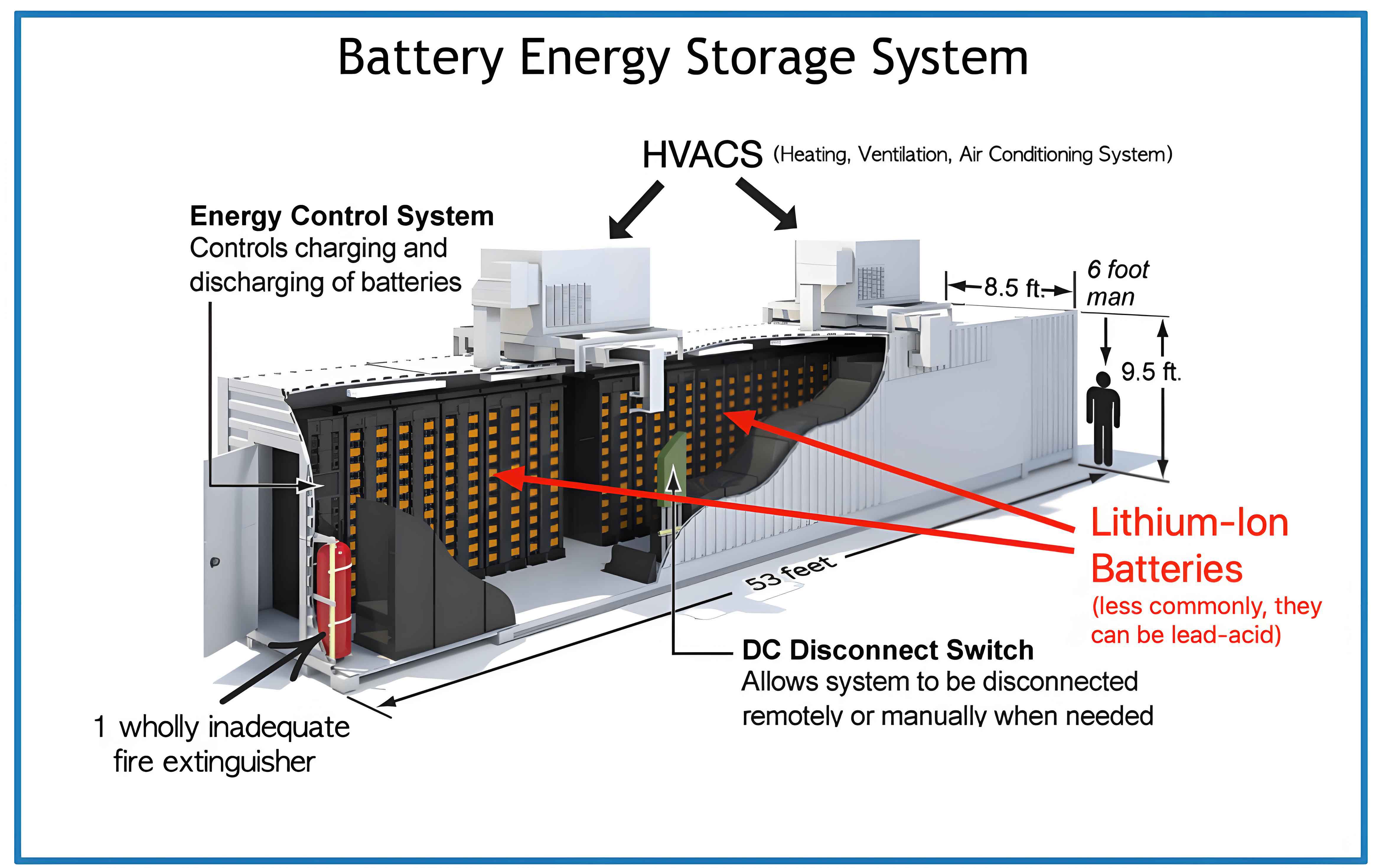
To validate the proposed system, I built a 500 kW prototype. The key parameters of the system are summarized in the table below. The battery bank is a 250 kWh lithium iron phosphate (LFP) energy storage system, which is directly connected to the DC link of the inverter without any intermediate DC/DC converter.
| Parameter | Symbol | Value | Unit |
|---|---|---|---|
| Rated Power | \(P_{rated}\) | 500 | kW |
| Rated AC Line Voltage | \(U_{LL}\) | 315 | V |
| DC Link Voltage (Battery) | \(U_{dc}\) | 800 | V |
| Filter Inductance | \(L_f\) | 0.2 | mH |
| Filter Capacitance | \(C_f\) | 800 | μF |
| Virtual Inertia | \(J\) | 0.1 | kg·m² |
| Droop Coefficient (P/f) | \(D_p\) | 6×10⁴ | W·s/rad |
| Droop Coefficient (Q/V) | \(D_q\) | 2×10⁴ | Var/V |
| Virtual Impedance | \(L_v\) | 0.35 | mH |
| Voltage Loop Integral Gain | \(K_{iu}\) | 200 | — |
| Current Loop Proportional Gain | \(K_{pi}\) | 0.32 | — |
| Current Loop Integral Gain | \(K_{ii}\) | 50 | — |
| Battery Capacity | \(E_{bat}\) | 250 | kWh |
The experimental verification covers the three main operating modes: dual online operation with load steps, mode transition from dual online to battery standalone, active frequency support, and battery charging.
First, I tested the dual online mode. In this mode, the grid and the inverter jointly supply the load. I applied a sudden load increase (from 50% to 100% of rated power) and a sudden load decrease. The results showed that the output voltage remained sinusoidal and stable, with minimal transient overshoot. The inverter’s grid-forming control successfully shared the load power with the grid, demonstrating excellent dynamic performance. The voltage waveform remained within 1% of its nominal value during the transient, confirming the robustness of the autonomous grid-forming control.
Next, I evaluated the mode transition from dual online to battery standalone operation. This is the most critical test for any UPS system. I simulated a grid fault by opening the grid switch. The system needed to switch seamlessly from the dual online mode to the battery standalone mode within milliseconds. The experimental waveforms showed that the transition occurred at zero seconds (0 s) with no detectable interruption. The load voltage experienced a dip of less than 1%, and the load power was entirely taken over by the energy storage system within one fundamental cycle. This seamless transition is a direct result of the autonomous grid-forming control, which always maintains the voltage magnitude and phase angle and can instantly operate as an island without any synchronization delay.
The active frequency support function was validated by introducing a small frequency deviation in the grid when the critical load was supplied solely by the grid. The inverter immediately responded by injecting active power, as illustrated by the measured active current. The response time was less than 100 ms, which is well within the requirements for primary frequency regulation. This capability turns the UPS energy storage system into a valuable grid asset that can help stabilize the grid frequency during normal operation, thereby generating additional revenue or reducing the overall cost of ownership.
Finally, I tested the battery charging control strategies. For constant-voltage (CV) charging with current limiting, the system initially charged the battery at the maximum current limit. As the battery voltage approached the setpoint, the charging current gradually decreased, and the voltage settled to the target value. For constant-current (CC) charging, I performed a step change in the charging current reference from 200 A to 100 A and then back to 200 A. The system accurately tracked the current reference with minimal overshoot, demonstrating excellent regulation performance. The table below summarizes the key experimental results for each test.
| Test Scenario | Key Observation | Performance Indicator |
|---|---|---|
| Dual Online – Load Step (50% to 100%) | Output voltage stable, sinusoidal | Voltage deviation < 1% |
| Dual Online – Load Step (100% to 50%) | Output voltage stable, no overshoot | Settling time < 1 cycle |
| Mode Transition (Dual Online to Battery Standalone) | Seamless, 0 s interruption | Voltage dip < 1% |
| Active Frequency Support | Active power injection within 100 ms | Response time < 100 ms |
| CV Charging with Current Limiting | Current reduces as voltage approaches target | Steady-state error < 0.5% |
| CC Charging (200 A → 100 A → 200 A) | Accurate current tracking | Overshoot < 2% |
In summary, I have successfully proposed and validated a single-stage grid-forming UPS system based on battery energy storage. The main conclusions are as follows: (1) Compared to conventional double-conversion UPS, the proposed architecture requires only a single power conversion stage, which significantly improves the system efficiency. (2) The autonomous grid-forming control strategy enables seamless transition from grid-connected to islanded mode, ensuring an uninterrupted power supply to critical loads. (3) The active voltage and frequency support functions allow the energy storage battery to participate in grid ancillary services, enhancing the overall utilization of the battery system and reducing the total cost of ownership. (4) The experimental results from a 500 kW prototype confirm the feasibility and effectiveness of the proposed system architecture, control strategies, and battery charging management. This work offers a promising solution for modern data centers and industrial applications that demand both high reliability and economic efficiency.