
I approach this topic from the viewpoint of an applied materials researcher working on high-energy lithium ion battery cathodes. The central motivation is simple: increasing the energy density of a lithium ion battery requires a cathode that can deliver high reversible capacity, operate at high voltage, and survive many cycles without catastrophic structural failure. High-nickel layered oxides, especially those with the general formula LiNixCoyMn1−x−yO2 with x ≥ 0.8, satisfy the capacity and cost requirements better than many older cathode chemistries. However, the conventional polycrystalline morphology of these oxides creates a serious reliability problem. In this review, I examine why single-crystal high-nickel cathodes have become one of the most promising solutions for next-generation lithium ion battery systems, and I summarize synthesis routes, failure modes, modification strategies, quantitative design rules, and scale-up considerations. I also use tables and equations to organize the discussion, because the field spans crystal growth, defect chemistry, electrochemistry, and mechanical reliability.
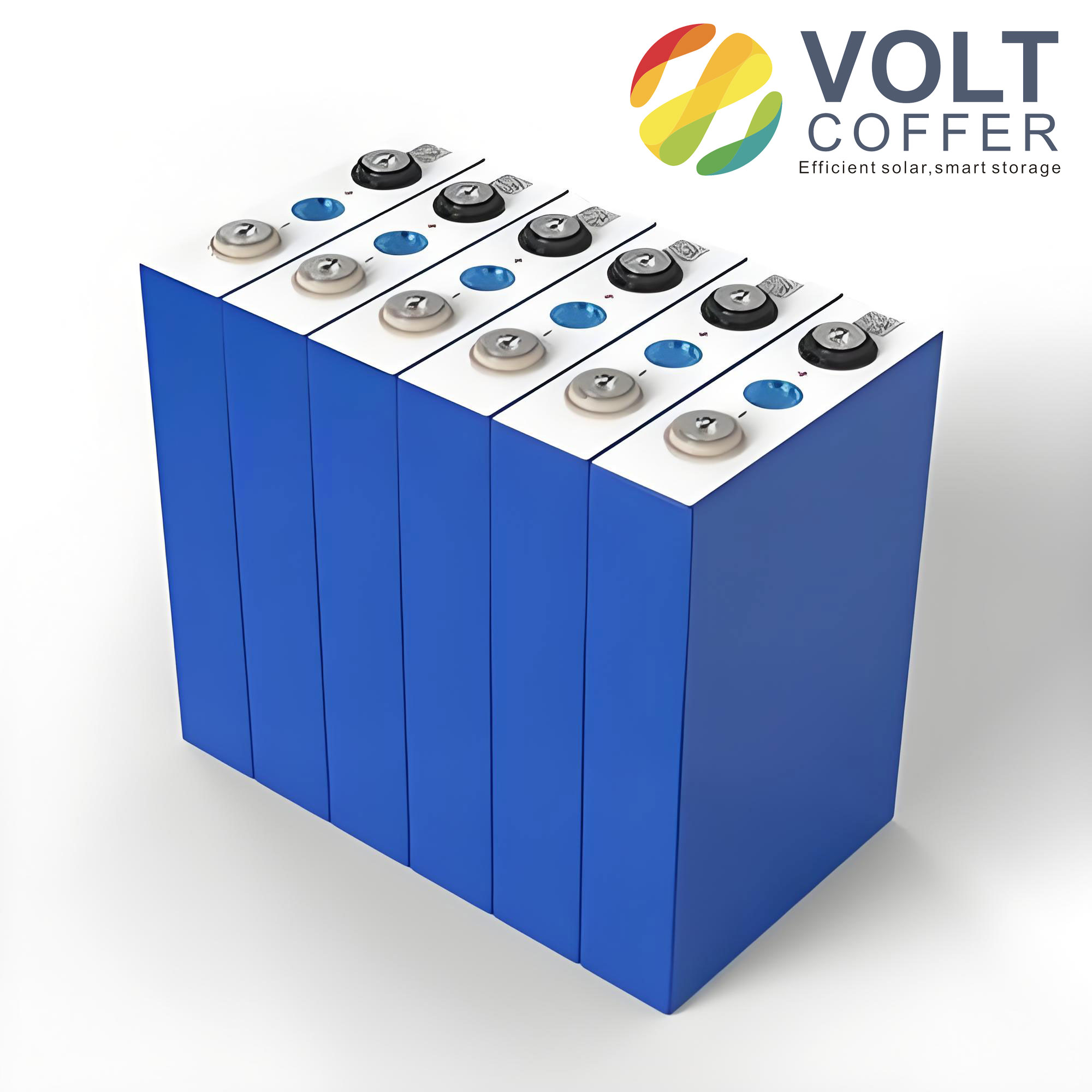
For a lithium ion battery, the cathode is often the limiting component for energy density, cost, and thermal stability. The theoretical energy density of a cell can be expressed in simplified form as
$$E_{\mathrm{cell}} = \frac{\int V(q)\,dq}{m_{\mathrm{cell}}},$$
where \(V(q)\) is the voltage as a function of charge \(q\), and \(m_{\mathrm{cell}}\) is the cell mass. Because cathode active materials contribute a large fraction of cell mass, any improvement in reversible capacity per gram or in average voltage translates into a direct gain in lithium ion battery energy density. Single-crystal high-nickel cathodes are attractive because they preserve the high capacity of nickel-rich layered oxides while reducing the mechanical and interfacial degradation that plague polycrystalline secondary particles.
In my analysis, the most important distinction is not simply “single crystal versus polycrystalline.” It is the coupling between morphology, defect concentration, surface chemistry, and mechanical strain. A single-crystal high-nickel cathode for a lithium ion battery can suppress intergranular cracking because it has no internal grain boundaries. Nevertheless, it can still suffer from Li/Ni disorder, slow lithium diffusion, intragranular fracture, surface reconstruction, residual lithium, and moisture sensitivity. Therefore, I treat single-crystal high-nickel cathodes as a materials design problem rather than a single synthetic target.
1. Why Single-Crystal Architecture Matters for Lithium Ion Battery Cathodes
Conventional high-nickel cathodes are usually polycrystalline secondary particles composed of many randomly oriented primary grains. During charge and discharge, each grain expands and contracts anisotropically. The resulting intergranular strain accumulates at grain boundaries, leading to microcracking. These cracks expose new surfaces to the electrolyte, accelerate side reactions, dissolve transition metals, generate gas, and increase impedance. For a lithium ion battery, this degradation pathway shortens cycle life and worsens safety.
Single-crystal high-nickel cathodes avoid most intergranular boundaries because each particle is a single crystalline domain. This architecture offers several advantages. First, the absence of grain boundaries reduces the number of weak paths for crack propagation. Second, the lower surface area decreases electrolyte contact and side reactions. Third, the mechanical strength of a single crystal can better withstand the volume changes associated with repeated lithium insertion and extraction. Fourth, the surface can be more uniformly coated or doped because the exposed facets are crystallographically coherent.
The capacity retention of a lithium ion battery cathode is commonly expressed as
$$R_{\mathrm{ret}} = \frac{Q_N}{Q_1}\times 100\%,$$
where \(Q_N\) is the discharge capacity after \(N\) cycles and \(Q_1\) is the initial discharge capacity. The Coulombic efficiency is
$$\eta_C = \frac{Q_{\mathrm{dis}}}{Q_{\mathrm{chg}}}\times 100\%.$$
Single-crystal high-nickel cathodes often show improved \(R_{\mathrm{ret}}\) and \(\eta_C\) because they reduce continuous surface reconstruction and electrolyte consumption. However, the improvement is not automatic. If the single crystal is too large, lithium diffusion limitations dominate. If the synthesis temperature is too high, Li/Ni disorder increases. If the surface is not stabilized, residual lithium compounds and moisture attack degrade the material. Hence, I consider single-crystal design as a balance among grain size, defect chemistry, facet exposure, and surface protection.
| Feature | Polycrystalline High-Nickel Cathode | Single-Crystal High-Nickel Cathode |
|---|---|---|
| Particle architecture | Micron-sized secondary sphere made of nanoscale primary grains | Micron or submicron single crystalline particle |
| Grain boundaries | Many; random orientation | Essentially absent within each particle |
| Intergranular cracking | Severe under cycling | Suppressed or eliminated |
| Surface area | High | Lower |
| Electrolyte side reactions | Fast due to fresh surfaces | Reduced, but still dependent on surface chemistry |
| Lithium diffusion path | Short within primary grains, but tortuous across boundaries | Longer within each crystal, requiring careful size control |
| Mechanical integrity | Low due to intergranular weakness | Higher, though intragranular cracks can still occur |
| Thermal stability | Generally poorer | Often improved |
| Scale-up difficulty | Mature industrial route | More demanding sintering and salt removal steps |
I emphasize that the advantage of a single-crystal high-nickel cathode in a lithium ion battery is most pronounced under aggressive conditions: high voltage, high temperature, high loading, and long cycle life. Under mild conditions, the performance gap between polycrystalline and single-crystal materials may be smaller. Therefore, the value of single-crystal architecture depends on the target application.
2. Synthesis Methods for Single-Crystal High-Nickel Cathodes
I now compare the main synthesis methods. Each route influences precursor morphology, cation mixing, grain size, facet exposure, and surface impurities. The optimal method for a lithium ion battery depends on whether the goal is laboratory-scale mechanistic study, kilogram-scale production, or full-cell commercialization.
2.1 Hydrothermal Synthesis
Hydrothermal synthesis uses a sealed reactor with water or an organic solvent at elevated temperature and pressure, typically between 100 and 300 °C. In single-crystal high-nickel cathode research, hydrothermal methods are often used to prepare hydroxide or carbonate precursors with controlled morphology, or occasionally to synthesize lithiated products directly. The high-pressure environment can promote dissolution and recrystallization, yielding rod-like, hexagonal, or monodisperse particles. A lithium ion battery cathode made from such precursors can exhibit ordered layered structure and low Li/Ni disorder if the subsequent calcination is carefully controlled.
I note that hydrothermal synthesis provides good control over particle shape and size distribution. However, the required pressure vessels, relatively high cost, and batch nature limit throughput. For a lithium ion battery intended for mass production, hydrothermal routes are less attractive unless they are integrated with a scalable continuous process.
2.2 Sol–Gel Synthesis
Sol–gel synthesis mixes transition metal salts, lithium sources, and chelating agents such as citric acid in solution. Heating and solvent evaporation produce a viscous gel, which is then calcined to remove organics and form oxide particles. This method can achieve atomic-level mixing and relatively uniform composition. In some cases, porous or foam-like precursors are formed, and subsequent multistep calcination produces single-crystal nickel-rich particles. A lithium ion battery cathode derived from sol–gel processing can show good rate capability if the particle size remains submicron.
From my perspective, the main drawbacks of sol–gel synthesis are the large amount of chelating agent required, the release of combustion gases, and the difficulty of scaling the process economically. It is useful for compositional screening and for introducing dopants uniformly, but it is not yet the most practical route for large-volume lithium ion battery manufacturing.
2.3 Spray Pyrolysis
Spray pyrolysis is a continuous aerosol process. A precursor solution containing transition metal salts and lithium is atomized into fine droplets. The droplets pass through a high-temperature reactor where solvent evaporation, solute precipitation, decomposition, and solid-state reaction occur in seconds. The product is a fine powder that can be further sintered or annealed. Spray pyrolysis is attractive because it is continuous and can produce well-dispersed particles. However, the as-formed particles may be small and highly reactive, leading to severe interfacial side reactions in a lithium ion battery unless a grain growth or annealing step is added.
I have observed that spray pyrolysis is often combined with a post-annealing step to increase particle size from the sub-300 nm range to the submicron range. This improves packing density and reduces surface area. Still, the process involves complex equipment and high energy consumption, which affects cost.
2.4 Co-Precipitation
Co-precipitation is the dominant industrial method for preparing nickel-rich hydroxide precursors. A mixed transition metal sulfate solution is pumped into a reactor together with a chelating agent and a precipitating agent. By controlling pH, temperature, stirring speed, and inert atmosphere, metal ions co-precipitate as dense hydroxide particles. For single-crystal cathodes, the co-precipitation step is followed by lithiation and high-temperature calcination. The particle size and size distribution of the precursor strongly influence the final single-crystal size.
I consider co-precipitation to be the most scalable route for a lithium ion battery because it is already used in commercial cathode production. The main challenge is controlling supersaturation and nucleation so that the precursor particles are uniform and not agglomerated. If the pH or feed rate fluctuates, the final single-crystal high-nickel cathode may contain large grains, fine grains, or undesirable secondary aggregates.
2.5 Solid-State Reaction
Solid-state reaction is simple and industrially familiar. Lithium sources, nickel hydroxide or oxide, cobalt oxide, and manganese oxide are mixed and calcined. For single-crystal growth, the solid-state route typically requires high temperature and sufficient time to promote grain growth. Mechanical densification methods can increase solid–solid contact and reduce the required sintering severity. For example, pellet-assisted mechanical densification can enhance interparticle contact, promote capillary and vacancy-assisted diffusion, and produce single-crystal particles with fewer intergranular defects.
In my view, solid-state synthesis is attractive because it avoids solvents and complex precursor chemistry. However, it can suffer from inhomogeneous mixing, lithium loss, and cation disorder. These issues are especially important for a lithium ion battery cathode because even small amounts of inactive rock-salt phase can increase impedance.
2.6 Molten-Salt Synthesis
Molten-salt synthesis uses low-melting salts such as NaCl, KCl, CsCl, Li2CO3, LiNO3, or Li2SO4 as a liquid medium. The salt provides a liquid phase that accelerates ion diffusion and crystal growth at a lower temperature than conventional solid-state sintering. Mixed salts, such as LiCl–NaCl, LiOH–LiNO3, LiOH–Li2CO3, or LiOH–Li2SO4, can further lower the melting point. This approach can produce well-faceted, smooth single crystals with controlled size. A lithium ion battery cathode made by molten-salt synthesis often shows improved lithium diffusion kinetics and better structural stability.
However, molten-salt synthesis has practical disadvantages. A large amount of salt must be removed by washing, and the washing step can damage the surface or induce lithium extraction. Additional annealing is often needed to restore the surface structure and prevent moisture-driven degradation. Therefore, I regard molten-salt synthesis as a powerful laboratory tool and a promising route for specialty applications, but its cost and waste handling must be improved for large-scale lithium ion battery production.
| Synthesis Method | Typical Temperature | Main Advantage | Main Limitation | Scalability | Typical Single-Crystal Size |
|---|---|---|---|---|---|
| Hydrothermal | 100–300 °C | Morphology and facet control | Pressure vessels, batch process, high cost | Low to medium | Submicron to micron |
| Sol–gel | 400–900 °C after gelation | Atomic-level mixing, uniform doping | Chelating agents, gas emission, cost | Low | Nanoscale to submicron |
| Spray pyrolysis | 600–900 °C | Continuous, fast, good dispersion | Small particles, post-annealing needed | Medium | Sub-300 nm to submicron |
| Co-precipitation | 700–850 °C after precipitation | Industrial maturity, uniform precursors | Sensitive to pH, stirring, atmosphere | High | Submicron to few microns |
| Solid-state | 800–950 °C | Simple, solvent-free | Inhomogeneity, Li loss, cation mixing | High | Micron scale |
| Molten-salt | 700–900 °C | Low-temperature growth, faceted crystals | Salt removal, washing damage, waste | Medium | Submicron to micron |
3. Intrinsic Challenges in Single-Crystal High-Nickel Cathodes
I next discuss the main challenges that limit single-crystal high-nickel cathodes in a lithium ion battery. These challenges are interconnected. For example, Li/Ni disorder reduces lithium diffusion, which increases strain heterogeneity, which promotes intragranular cracking, which exposes fresh surfaces and accelerates surface reconstruction.
3.1 Lithium–Nickel Disorder
In layered LiNixCoyMn1−x−yO2, lithium occupies the 3a site and transition metals occupy the 3b site in the \(R\bar{3}m\) structure. Because Ni2+ has an ionic radius similar to Li+, it can migrate from the transition metal layer to the lithium layer. This is called Li/Ni disorder or cation mixing. A high degree of disorder converts the layered structure into a spinel-like or rock-salt-like arrangement, which blocks lithium transport. For a lithium ion battery, this reduces first-cycle Coulombic efficiency and rate capability.
The equilibrium degree of disorder can be approximated by
$$K_{\mathrm{disorder}} = \exp\left(-\frac{\Delta G_{\mathrm{anti}}}{RT}\right),$$
where \(\Delta G_{\mathrm{anti}}\) is the free energy for antisite exchange, \(R\) is the gas constant, and \(T\) is temperature. Higher synthesis temperature increases the entropy term and can increase disorder, while oxygen loss and lithium volatilization further destabilize the layered structure. Single-crystal high-nickel cathodes often require high calcination temperature, so they are especially vulnerable to Li/Ni disorder. I therefore consider atmosphere control, lithium excess, and cooling rate to be critical variables.
3.2 Slow Lithium Diffusion Kinetics
A single-crystal particle is typically larger than the primary grains in a polycrystalline secondary particle. The characteristic diffusion time is
$$t_d \approx \frac{L^2}{D},$$
where \(L\) is the diffusion length and \(D\) is the lithium diffusion coefficient. If \(L\) increases from tens of nanometers to hundreds of nanometers or microns, \(t_d\) increases quadratically. This can limit rate performance in a lithium ion battery, especially at high current density. The diffusion coefficient is also temperature-dependent:
$$D = D_0 \exp\left(-\frac{E_a}{k_B T}\right),$$
where \(D_0\) is the pre-exponential factor, \(E_a\) is the activation energy, and \(k_B\) is the Boltzmann constant. To improve kinetics, I recommend keeping the single-crystal size in the submicron range when possible, controlling facet exposure to favor fast lithium transport, and introducing dopants that expand the lithium layer or reduce the activation energy.
3.3 Intragranular Cracking
Even without grain boundaries, a single-crystal high-nickel cathode can develop intragranular cracks under aggressive cycling. The driving force is the anisotropic volume change during lithium extraction and insertion. The linear strain can be estimated as
$$\varepsilon = \frac{\Delta L}{L_0},$$
and the volumetric strain as
$$\varepsilon_V \approx 3\varepsilon.$$
The strain energy density is approximately
$$u = \frac{1}{2}E\varepsilon^2,$$
where \(E\) is the Young’s modulus. When the local strain energy exceeds the fracture energy, cracks nucleate. In high-nickel layered oxides, the H2–H3 phase transition at high voltage causes a large \(c\)-axis contraction, which is particularly damaging. The strain associated with this transition can be written as
$$\varepsilon_c = \frac{c_{\mathrm{H3}} – c_{\mathrm{H2}}}{c_{\mathrm{H2}}}.$$
For a lithium ion battery operating to high cutoff voltage, repeated H2–H3 transitions can accumulate damage. Oxygen vacancy diffusion and planar gliding on (003) planes also contribute to intragranular cracking. Once cracks form, they expose new surfaces, increase impedance, and accelerate capacity fade.
3.4 Surface Instability and Residual Lithium
Single-crystal high-nickel cathodes are usually synthesized with excess lithium to compensate for lithium loss at high temperature. This leaves residual lithium compounds such as Li2CO3 and LiOH on the surface. These species are insulating, hygroscopic, and alkaline. They can react with polyvinylidene fluoride binder, cause slurry gelation, and degrade electrode processing. In a lithium ion battery, residual lithium also promotes electrolyte decomposition and gas generation.
Surface instability is further amplified by the high Ni4+ content at high state of charge. Ni4+ is strongly oxidizing and can catalyze electrolyte oxidation. The layered surface can reconstruct into a spinel-like or rock-salt phase, releasing oxygen and increasing interfacial resistance. Moisture exposure can also induce Li+/H+ exchange, forming a lithium-deficient surface. Therefore, I consider surface engineering to be as important as bulk crystal growth.
| Challenge | Root Cause | Consequence for Lithium Ion Battery | Mitigation Strategy |
|---|---|---|---|
| Li/Ni disorder | Similar ionic radii, high-temperature synthesis, oxygen loss | Lower capacity, lower first-cycle efficiency, slower lithium transport | Doping, optimized calcination, oxygen-rich atmosphere, controlled cooling |
| Slow diffusion | Large single-crystal size | Poor rate capability, lithium concentration gradients | Submicron size, facet control, conductive coatings, doping |
| Intragranular cracking | Anisotropic strain, H2–H3 transition, oxygen vacancies | Impedance rise, capacity fade, more surface exposure | Gradient doping, strain buffering, surface coatings, voltage control |
| Surface reconstruction | Ni4+ reactivity, oxygen release | Interfacial resistance, gas evolution, thermal instability | Surface coating, dopant segregation, electrolyte additives |
| Residual lithium | Excess lithium precursors | Slurry gelation, high pH, moisture sensitivity | Washing, annealing, molecular surface treatment |
4. Modification Strategies for High-Performance Single-Crystal High-Nickel Cathodes
I now turn to modification strategies. The goal is to preserve the advantages of single-crystal architecture while addressing Li/Ni disorder, slow diffusion, cracking, and surface instability. In a lithium ion battery, these strategies must also be compatible with electrode processing, electrolyte chemistry, and cell design.
4.1 Elemental Doping
Elemental doping introduces foreign cations or anions into the crystal lattice. Dopants can stabilize the layered structure, expand lithium diffusion pathways, suppress phase transitions, and reduce oxygen release. Common dopants include Na+, Mg2+, Al3+, B3+, Y3+, Zr4+, Ce4+, Ti4+, Nb5+, Te6+, and W6+. The effect depends on valence, ionic radius, site occupancy, and concentration.
For example, low-valence dopants such as Y3+ can form strong metal–oxygen bonds and increase the covalent character of the transition metal–oxygen framework. This suppresses H2–H3 phase transition and oxygen release. High-valence dopants such as Nb5+ can act as structural pillars, enlarge interlayer spacing, and stabilize oxygen. Co-doping with Al3+ and Ti4+ can combine cation-disorder suppression with lattice oxygen stabilization. In my view, gradient doping is often superior to uniform doping because it places the dopant where it is most needed: near the surface for interfacial stability and in the bulk for structural support.
| Dopant | Typical Valence | Preferred Site | Primary Function | Potential Tradeoff |
|---|---|---|---|---|
| Na+ | +1 | Li site | Pillaring effect, widened lithium channels | Too much Na lowers capacity |
| Mg2+ | +2 | Li or transition metal site | Suppresses oxygen release, stabilizes structure | Can reduce lithium content |
| Al3+ | +3 | Transition metal site | Suppresses Li/Ni disorder, strengthens metal–oxygen bonds | Excess Al lowers capacity |
| B3+ | +3 | Interstitial or surface | Grain boundary modification, surface stabilization | Limited bulk solubility |
| Y3+ | +3 | Transition metal site | Enhances metal–oxygen covalency, suppresses H2–H3 | Large radius may distort lattice |
| Ti4+ | +4 | Transition metal site | Improves lithium diffusion, stabilizes oxygen | Can reduce Ni content |
| Nb5+ | +5 | Transition metal site | Pillaring effect, suppresses oxygen release | High valence may increase impedance if excessive |
| Ta5+ | +5 | Transition metal site or coating | Suppresses side reactions and Li/Ni disorder | Cost and uniform distribution |
| W6+ | +6 | Transition metal site | Surface stabilization, oxygen retention | May form secondary phases |
4.2 Surface Coating Modification
Surface coating is a direct method to isolate the high-nickel surface from the electrolyte. A suitable coating must be chemically stable, mechanically robust, and permeable to lithium ions. It should also be thin enough to avoid increasing impedance. Coatings can be classified into oxides, fluorides, phosphates, conductive polymers, lithium-ion conductors, and organic molecular layers.
Oxide coatings such as Al2O3, TiO2, and Ta2O5 can suppress interfacial side reactions and cation mixing. Higher-valence oxide coatings often show stronger improvement because they can also induce surface doping. Phosphate-based coatings such as Li3PO4 and LiPO2F2-derived layers can improve lithium transport and stabilize the cathode–electrolyte interface. Fluoride coatings such as LiF are attractive because they are chemically resistant and can form a robust interface. Conductive networks such as Li1.3Al0.1Sc0.2Ti1.7(PO4)3 can provide fast lithium pathways while bonding to the surface.
Organic molecular layers are another promising direction. Molecules with hydrophobic tails and functional head groups can react with residual lithium, neutralize surface alkalinity, and prevent moisture attack. In a lithium ion battery, such layers can improve slurry processing, storage stability, and cycling performance. I find this approach especially interesting because it addresses multiple problems at once: residual lithium, moisture sensitivity, and interfacial instability.
| Coating Type | Examples | Main Function | Effect on Lithium Ion Battery Performance |
|---|---|---|---|
| Oxide | Al2O3, TiO2, Ta2O5, ZrO2 | Physical barrier, surface doping in some cases | Reduced side reactions, improved cycling |
| Fluoride | LiF, AlF3 | Chemical protection, stable interface | Improved high-voltage stability, lower gas generation |
| Phosphate | Li3PO4, LiPO2F2-derived | Fast lithium transport, interface stabilization | Higher rate capability, lower impedance growth |
| Lithium-ion conductor | Li1.3Al0.1Sc0.2Ti1.7(PO4)3 | 3D conductive network, oxygen vacancy stabilization | Long cycle life, improved high-temperature performance |
| Organic molecular layer | Hydrophobic silanes, boronic acid derivatives | Removes residual lithium, repels moisture | Better storage stability, improved processing |
| Composite coating | LiF–Li3PO4, oxide–polymer | Combined ionic conduction and chemical protection | Synergistic improvement in rate and cycling |
4.3 Crystal Facet Engineering
Crystal facet engineering controls which crystallographic planes are exposed at the surface of a single-crystal high-nickel cathode. Different facets have different surface energies, atomic arrangements, and reactivity with the electrolyte. For layered oxides, common facets include (001), (012), (104), and (003). The (001) facet is the basal plane, while (104) and (012) are more accessible for lithium diffusion. Increasing the exposure of fast lithium transport facets can improve rate capability in a lithium ion battery.
The facet exposure can be tuned by oxygen and lithium chemical potential during synthesis. Lower oxygen chemical potential, achieved by reducing oxygen partial pressure, lowering calcination temperature, or shortening calcination time, tends to increase (104) exposure. Lower lithium chemical potential tends to promote (001) exposure. Molten-salt media can also selectively inhibit or promote certain facets. For example, bromide-containing salts can increase (104) exposure, which enhances lithium diffusion and reduces oxygen vacancy formation.
The relationship between facet exposure and electrochemical performance can be expressed qualitatively as
$$D_{\mathrm{eff}} = \sum_i f_i D_i,$$
where \(f_i\) is the area fraction of facet \(i\) and \(D_i\) is the lithium diffusion coefficient on that facet. A higher fraction of fast-diffusion facets increases the effective diffusion coefficient. However, facets with high reactivity may also catalyze electrolyte decomposition. Therefore, facet engineering must be combined with surface passivation.
| Facet | Structural Character | Lithium Transport | Surface Reactivity | Design Implication |
|---|---|---|---|---|
| (001) | Basal plane, close-packed | Relatively slow | Lower | Can improve stability but may limit rate |
| (012) | Stepped surface | Moderate | Moderate | Balanced performance |
| (104) | Fast lithium pathway | Fast | Higher | Improves rate but needs coating |
| (003) | Layered stacking plane | Variable | High | Can promote gliding and cracking if unstable |
4.4 Synergistic Bulk and Surface Engineering
I strongly favor synergistic modification because single-crystal high-nickel cathodes fail through coupled bulk and surface mechanisms. A bulk dopant can stabilize the lattice and reduce strain, while a surface coating can protect against electrolyte attack. For example, combining Al bulk doping with LiF surface coating can reduce Li/Ni disorder, suppress intragranular cracking, and improve interfacial stability. In a lithium ion battery, this dual strategy can simultaneously improve reversible capacity, rate capability, and cycle life.
The synergy can be represented as
$$P_{\mathrm{total}} \approx P_{\mathrm{bulk}} + P_{\mathrm{surface}} + P_{\mathrm{coupling}},$$
where \(P_{\mathrm{bulk}}\) is the bulk stabilization effect, \(P_{\mathrm{surface}}\) is the interfacial protection effect, and \(P_{\mathrm{coupling}}\) is the additional benefit from interactions between them. In practice, the coupling term is often the most important because a stable bulk reduces surface reconstruction, and a stable surface reduces bulk degradation.
5. Quantitative Benchmarks and Design Rules
To compare different single-crystal high-nickel cathodes for a lithium ion battery, I use several quantitative metrics: initial discharge capacity, first-cycle Coulombic efficiency, capacity retention, rate capability, voltage fade, impedance growth, and thermal stability. Table 7 summarizes general ranges reported in the literature without attributing them to specific groups.
| Metric | Typical Polycrystalline High-Nickel | Typical Single-Crystal High-Nickel | Improved Single-Crystal with Modifications |
|---|---|---|---|
| Initial discharge capacity at 0.1C | 200–220 mAh/g | 190–225 mAh/g | 200–230 mAh/g |
| First-cycle Coulombic efficiency | 85–90% | 88–93% | 90–95% |
| Capacity retention after 100 cycles at 1C | 70–85% | 85–95% | 90–98% |
| Capacity retention after 500 cycles at 1C | 60–75% | 75–88% | 82–92% |
| Rate capacity at 10C | 120–150 mAh/g | 140–170 mAh/g | 160–180 mAh/g |
| Voltage fade after 200 cycles | High | Moderate | Low |
| Thermal stability | Lower onset temperature | Higher onset temperature | Highest onset temperature |
From these metrics, I derive several design rules. First, the single-crystal size should be large enough to reduce surface area but small enough to keep lithium diffusion paths short. A practical target is often 0.3–2 μm, with submicron sizes preferred for high-rate lithium ion battery applications. Second, the Li/Ni disorder should be minimized, ideally below a few percent, because disorder directly reduces capacity and rate capability. Third, the surface should be free of insulating residual lithium species and protected by a thin, lithium-conducting coating. Fourth, dopants should be chosen to strengthen metal–oxygen bonds and suppress H2–H3 phase transition without blocking lithium diffusion. Fifth, the synthesis atmosphere and cooling rate must be controlled to avoid oxygen loss and surface reconstruction.
The optimal doping level can be estimated by balancing capacity loss and stability gain. If a dopant replaces nickel, the theoretical capacity decreases approximately as
$$Q_{\mathrm{theo}} \approx Q_{\mathrm{Ni}} (1 – x_{\mathrm{dopant}}),$$
where \(Q_{\mathrm{Ni}}\) is the capacity contribution of nickel and \(x_{\mathrm{dopant}}\) is the dopant fraction. At the same time, the cycle life may increase according to an empirical relation such as
$$N_{\mathrm{life}} \approx N_0 \exp(\beta x_{\mathrm{dopant}}),$$
where \(N_0\) is the baseline cycle life and \(\beta\) is a system-dependent constant. The practical optimum is usually a compromise, often in the range of 0.5–3 mol% for many dopants. I emphasize that these are approximate guidelines, not universal laws.
| Design Variable | Recommended Range | Reason | Risk if Outside Range |
|---|---|---|---|
| Single-crystal size | 0.3–2 μm | Balance surface area and diffusion length | Too small: side reactions; too large: slow diffusion |
| Li/Ni disorder | <3–5% | Maintain layered structure and lithium pathways | Higher disorder lowers capacity and rate |
| Dopant content | 0.5–3 mol% | Stabilize lattice without excessive capacity loss | Too low: little effect; too high: lower capacity |
| Coating thickness | 1–10 nm | Protect surface without blocking lithium | Too thick: impedance rise; too thin: incomplete protection |
| Calcination temperature | 700–900 °C | Promote crystal growth while limiting disorder | Too low: incomplete reaction; too high: Li loss and disorder |
| Oxygen partial pressure | Controlled, often oxygen-rich | Suppress oxygen vacancies and surface reconstruction | Too low: oxygen loss; too high: cost and safety |
| Residual lithium | As low as possible | Improve processing and interfacial stability | High residual lithium causes gelation and gas |
6. Characterization and Advanced Diagnostics
I cannot overstate the importance of characterization in developing single-crystal high-nickel cathodes for a lithium ion battery. Because the material is metastable and sensitive to air and beam damage, ex situ measurements alone can be misleading. In situ and operando techniques are needed to link synthesis parameters to electrochemical behavior.
X-ray diffraction provides lattice parameters, cation mixing, and phase transitions. Rietveld refinement can quantify the fraction of rock-salt phase and Li/Ni disorder. Scanning electron microscopy reveals particle morphology and size distribution. Transmission electron microscopy provides atomic-scale information on surface reconstruction and intragranular cracks. X-ray photoelectron spectroscopy identifies surface species such as Li2CO3, LiOH, and Ni3+/Ni4+. Differential electrochemical mass spectrometry detects gas evolution. In situ X-ray diffraction tracks the H2–H3 transition during cycling. Density functional theory can calculate dopant binding energies, oxygen vacancy formation energies, and lithium migration barriers.
| Technique | Information Obtained | Relevance to Single-Crystal High-Nickel Cathodes |
|---|---|---|
| X-ray diffraction | Lattice parameters, phase purity, cation mixing | Quantifies layered structure and impurity phases |
| Rietveld refinement | Site occupancy, Li/Ni disorder | Links synthesis to cation mixing |
| Scanning electron microscopy | Particle size, morphology, agglomeration | Evaluates single-crystal quality |
| Transmission electron microscopy | Atomic structure, surface reconstruction, cracks | Reveals intragranular damage and phase changes |
| X-ray photoelectron spectroscopy | Surface composition and oxidation states | Identifies residual lithium and Ni oxidation |
| Differential electrochemical mass spectrometry | Gas evolution | Assesses safety and electrolyte decomposition |
| In situ X-ray diffraction | Dynamic phase transitions | Tracks H2–H3 transition and lattice strain |
| Electrochemical impedance spectroscopy | Interfacial and charge-transfer resistance | Quantifies impedance growth in lithium ion battery cells |
| Density functional theory | Defect energetics and migration barriers | Explains dopant and coating effects |
I also recommend combining electrochemical testing with post-mortem analysis. For example, after cycling a single-crystal high-nickel cathode in a lithium ion battery, cross-sectional focused ion beam scanning electron microscopy can reveal whether cracks are intergranular or intragranular. If cracks are mostly intragranular, then bulk strain management and dopant engineering should be prioritized. If surface reconstruction dominates, then coating and electrolyte optimization are more important.
7. Scale-Up, Cost, and Safety Considerations
For single-crystal high-nickel cathodes to be adopted in a commercial lithium ion battery, they must be manufactured at scale with acceptable cost and safety. The synthesis routes that require high-pressure reactors, large amounts of chelating agents, or excessive molten salt are less attractive. Co-precipitation followed by optimized calcination remains the most scalable route. Molten-salt synthesis may be used for premium applications, but salt recycling and washing must be improved.
Energy consumption is a major cost factor. High-temperature calcination and long annealing times increase the embodied energy of the cathode. A lithium ion battery with a lower-cost cathode but higher processing energy may not be economically superior. Therefore, I suggest that future work should focus on lowering calcination temperature, shortening calcination time, and using atmosphere control to suppress disorder. Doping and coating can sometimes allow lower sintering temperatures, which improves both cost and material quality.
Safety is another critical consideration. High-nickel cathodes release oxygen at elevated temperature, especially when delithiated. Single-crystal architecture reduces surface area and suppresses some oxygen release, but it does not eliminate the risk. Surface coatings, dopants that strengthen metal–oxygen bonds, and electrolyte additives that form stable interfaces can improve thermal stability. In a lithium ion battery, cell-level testing under abuse conditions is essential. The onset temperature of exothermic decomposition, total heat release, and gas composition should be measured.
| Scale-Up Factor | Challenge | Possible Solution | Expected Impact |
|---|---|---|---|
| Precursor cost | High-purity salts and chelating agents | Co-precipitation with recycled water and reagents | Lower cost, lower waste |
| Calcination energy | High temperature and long time | Doping, molten-salt flux, optimized heating profile | Reduced energy consumption |
| Salt removal | Washing damages surface | Water-free washing, solvent washing, annealing | Better surface stability |
| Residual lithium | Slurry gelation and gas generation | Surface treatment, molecular neutralizing layers | Improved processing and safety |
| Particle size control | Batch-to-batch variation | In-line sensing, automated pH and feed control | Consistent lithium ion battery performance |
| Moisture sensitivity | Storage and handling | Hydrophobic coatings, dry-room manufacturing | Longer shelf life |
| Thermal stability | Oxygen release at high state of charge | Coating, doping, electrolyte additives | Improved safety |
8. Outlook and Future Directions
In my assessment, single-crystal high-nickel cathodes will play a central role in the next generation of high-energy lithium ion battery systems, but their success depends on integrated materials engineering. The most promising directions are as follows.
First, I expect continued progress in low-temperature growth of single crystals. If high-quality single crystals can be grown below 800 °C, Li/Ni disorder and oxygen loss can be reduced, and manufacturing cost can be lowered. Molten-salt fluxes and dopants that lower the activation energy for grain growth are promising.
Second, I anticipate that gradient and multifunctional doping will become standard. A single dopant rarely solves all problems. A combination of a bulk stabilizer, a surface segregant, and a lithium-conducting coating can address multiple degradation modes. The challenge is to control spatial distribution at the nanoscale.
Third, I believe that crystal facet engineering will mature into a quantitative design tool. By controlling the fraction of (104), (012), and (001) facets, researchers can tune lithium diffusion, surface reactivity, and mechanical strain. Machine learning and high-throughput experiments can help identify optimal facet combinations for a given lithium ion battery application.
Fourth, I expect more emphasis on full-cell testing. Many promising single-crystal high-nickel cathodes are tested in coin cells with lithium metal anodes and flooded electrolyte. These conditions are not representative of practical lithium ion battery cells. High-loading electrodes, lean electrolyte, silicon or graphite anodes, and wide temperature ranges must be evaluated. Scale-up requires consistency in particle size, coating thickness, and surface chemistry.
Fifth, I see opportunities in coupling single-crystal cathodes with advanced electrolytes. Electrolyte additives can form stable cathode–electrolyte interphases and suppress gas generation. Solid-state electrolytes may also benefit from single-crystal cathodes because the absence of grain boundaries reduces interfacial reactions and mechanical degradation. In a solid-state lithium ion battery, single-crystal cathodes may enable higher voltage and longer life.
Finally, I emphasize sustainability. The production of high-nickel cathodes involves nickel, cobalt, and lithium, all of which have environmental and supply-chain impacts. Reducing cobalt content, increasing nickel utilization, and recycling spent cathodes are important. Single-crystal cathodes may be easier to recycle because they are chemically homogeneous and have fewer grain boundaries, which can simplify separation and regeneration.
In conclusion, single-crystal high-nickel cathodes offer a compelling pathway to improve the energy density, cycle life, and safety of lithium ion battery systems. They suppress intergranular cracking, reduce surface side reactions, and provide a robust platform for doping, coating, and facet engineering. However, they also introduce new challenges, including Li/Ni disorder, slow lithium diffusion in large crystals, intragranular cracking, residual lithium, and moisture sensitivity. I have summarized synthesis methods, failure mechanisms, modification strategies, quantitative design rules, characterization techniques, and scale-up considerations. The field is moving toward synergistic bulk–surface engineering, precise facet control, low-temperature synthesis, and full-cell validation. With continued progress, I believe single-crystal high-nickel cathodes will become a key enabler of next-generation lithium ion battery technologies for electric vehicles, grid storage, and portable electronics.