
With the rapid development of rail transit technology and the increasing demand for rail vehicle operation by the people, more and more rail vehicles have been put into large-scale use and operation in recent years. With the deployment of numerous rail vehicles, the development and utilization of hybrid rail vehicles have received increasing attention from various manufacturers in order to meet the needs of different operating line environments. As a new type of energy storage power source for rail vehicles, supercapacitors have attracted increasing attention from the rail transit industry due to their high power density, wide temperature characteristics, and excellent environmental adaptability. They have gradually been applied to hybrid rail vehicles, such as the diesel engine/supercapacitor hybrid locomotive developed by the research team of the Swiss Federal Institute of Technology, Bombardier developed feeder/supercapacitor hybrid light rail vehicles, and Japan developed feeder/supercapacitor hybrid 313 series EMUs.
The internal temperature of supercapacitors directly affects multiple important indicators such as the efficiency, safety, and service life of energy storage power supplies. Therefore, temperature rise control is an important factor to consider in the design of energy storage power supplies. In order to study the temperature rise control and optimized heat dissipation design of the energy storage power supply for a certain hybrid electric multiple unit, and analyze the temperature distribution inside the energy storage power supply during stable operation of the vehicle, this paper adopts the computational fluid dynamics (CFD) calculation method to simulate the temperature field of the energy storage power supply. Based on the calculation results, an optimized heat dissipation scheme for the energy storage power supply is proposed, and the optimized scheme is verified, Provide reference for the design of energy storage power sources.
1. Energy storage power supply structure and heat dissipation design
The energy storage power supply box of a certain hybrid electric multiple unit is shown in Figure 1 (the box has been cut open for easy observation). The internal supercapacitor module is divided into two layers: upper and lower. There are 6 air inlet ports on the top of the box, and 6 suction fans on both sides of the box near the bottom as exhaust ports. The working voltage of the energy storage power supply is 630-870 V, the maximum continuous current is 600 A, and the inlet air volume is 1000 m3/h. The heat dissipation process of the energy storage power supply box is as follows:
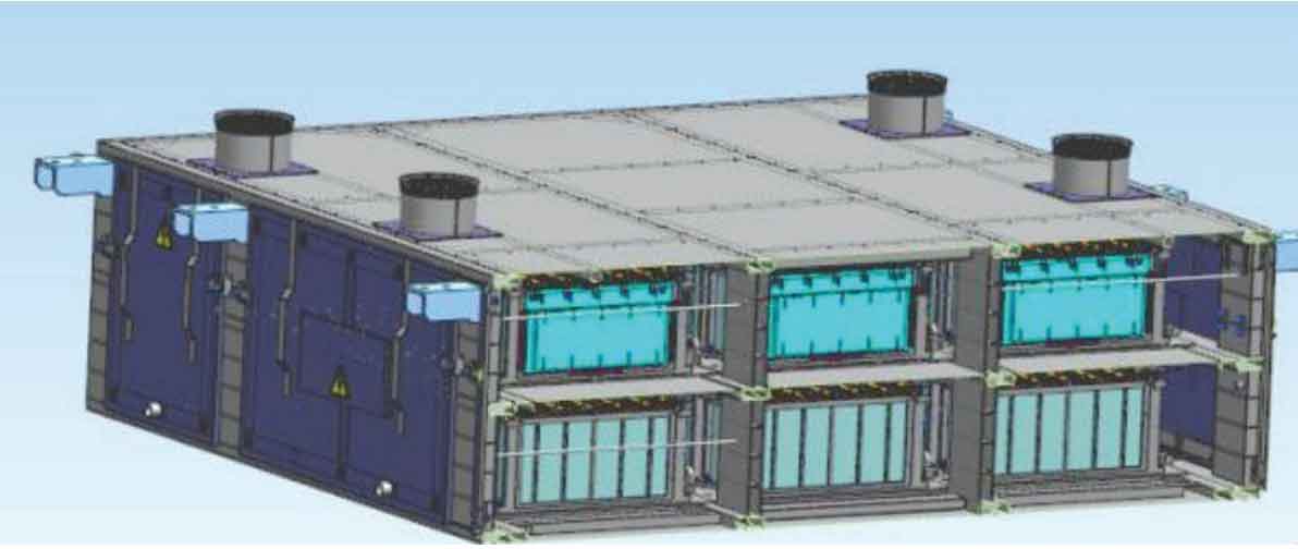
Under the combined action of positive pressure and suction fan in the car, the air inside the passenger compartment is sucked into the energy storage power supply box to achieve heat dissipation of the energy storage power supply.
Based on the operating current of the entire high-speed train line, the average heating power of the entire energy storage power supply can be obtained, thereby calculating the unit volume heat generation of the supercapacitor.
Due to the significant differences in the arrangement of the supercapacitors inside the energy storage power supply of this high-speed train compared to other projects before, it is necessary to use CFD calculation method to simulate the heat dissipation of its energy storage power supply in order to preliminarily grasp the temperature distribution inside the energy storage power supply box during the design phase, verify the rationality of the arrangement of the supercapacitors and the design of the air duct.
2. Numerical calculation model for heat dissipation of energy storage power supply
2.1 Simplification of Energy Storage Power Box Model
The energy storage power box contains many very small components such as bolts and nuts, and the minimum gap between each component is only 3 mm. The internal structure is very complex. In order to achieve numerical calculations, it is necessary to discretize the geometric region, and the quality of the mesh used for discretization will directly affect the convergence and accuracy of numerical calculations. Therefore, in order to generate a high-precision and regular full hexahedral computational mesh, the geometric structure of the energy storage power box has been simplified.
Due to the complexity of the internal structure of supercapacitor cells, it is difficult to grasp the temperature distribution of supercapacitor cells in practical applications. Therefore, supercapacitor cells are approximately simplified as a uniform heating element.
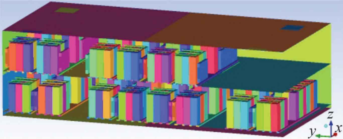
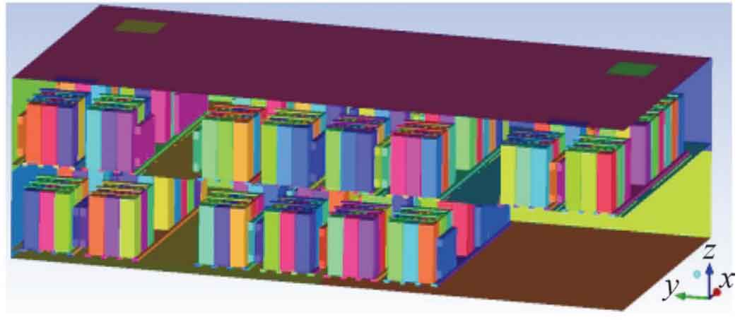
The entire energy storage power box has a 1/2 symmetrical structure in the horizontal view direction. The 1/2 structure of the box is taken for simulation calculation. The simplified geometric model of the energy storage power box is shown in Figure 2.
The exterior of the energy storage power supply box is coated with insulation paint. In order to simplify the calculation, the temperature difference between the inside and outside of the box is ignored, so the convective heat transfer between the air inside the energy storage power supply box and the wall surface of the capacitor box can be ignored.
2.2 Calculation Model
The energy storage power box uses air in the passenger compartment for heat dissipation, which belongs to a typical forced convection heat transfer physical process. Each supercapacitor unit is a heat source, and the air in the passenger compartment flows through the surface of the supercapacitor unit, exchanging heat with the capacitor surface and taking away the heat, thereby achieving the effect of heat dissipation.
In simulation calculations, not only the flow and heat transfer of air should be considered, but also the conduction of thermal energy inside the solid. Therefore, the fluid structure coupling heat transfer calculation method needs to be adopted. Establish the fluid computational domain and solid computational domain in the calculation, and then establish the coupling relationship between the fluid solid contact surface [4]. Using a hexahedral mesh to discretize the computational domains of fluids and solids, utilizing k- ε Turbulence model simulation, using commercial computational fluid dynamics software based on finite volume method for calculation.
According to the airflow and temperature conditions of the heat dissipation scheme, the inlet adopts a velocity inlet boundary condition, which is converted into the corresponding velocity based on the ventilation airflow. The outlet adopts a pressure outlet boundary condition with a pressure of 1 standard atmospheric pressure.
3. Simulation calculation and optimization of heat dissipation for energy storage power supply
3.1 Simulation Calculation and Result Analysis
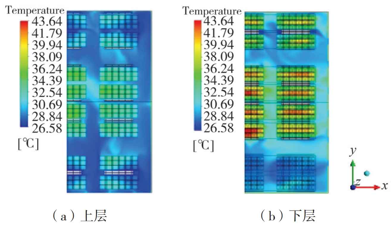
Cooling of the supercapacitor was carried out using an air flow of 27 ℃ and 1000 m ^ 3/h, and a simulation calculation model was established for numerical solution and post-processing. Through post-processing, it can be obtained that the highest internal temperature of the energy storage power supply is 48.23 ℃, located in the lower module; The highest temperature of the air inside the box is 44.848 ℃, located in the negative y-axis direction near the surface of the supercapacitor unit in the lower layer. The temperature distribution cloud map of the upper and lower modules is shown in Figure 3.
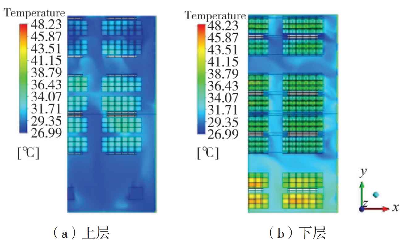
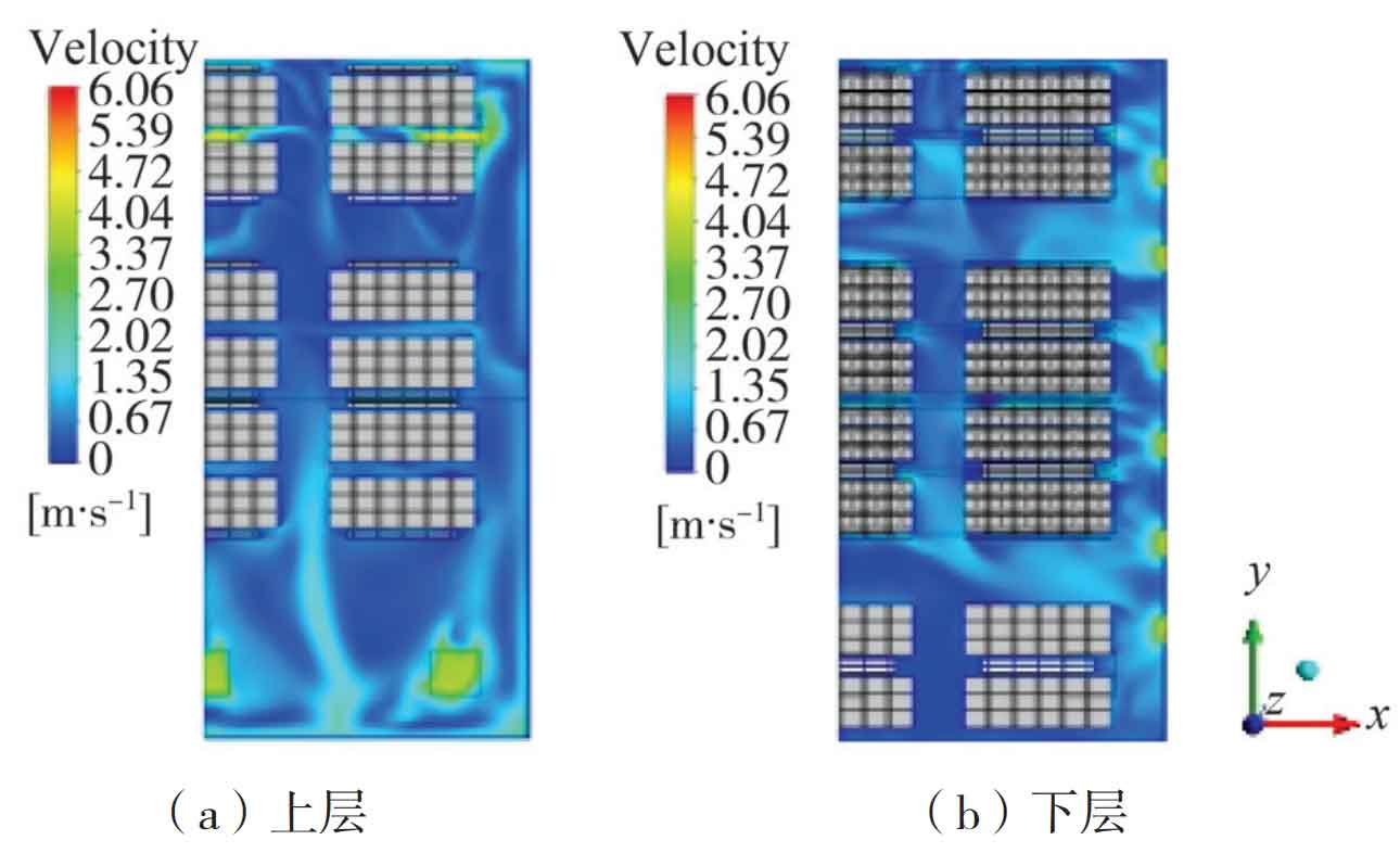
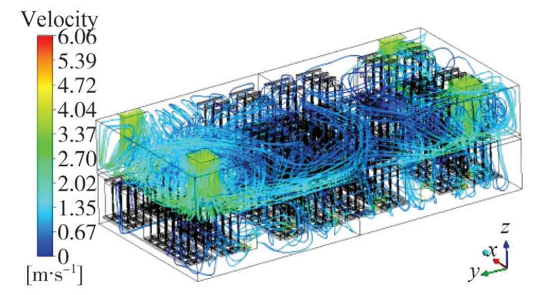
Figure 4 shows the velocity distribution cloud map of the upper and lower modules. Figure 5 shows the flow trajectory of the flow field inside the energy storage power supply box. From the velocity distribution cloud map and flow field flow trace map, it can be seen that in the area with high temperature in the lower module, the air flow velocity is relatively low, resulting in poor heat dissipation effect. Based on this situation, improvements can be made by changing the internal layout of energy storage power sources.
After the above calculation and analysis, it can be concluded that the highest internal temperature of the energy storage power supply is 48.23 ℃, which meets the requirements of safe operation. The designed air volume and inlet air temperature are reasonable. However, the initial design has issues with the highest temperature approaching the alarm temperature and uneven temperature distribution. The service life of supercapacitor cells with relatively high temperatures will be lower than that of other supercapacitor cells, and long-term use will bring certain safety hazards. Therefore, optimization is needed.
3.2 Optimization Plan and Calculation
3.2.1 Optimization ideas and methods
Due to the installation of the energy storage power box on the top of the high-speed train, the original design scheme considered the convenience of installation and maintenance for the arrangement of supercapacitors, with more lower level modules than upper level modules. But from Figures 3 and 4, it can be seen that the upper module has a lower temperature, while the lower module has a higher temperature near the negative y-axis side. The main reason for the high temperature in the area is that there are no supercapacitors arranged in the upper layer corresponding to the high temperature area, and there is no gap for the downward flow of gas supply. To solve this problem, considering that cold air flows from bottom to top, swap the upper and lower layers of modules on the right side of the model (negative y-axis side). The geometric model of the module layout optimization scheme is shown in Figure 6.
3.2.2 Optimization Plan Simulation Calculation
Establish a computational grid for the above optimization plan and conduct simulation calculations. Through post-processing, it can be obtained that the highest internal temperature of the energy storage power supply is 43.64 ℃, located in the lower module; The highest temperature of the air inside the box is 42.673 ℃, located in the middle area of the lower module near the surface of the supercapacitor unit. The temperature distribution cloud map of the upper module is shown in Figure 7.
From the calculation results, it can be seen that the maximum temperature of the supercapacitor and the maximum temperature of the air inside the energy storage power supply box have significantly decreased, and the temperature distribution inside the box is more uniform.
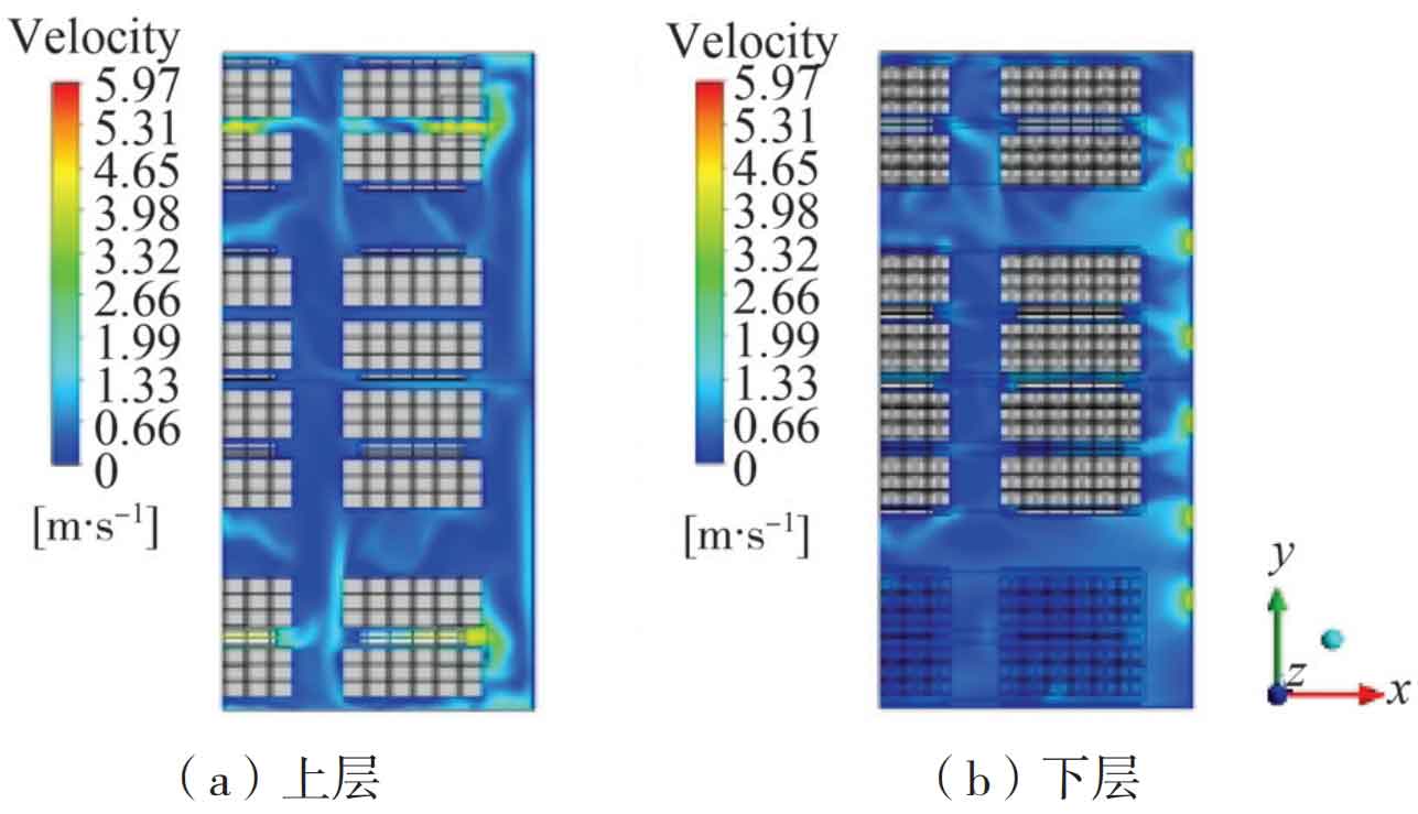
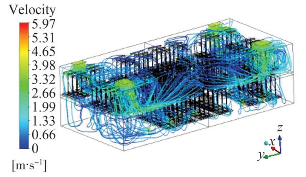
Figure 8 shows the velocity distribution cloud map of the upper and lower modules. Figure 9 shows the flow trajectory of the flow field inside the energy storage power supply box. From the velocity distribution cloud map and flow trace map, it can be seen that after adopting the optimization scheme, the difference in air flow velocity between the upper and lower layers is significantly reduced compared to the original scheme. This also indirectly confirms that the temperature distribution inside the energy storage power supply box is more uniform after optimization.
3.2.3 Analysis of Optimization Plan Calculation Results
By adjusting the arrangement of supercapacitors inside the energy storage power supply without changing the cooling airflow and temperature, the maximum temperature inside the energy storage power supply can be reduced from 48.23 ℃ to 43.64 ℃. At the same time, the maximum temperature of the air inside the energy storage power supply box decreased from 44.848 ℃ to 42.673 ℃. From the above results, it can be seen that through the optimization of the original design scheme, the maximum temperature inside the energy storage power supply has significantly decreased, and the temperature distribution is more uniform, further ensuring the safety of the energy storage power supply.
3.2.4 Optimization Plan Real Vehicle Test
According to the above optimization plan, a nearly 2-hour actual vehicle test was conducted on the power line, and the highest temperature curve inside the energy storage power supply is shown in Figure 10.
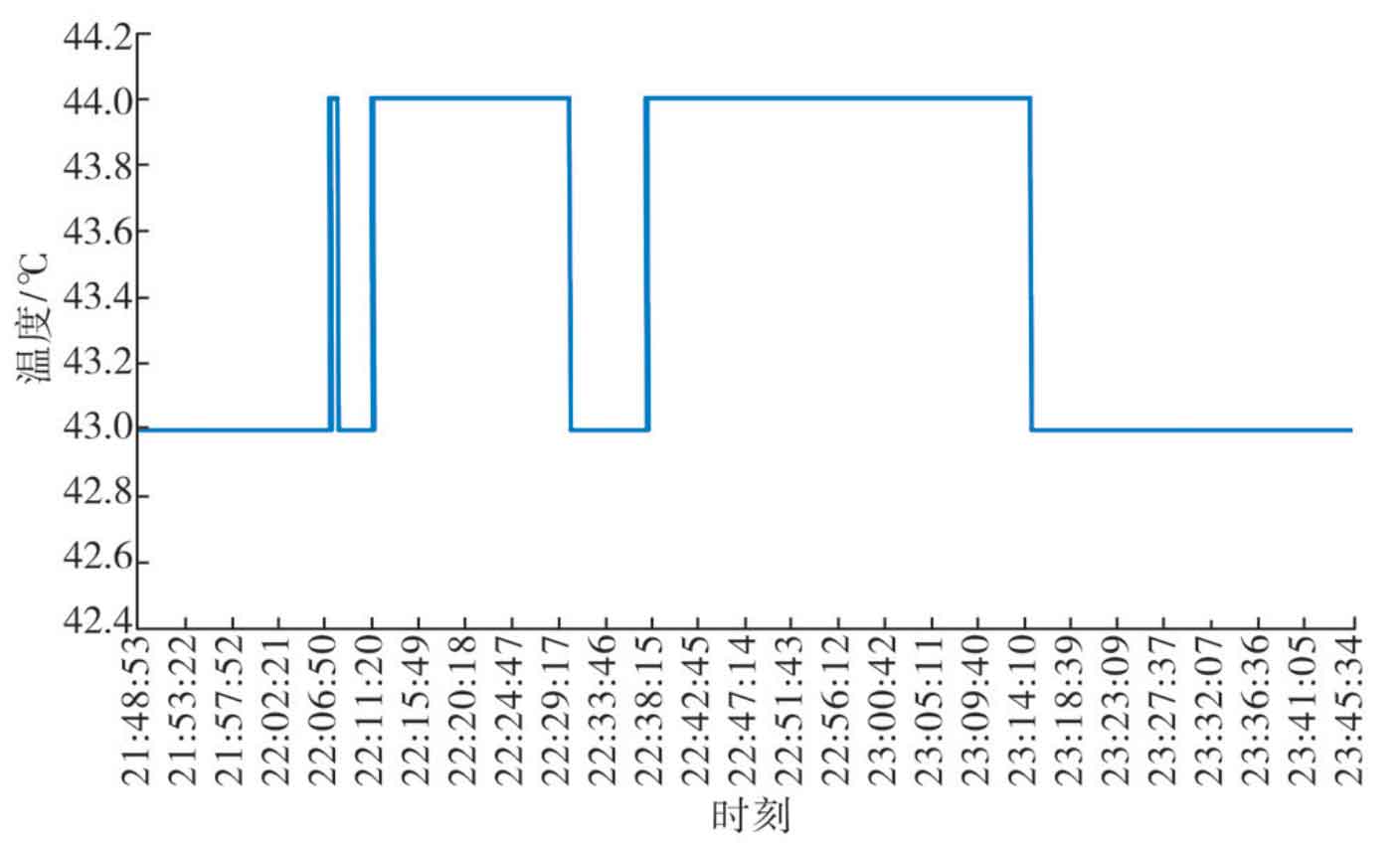
From the actual vehicle test results, it can be seen that the highest temperature of the energy storage power supply during the testing period is 44 ℃, which is in good agreement with the simulation results.
4. Conclusion
Taking a hybrid electric multiple unit energy storage power supply as the research object, the internal temperature field during stable operation was simulated and calculated using CFD calculation method. Based on the calculation results, it was analyzed that the original arrangement of supercapacitors has a significant impact on the internal temperature distribution of energy storage power sources. Based on this analysis, adjustments were made to the arrangement of supercapacitors. Simulation calculations were conducted on the adjusted optimization scheme, and the results showed that by adjusting the arrangement of supercapacitors, the maximum temperature inside the energy storage power supply box can be effectively reduced, while improving the uniformity of temperature distribution inside the box. In addition, the results of the optimization plan’s actual vehicle test are consistent with the simulation results, verifying the rationality of the optimization plan.