
The relentless pursuit of sustainable and clean energy sources has positioned thin film solar panel technology at the forefront of photovoltaic research. Among the various absorber materials, kesterite Cu2ZnSnS4 (CZTS) has emerged as a highly promising candidate for next-generation thin film solar panels due to its optimal optoelectronic properties and earth-abundant, non-toxic constituents. CZTS possesses a direct bandgap tunable around 1.5 eV, which aligns well with the solar spectrum, and a high absorption coefficient exceeding 104 cm-1, allowing for efficient light absorption in films only a few micrometers thick. This makes it an ideal absorber layer for cost-effective and scalable thin film solar panel production.
However, the conventional device architecture for CZTS-based thin film solar panels incorporates a cadmium sulfide (CdS) buffer layer between the CZTS absorber and the transparent conducting oxide window layer (typically ZnO). The use of CdS presents significant drawbacks that hinder the development of truly environmentally benign photovoltaics. Firstly, cadmium is a toxic heavy metal, raising concerns about environmental impact during production and disposal. Secondly, the relatively narrow bandgap of CdS (~2.4 eV) limits the transmission of high-energy photons to the absorber, a phenomenon known as parasitic absorption, which reduces the short-circuit current. Thirdly, and critically, the typical band alignment at the CdS/CZTS interface often results in a “cliff-like” structure where the conduction band minimum (CBM) of CdS is lower than that of CZTS (a negative conduction band offset, ΔEc < 0). This alignment promotes interface recombination of photogenerated carriers, leading to a substantial loss in open-circuit voltage (Voc) and overall efficiency, thereby limiting the performance potential of the thin film solar panel.
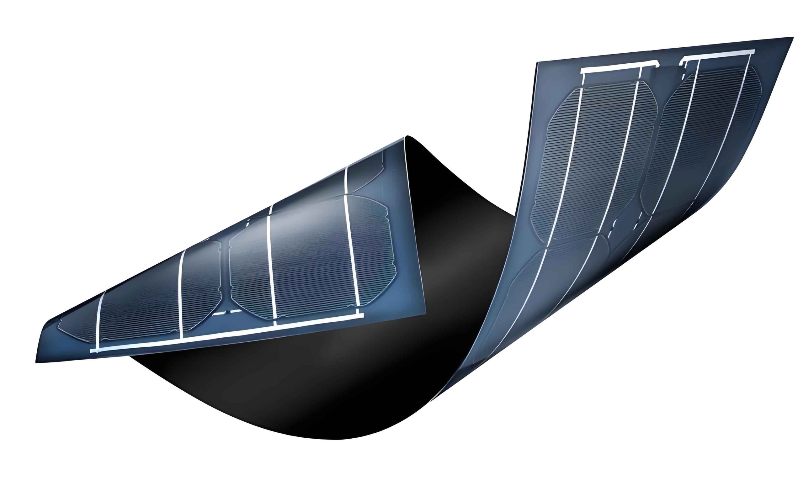
To overcome these limitations, there is a compelling need to explore alternative, non-toxic buffer layer materials with wider bandgaps and favorable band alignment. Ternary alloy Zn1-xMgxO presents an excellent solution. By alloying ZnO (Eg ~3.3 eV) with MgO (Eg ~7.8 eV), a tunable wide bandgap semiconductor is created. The bandgap of Zn1-xMgxO can be continuously adjusted from approximately 3.3 eV to over 4.5 eV by increasing the Mg composition (x), effectively eliminating the short-wavelength absorption loss. More importantly, as the Mg content increases, the electron affinity decreases, allowing for strategic engineering of the band offset at the Zn1-xMgxO/CZTS interface. The goal is to achieve a small positive “spike-like” conduction band offset (0 < ΔEc < 0.4 eV), which can suppress interface recombination while not impeding the flow of electrons from the absorber to the buffer layer, a key requirement for high-efficiency thin film solar panel operation.
While experimental efforts are underway, numerical simulation provides a powerful and cost-effective tool to understand the intricate physics of the heterojunction and guide experimental optimization. In this study, we employ the one-dimensional solar cell simulation software, SCAPS-1D, to comprehensively investigate the performance of a Zn1-xMgxO/CZTS heterojunction thin film solar panel. We focus on the critical parameters governing device performance: the conduction band offset at the heterointerface, the doping concentration of the Zn1-xMgxO buffer layer, and its optimal thickness. Our simulation aims to identify the ideal set of parameters that maximize power conversion efficiency, paving the way for the development of high-performance, cadmium-free CZTS-based thin film solar panels.
Methodology and Simulation Framework
This investigation is conducted using the SCAPS-1D (Solar Cell Capacitance Simulator in one dimension) software, version 3.3.08, developed at the University of Gent. SCAPS-1D numerically solves the fundamental semiconductor equations under steady-state conditions to simulate the electrical characteristics of a thin film solar panel. The core equations solved self-consistently are the Poisson’s equation and the electron and hole continuity equations:
Poisson’s Equation:
$$ \frac{d}{dx} \left( \varepsilon(x) \frac{d\psi}{dx} \right) = -q \left[ p(x) – n(x) + N_D^+(x) – N_A^-(x) \right] $$
Electron Continuity Equation:
$$ \frac{dJ_n}{dx} = q \left( G(x) – R(x) \right) $$
Hole Continuity Equation:
$$ -\frac{dJ_p}{dx} = q \left( G(x) – R(x) \right) $$
Here, $\psi$ is the electrostatic potential, $\varepsilon$ is the permittivity, $q$ is the elementary charge, $n$ and $p$ are the electron and hole densities, $N_D^+$ and $N_A^-$ are the ionized donor and acceptor concentrations, $J_n$ and $J_p$ are the electron and hole current densities, $G$ is the optical generation rate, and $R$ is the net recombination rate (including Shockley-Read-Hall, radiative, and Auger mechanisms).
The standard simulation structure for the thin film solar panel is defined as follows, from the back to the front contact: Metal Back Contact / CZTS Absorber / Zn1-xMgxO Buffer / ZnO Window / Transparent Front Contact. The thickness of the metal contacts is neglected in the simulation. The key material parameters used as input for SCAPS-1D are summarized in Table 1. These parameters are compiled from first-principles calculations, experimental data in the literature, and established values for similar materials, ensuring a realistic simulation baseline for the thin film solar panel.
| Parameter | ZnO (Window) | Zn1-xMgxO (Buffer) | CZTS (Absorber) |
|---|---|---|---|
| Thickness, d (nm) | 200 | Variable (50 default) | 3000 |
| Bandgap, Eg (eV) | 3.3 | Variable (3.9 – 5.35) | 1.5 |
| Electron Affinity, χ (eV) | 4.3 | Variable (4.8 – 3.35) | 4.2 |
| Dielectric Constant, εr | 9 | 9 | 10 |
| CB Effective Density, NC (cm-3) | 2.2×10¹⁸ | 2.0×10¹⁸ | 2.2×10¹⁸ |
| VB Effective Density, NV (cm-3) | 1.8×10¹⁹ | 1.8×10¹⁹ | 1.8×10¹⁹ |
| Doping Type | n-type | n-type | p-type |
| Doping Density, ND/NA (cm-3) | 1×10¹⁸ | Variable (1×10¹⁵ default) | 2×10¹⁵ |
| Electron Mobility, μn (cm²/Vs) | 100 | 100 | 100 |
| Hole Mobility, μp (cm²/Vs) | 25 | 25 | 25 |
| Defect Density (cm-3) | 1.7×10¹⁶ | 1.7×10¹⁶ | 2.7×10¹⁷ |
The defect density in the CZTS absorber is set to a relatively high value of 2.7×1017 cm-3, reflecting the high density of intrinsic point defects (e.g., CuZn and ZnCu antisites) known to exist in kesterite materials. This ensures our simulation models a realistic, non-ideal absorber relevant for current thin film solar panel technology. All simulations are performed under standard AM1.5G illumination at 100 mW/cm² and a temperature of 300 K.
Results and Discussion
1. Influence of Heterointerface Band Alignment
The electronic structure at the buffer/absorber interface is paramount for the performance of any thin film solar panel. The conduction band offset (CBO or ΔEc) is defined as:
$$ \Delta E_c = E_c^{\text{Buffer}} – E_c^{\text{Absorber}} $$
For the Zn1-xMgxO/CZTS system, ΔEc is strongly dependent on the Mg composition (x). Based on the common-anion rule and first-principles calculations, the evolution of key parameters with x is summarized in Table 2.
| Mg Composition (x) | Eg (ZnMgO) (eV) | χ (ZnMgO) (eV) | ΔEc at ZnMgO/CZTS (eV) | Band Alignment Type |
|---|---|---|---|---|
| 0.125 | ~3.90 | ~4.80 | -0.64 | Large Cliff |
| 0.250 | ~4.34 | ~4.40 | -0.20 | Small Cliff |
| 0.375 | ~4.86 | ~3.90 | +0.30 | Small Spike |
| 0.500 | ~5.35 | ~3.35 | +0.85 | Large Spike |
To systematically study its impact, we simulated the thin film solar panel performance while varying ΔEc by adjusting the electron affinity of the buffer layer, keeping all other parameters constant. The results for the key photovoltaic parameters are plotted in Figure 1 and comparative data is shown in Table 3.
For ΔEc < 0 eV (cliff), the performance is severely degraded. A cliff facilitates interface recombination as photogenerated electrons from the CZTS can easily recombine with holes at the interface. This leads to a significant reduction in Voc, fill factor (FF), and consequently, efficiency (η). As ΔEc increases towards and becomes slightly positive (0 to +0.2 eV), we observe a dramatic improvement. The small positive spike acts as a beneficial barrier that repels holes from the interface, drastically suppressing interface recombination. This results in a steep increase in Voc and FF. The short-circuit current density (Jsc) also benefits slightly due to reduced recombination losses.
The peak efficiency for this thin film solar panel configuration is achieved at ΔEc = +0.1 eV, yielding an η of 10.68%. This represents a meaningful improvement over the simulated baseline CdS/CZTS cell (η = 10.26%), primarily due to a higher Voc. However, as ΔEc increases beyond approximately +0.3 eV, Jsc and FF begin to decline sharply. A large spike forms a significant energy barrier for photogenerated electrons attempting to travel from the CZTS absorber into the buffer layer. This barrier increases the series resistance of the device and can lead to carrier blocking, negatively impacting the current collection and the fill factor of the thin film solar panel. This analysis clearly demonstrates that an optimally engineered small positive spike is crucial for high-efficiency, cadmium-free thin film solar panels.
| Buffer Layer (ΔEc) | Voc (mV) | Jsc (mA/cm²) | FF (%) | η (%) |
|---|---|---|---|---|
| CdS (Baseline) | 716.7 | 22.72 | 63.02 | 10.26 |
| ZnMgO (ΔEc = -0.2 eV) | 704.4 | 22.98 | 56.46 | 9.14 |
| ZnMgO (ΔEc = +0.1 eV) | 718.5 | 23.37 | 63.58 | 10.68 |
| ZnMgO (ΔEc = +0.3 eV) | 718.5 | 23.14 | 56.50 | 9.39 |
2. Optimization of Buffer Layer Doping Concentration
The doping density (ND) of the n-type Zn1-xMgxO buffer layer is another critical factor influencing the electric field profile and carrier collection in the thin film solar panel. We investigated its impact by varying ND from 1014 to 1020 cm-3, with a fixed optimal ΔEc of +0.1 eV and buffer thickness of 50 nm.
At very low doping levels (ND < 1016 cm-3), the buffer layer is quasi-intrinsic. The built-in potential and the depletion region width extend significantly into the buffer, but the series resistance is high, and the electric field at the junction may not be strong enough for efficient carrier separation, leading to mediocre performance.
As ND increases from 1016 to 1018 cm-3, all photovoltaic parameters show substantial improvement. The primary reason is the increase in the built-in voltage (Vbi) of the p-n junction, which is approximated by:
$$ V_{bi} \approx \frac{kT}{q} \ln \left( \frac{N_A N_D}{n_i^2} \right) $$
where $n_i$ is the intrinsic carrier concentration. A higher Vbi strengthens the electric field across the depletion region, enhancing the drift-driven collection of photogenerated carriers and reducing recombination losses. This directly translates to higher Voc, Jsc, and FF.
For ND > 1018 cm-3, the performance gains begin to saturate. While a higher Vbi is still beneficial, the depletion region becomes increasingly confined to the absorber layer. In a high-quality absorber with low defect density, this could reduce the volume for carrier generation within the depletion region and potentially increase bulk recombination. However, in our simulation with a high CZTS defect density (2.7×1017 cm-3), the beneficial effect of a stronger field suppressing bulk recombination appears to outweigh any negative effects within this doping range. For practical thin film solar panel fabrication, a buffer layer doping concentration of 1018 cm-3 is identified as an optimal value, providing excellent performance without pushing the limits of dopant incorporation.
3. Optimization of Buffer Layer Thickness
The buffer layer in a thin film solar panel must fulfill two conflicting roles: it must be thick enough to provide complete, pinhole-free coverage of the absorber surface to prevent shunting between the window and absorber layers; and it must be thin enough to be optically transparent, minimizing parasitic absorption. We simulated the device performance with the Zn1-xMgxO thickness varying from 10 nm to 200 nm, with ΔEc = +0.1 eV and ND = 1018 cm-3.
The results indicate a clear trade-off. For very thin buffers (< 30 nm), the performance is slightly lower, which could be attributed to incomplete coverage or increased tunneling-assisted interface recombination. As the thickness increases from 30 nm to about 50-70 nm, the device reaches its peak performance. In this range, the layer is sufficiently thick to form a high-quality heterojunction, and its wide bandgap ensures minimal absorption loss.
For thicknesses beyond 70 nm, a gradual but consistent decrease in Jsc is observed. Although Zn1-xMgxO has a wide bandgap, it is not perfectly transparent. A thicker layer leads to increased parasitic absorption of high-energy photons within the buffer itself before they can reach the CZTS absorber. This reduces the total photon flux available for generating electron-hole pairs in the active layer of the thin film solar panel. Furthermore, a thicker buffer layer may increase the series resistance slightly. Therefore, an optimal thickness window of approximately 40-60 nm is recommended for the Zn1-xMgxO buffer layer, balancing junction quality with optical transparency for maximum efficiency.
Conclusion
In this comprehensive simulation study, we have systematically investigated the potential of Zn1-xMgxO as a high-performance, cadmium-free alternative buffer layer for CZTS-based thin film solar panels using the SCAPS-1D software. Our results underscore the critical importance of precisely engineering the heterojunction interface and buffer layer properties.
We found that the conduction band offset (ΔEc) at the Zn1-xMgxO/CZTS interface is the most decisive factor. A small positive spike in the range of 0 to +0.2 eV is essential to suppress interface recombination and unlock higher open-circuit voltages. A ΔEc of +0.1 eV was identified as the optimal value, yielding a simulated efficiency of 10.68%, outperforming a comparable CdS-buffered structure. Offsets outside this range, either negative (“cliff”) or excessively positive (“large spike”), lead to severe performance degradation due to increased recombination or carrier blocking, respectively.
Furthermore, the doping concentration of the Zn1-xMgxO buffer should be optimized to around 1018 cm-3 to establish a strong built-in electric field for effective carrier collection. The physical thickness of the buffer layer presents a trade-off between junction quality and optical loss, with an optimal range of ~50 nm recommended to ensure full coverage while maintaining high optical transparency for the incident light.
This work provides a clear theoretical roadmap for the experimental development of environmentally friendly Zn1-xMgxO/CZTS thin film solar panels. By targeting a Mg composition (x) that achieves the ideal ΔEc of approximately +0.1 eV (corresponding to x ≈ 0.35-0.40 based on our calculations) and controlling the doping and thickness as outlined, researchers can fabricate buffer layers that mitigate key loss mechanisms. Implementing these design principles is a crucial step towards realizing high-efficiency, non-toxic kesterite thin film solar panels with enhanced performance and sustainability, contributing significantly to the advancement of green photovoltaic technologies.