
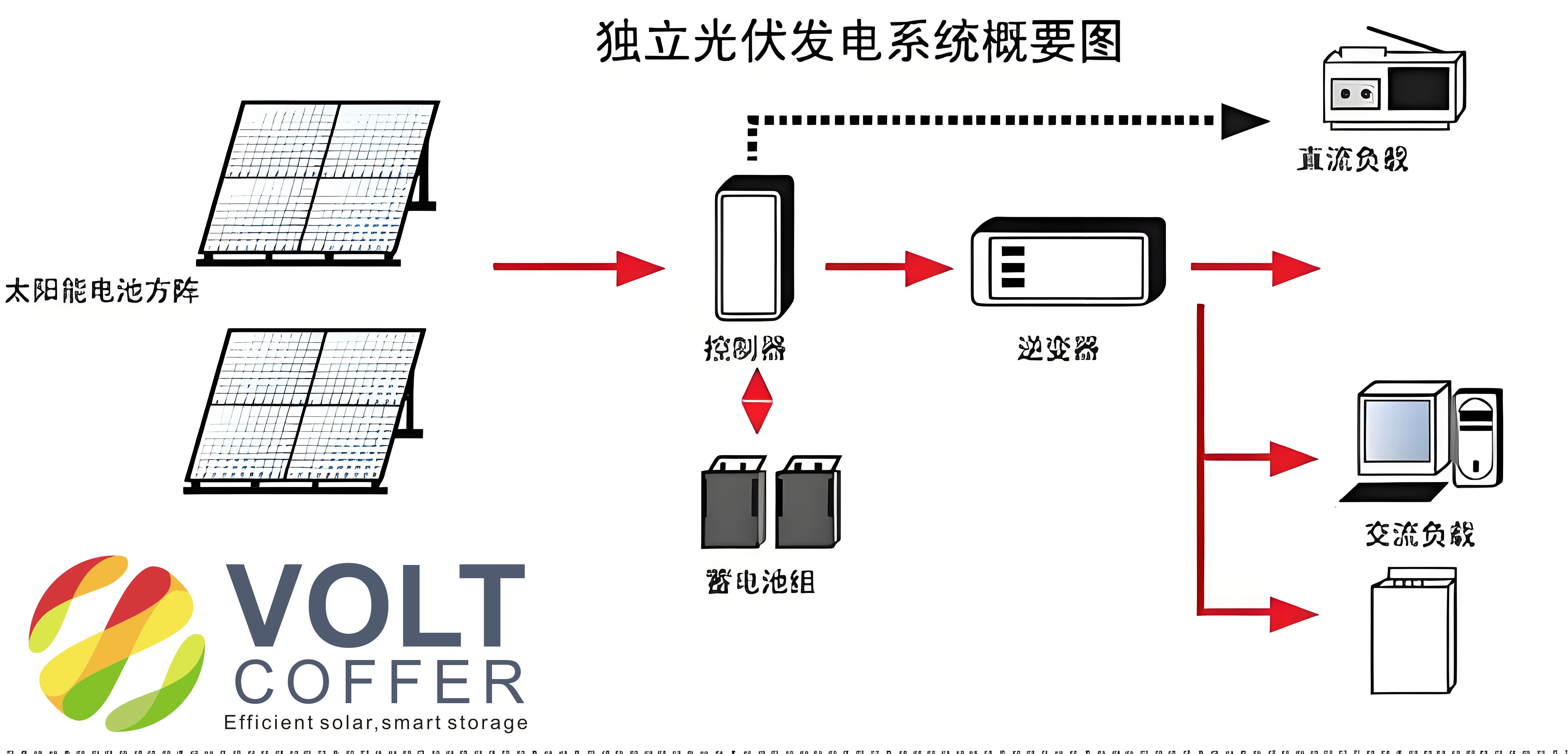
In recent decades, the global energy landscape has undergone significant transformations due to increasing demands and environmental concerns. As a result, renewable energy sources, particularly solar power, have gained prominence. Among various applications, off-grid solar systems have emerged as a reliable solution for remote and standalone power generation. This study focuses on the simulation and analysis of a controller for an off-grid solar system based on a Boost circuit, which is critical for optimizing energy conversion efficiency. The off-grid solar system is designed to operate independently of the main grid, making it ideal for rural areas, emergency power supplies, and portable applications. The core component of such systems is the photovoltaic (PV) array, which converts solar energy into electrical energy, and the DC-DC converter, which regulates the output for practical use. In this context, the Boost circuit serves as a pivotal element in enhancing voltage levels and ensuring stable operation. This article delves into the principles of PV cells, the design of the Boost-based controller, and comprehensive simulation results to validate its feasibility and reliability in off-grid solar systems.
The fundamental operation of a photovoltaic cell relies on the photoelectric effect in semiconductors. When sunlight strikes the PV cell, photons with sufficient energy excite electrons, creating electron-hole pairs. The internal electric field within the PN junction separates these charge carriers, leading to a potential difference across the terminals. This process generates a photocurrent, which can be harnessed for external loads. The electrical characteristics of a PV cell can be modeled using equivalent circuits, which account for various parameters such as series resistance, shunt resistance, and temperature effects. The output current-voltage (I-V) relationship is governed by the following equation, derived from the diode equation:
$$I_{RL} = I_{ph} – I_{os} \left[ \exp\left(\frac{q}{AKT}(V_{RL} + I_{RL}R_s)\right) – 1 \right] – \frac{V_{RL} + I_{RL}R_s}{R_{sh}}$$
where \(I_{RL}\) is the output current, \(I_{ph}\) is the photocurrent proportional to solar irradiance, \(I_{os}\) is the reverse saturation current, \(q\) is the electron charge (approximately \(1.602 \times 10^{-19}\) C), \(A\) is the ideality factor (typically 1.5 for silicon cells), \(K\) is Boltzmann’s constant (\(1.38 \times 10^{-23}\) J/K), \(T\) is the absolute temperature in Kelvin, \(R_s\) is the series resistance, \(R_{sh}\) is the shunt resistance, and \(V_{RL}\) is the output voltage. This equation highlights the nonlinear nature of PV cells, which necessitates advanced control strategies to maximize power extraction. In off-grid solar systems, maintaining optimal operation under varying environmental conditions is crucial, and the Boost circuit plays a key role in achieving this by adjusting the duty cycle to track the maximum power point (MPP).
The Boost circuit, also known as a step-up converter, is essential in off-grid solar systems for elevating the PV array’s output voltage to levels suitable for battery charging or inverter input. Its operation involves an inductor, a switch (typically a MOSFET or IGBT), a diode, and a capacitor. When the switch is closed, the inductor stores energy from the PV array, and when the switch is open, the inductor releases energy, resulting in a higher output voltage. The voltage conversion ratio is given by:
$$V_{out} = \frac{V_{in}}{1 – D}$$
where \(V_{in}\) is the input voltage from the PV array, \(V_{out}\) is the output voltage, and \(D\) is the duty cycle of the switch. This relationship demonstrates that by controlling \(D\), the output voltage can be regulated efficiently. For an off-grid solar system, the Boost circuit must integrate with a maximum power point tracking (MPPT) algorithm to ensure that the PV array operates at its MPP under changing irradiance and temperature. Common MPPT techniques include Perturb and Observe (P&O) and Incremental Conductance, which adjust the duty cycle dynamically. The design of the controller involves selecting appropriate components to minimize losses and enhance reliability. For instance, the inductor value \(L\) can be calculated based on the desired ripple current and switching frequency \(f_s\):
$$L = \frac{V_{in} \cdot D}{\Delta I_L \cdot f_s}$$
where \(\Delta I_L\) is the peak-to-peak inductor current ripple. Similarly, the output capacitor \(C\) is sized to limit voltage ripple:
$$C = \frac{I_{out} \cdot D}{\Delta V_{out} \cdot f_s}$$
where \(I_{out}\) is the output current and \(\Delta V_{out}\) is the allowable output voltage ripple. These equations are critical for designing a robust Boost converter for off-grid solar systems, ensuring stable performance across various operating conditions.
To validate the controller design, a simulation model was developed using MATLAB/Simulink, representing a typical off-grid solar system configuration. The model includes a PV array block, a Boost converter block, an MPPT controller, and a resistive load. The PV array was parameterized based on standard monocrystalline silicon cells, with key specifications summarized in Table 1. The simulation parameters were chosen to reflect real-world scenarios, such as varying irradiance from 200 W/m² to 1000 W/m² and temperature fluctuations from 25°C to 50°C. The Boost converter operated at a switching frequency of 20 kHz, with components selected to achieve high efficiency and minimal ripple.
| Parameter | Value | Unit |
|---|---|---|
| Maximum Power (Pmax) | 100 | W |
| Open-Circuit Voltage (Voc) | 22.5 | V |
| Short-Circuit Current (Isc) | 5.8 | A |
| Voltage at MPP (Vmpp) | 18.0 | V |
| Current at MPP (Impp) | 5.56 | A |
| Series Resistance (Rs) | 0.05 | Ω |
| Shunt Resistance (Rsh) | 1000 | Ω |
The MPPT controller implemented the P&O algorithm, which periodically perturbs the duty cycle and observes the change in output power to converge towards the MPP. The algorithm’s effectiveness was evaluated under dynamic conditions, such as sudden changes in solar irradiance. The simulation results captured the transient and steady-state behavior of the off-grid solar system, including output voltage, current, and power. For instance, the PV array’s output voltage stabilized between 16 V and 22 V, while the current ranged from 3 A to 4 A, as shown in the I-U-P characteristics. The Boost converter successfully elevated the voltage to approximately 48 V for battery charging, with minimal overshoot and ripple.
Further analysis involved evaluating the efficiency of the Boost converter and the overall off-grid solar system. Efficiency \(\eta\) is defined as the ratio of output power to input power:
$$\eta = \frac{P_{out}}{P_{in}} \times 100\%$$
where \(P_{in}\) is the power from the PV array and \(P_{out}\) is the power delivered to the load. The simulation results indicated an average efficiency of 94.5% under standard test conditions (irradiance of 1000 W/m² and temperature of 25°C). This high efficiency is attributed to the optimized component selection and effective MPPT. Additionally, the output power stability was assessed using the coefficient of variation (CV), calculated as:
$$CV = \frac{\sigma_{P_{out}}}{\mu_{P_{out}}} \times 100\%$$
where \(\sigma_{P_{out}}\) is the standard deviation of output power and \(\mu_{P_{out}}\) is the mean output power. The CV was found to be less than 2%, demonstrating reliable performance in the off-grid solar system. Table 2 summarizes the key performance metrics from the simulation.
| Metric | Value | Unit |
|---|---|---|
| Average Output Voltage | 48.2 | V |
| Average Output Current | 2.08 | A |
| Maximum Output Power | 100.3 | W |
| Efficiency (η) | 94.5 | % |
| Voltage Ripple (ΔVout) | 0.5 | V |
| Current Ripple (ΔIL) | 0.3 | A |
| MPPT Tracking Accuracy | 98.7 | % |
The simulation also investigated the response of the off-grid solar system to fault conditions, such as partial shading or load variations. In such scenarios, the Boost converter with MPPT maintained stable operation by adjusting the duty cycle rapidly. For example, when irradiance dropped by 50%, the output power decreased smoothly without abrupt transitions, protecting the load from damage. The controller’s ability to handle these dynamics underscores its suitability for real-world off-grid solar systems, where environmental factors are unpredictable.
In conclusion, this study demonstrates the effectiveness of a Boost circuit-based controller in off-grid solar systems through detailed simulation and analysis. The principles of photovoltaic energy conversion were elaborated with mathematical models, and the Boost converter design was validated for its ability to enhance voltage and maintain efficiency. The simulation results confirm that the controller achieves reliable maximum power point tracking, high efficiency, and stable operation under varying conditions. Future work could explore hybrid topologies or advanced MPPT algorithms to further improve performance. Overall, the Boost circuit proves to be a feasible and reliable solution for DC-DC conversion in off-grid solar systems, contributing to the advancement of sustainable energy technologies.
Moreover, the integration of energy storage elements, such as batteries, into the off-grid solar system was considered in the simulation. The Boost converter’s output was connected to a battery bank through a charge controller, which regulated the charging current and voltage to prevent overcharging or deep discharge. The battery state of charge (SOC) was modeled using the following equation:
$$SOC(t) = SOC_0 + \frac{1}{C_{bat}} \int_0^t I_{bat}(\tau) d\tau$$
where \(SOC_0\) is the initial state of charge, \(C_{bat}\) is the battery capacity in ampere-hours, and \(I_{bat}\) is the battery current. The simulation showed that the Boost converter maintained a constant voltage during bulk charging, ensuring efficient energy transfer to the battery. This aspect is crucial for off-grid solar systems, as it prolongs battery life and enhances system reliability.
Additionally, the impact of temperature on the off-grid solar system was analyzed. The PV array’s output decreases with rising temperature due to reduced open-circuit voltage. The temperature coefficient for voltage \(\beta\) was incorporated into the model:
$$V_{oc}(T) = V_{oc,STC} + \beta (T – T_{STC})$$
where \(V_{oc,STC}\) is the open-circuit voltage at standard test conditions (25°C), and \(T_{STC}\) is the standard temperature. The simulation results indicated that the Boost converter compensated for this drop by adjusting the duty cycle, thereby maintaining the output power within acceptable limits. This adaptability is essential for off-grid solar systems deployed in regions with high temperature variations.
Furthermore, the economic and environmental benefits of off-grid solar systems were briefly discussed. By reducing reliance on fossil fuels, these systems lower greenhouse gas emissions and operational costs. The Boost-based controller enhances this by improving energy conversion efficiency, which translates to higher energy yield over the system’s lifetime. For instance, in remote applications, such as telecommunications or water pumping, the off-grid solar system with a Boost controller can provide uninterrupted power with minimal maintenance.
In summary, the simulation study comprehensively validates the Boost circuit as a key component in off-grid solar systems. The controller’s design, based on mathematical models and practical considerations, ensures optimal performance across diverse scenarios. As solar technology continues to evolve, innovations in converter topologies and control strategies will further enhance the capabilities of off-grid solar systems, making them a cornerstone of global renewable energy efforts.