
Solar grid connected power generation is a good way to save investment and solve the problem of solar power generation. The entire solar grid connected power generation system involves a wide range of knowledge, and the essential conversion component in the system, the inverter, has a complex working principle. This inverter is mainly used to solve the problem of green energy grid connected energy transmission, converting solar energy into AC power. Although there are also dedicated inverters that convert batteries into AC power to meet user specific requirements, specifically designed for converting DC to AC power. But the application scenarios of the two are different, with significant differences in functionality and performance, and cannot be generalized. Therefore, the universality of specialized inverters as teaching experimental instruments is poor, and there are significant deficiencies in understanding the concepts of grid connected and off grid power generation; Moreover, it is almost impossible to work off the grid with analog DC power sources, and non grid connected inverters cannot also work on the grid. In addition, it is not easy to adjust various parameters of the two inverters, and the circuit is complex, making it difficult to balance universality. At present, there are no specialized devices for simulating solar grid connected power generation for teaching or practical training in the market. Therefore, this article designs a simulated solar grid connected power generation device that can be widely used in university electrical laboratories to solve related teaching and training problems.
1. Composition of a simulated solar grid connected power generation device
The system consists of an input processing unit, a variable voltage unit, a rectification and filtering unit, and an inverter. After being processed by an input processing unit, a variable voltage unit, a rectification and filtering unit, the municipal electricity outputs adjustable direct current to simulate the power generation of solar panels affected by sunlight; The DC power is then connected to the grid for power generation through the inverter control circuit. During grid connected operation, operating the frequency converter cannot change the grid frequency, and the input grid power can only be changed by changing the angle between the grid voltage U and the merged voltage E. The power input to the power grid is:
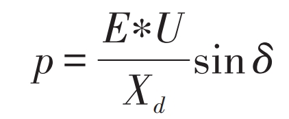
In the formula: p is the power input to the power grid; Xd is the equivalent impedance of grid connection; δ The phase shift angle generated by the phase shift circuit. It is possible to simulate grid connected power generation by changing the output status of the inverter by changing the input of the analog circuit.
2. Design of a controller for simulating solar grid connected power generation devices
The schematic diagram of the device circuit is shown in the figure.
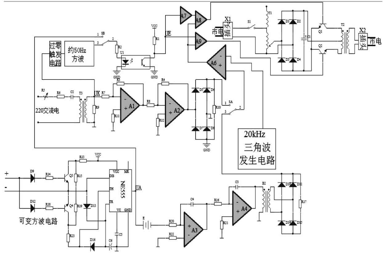
The solar inverter controller circuit in the figure includes a mains supply, a built-in sine wave generation circuit, and a phase shift circuit connected to the mains supply signal. The sine wave generation circuit has a frequency conversion function. The municipal electrical signal and the built-in sine wave generation circuit signal are connected to the modulation circuit through a switching circuit, and modulated with high-frequency triangular waves; The modulated signal is output through a branch output processing circuit, outputting two SPWM pulse signals with opposite phases. This pulse signal can be controlled by the mains phase shift signal or by a sine wave generation circuit with frequency conversion function; The changing pulse is sent to the inverter control main circuit, which can change various conditions of the inverter and simulate grid connection under various conditions.
3. Simulate the working principle of solar grid connected power generation devices
The working principle of a simulated solar grid connected power generation device is as follows: the plug is connected to the mains power, and the 220V mains power is connected through an adjustable voltage transformer. After being rectified and filtered, the adjustable DC power is output, changing the DC side voltage of the inverter, and simulating the power generation status of the solar panel.
The mains power is supplied through a phase-shifting circuit composed of potentiometer R1, resistor R2, capacitor C2, current transformers B1 and R3. The signal is amplified by operational amplifiers A1 and A2, and a 100 Hz sine wave half wave signal is generated through a single-phase rectifier bridge.
The NE555 circuit generates a variable square wave circuit, which forms a triangular wave signal with the DC power supply E through an integral unit composed of an operational amplifier A3, and then forms a sine wave signal through an integral unit composed of an operational amplifier A4. The variable frequency sine wave half wave signal is also formed through a transformer B2 and a single-phase rectifier bridge.
The municipal 100 Hz sine wave half wave signal and the frequency conversion sine wave half wave signal generated by the machine are transmitted to the operational amplifier A6 through the switching switch SA and modulated with the high-frequency triangular wave signal to generate the corresponding SPWM signal of the sine wave half wave. At the same time, the UK point of the mains signal passes through a zero crossing trigger circuit, generating a 50 Hz square wave signal. The variable frequency square wave signal of this machine is sent to the UA point and sent to the SB switch, and a synchronous signal is generated at the UE point through the optoelectronic coupling circuit. One channel of this signal is directly connected to the SPWM signal and the gate, while the other channel is inverted and then connected to the SPWM signal and the gate, resulting in two signals. This pulse signal can be controlled by the mains phase shift signal or by a sine wave generation circuit with variable frequency function. The changed pulse is sent to the inverter main circuit to change various output conditions of the inverter, thus achieving simulated grid connected power generation.
4. Application of simulated solar grid connected power generation devices
The solar inverter control circuit involved in this device can be applied to simulate grid connected power generation teaching in university electrical laboratories. Students can understand various situations of simulated grid connected power generation by changing various parameters:
1) In the no-load state, when using the built-in variable frequency sine wave generator circuit, changing the input voltage of the variable square wave circuit changes the output frequency of the inverter: This can help students understand the frequency changes of grid connected power generation.
2) In the no-load state, by changing the output voltage of the adjustable voltage transformer, the AC voltage amplitude of the inverter output is changed: it can help students understand the voltage amplitude changes of grid connected power generation.
3) After the inverter is connected to the grid through quasi synchronous method, changing the input voltage of the variable square wave circuit changes the active power input to the grid by the inverter: this can help students understand the changes in active power generated by grid connection.
4) After grid connection, changing the output voltage of the adjustable voltage transformer, that is, changing the reactive power input of the inverter into the grid, can help students understand the changes in reactive power generated by grid connection.
Changing various parameters when simulating grid connected power generation using municipal electrical signals facilitates changing the operating status of the inverter. This has strong practical operability for students to understand the various states of green energy grid connection operation, and can improve their understanding level. In addition, this inverter can also be directly applied to inverters matched with various green energy sources.
5. Conclusion
This design simulates a solar grid connected power generation device that can adjust parameters in the laboratory and can be widely used in university laboratories to simulate solar grid connected power generation. Students can experiment anytime and anywhere, without being affected by weather conditions, effectively solving the problem of solar panel installation site, without the need to purchase and maintain solar panels, saving costs, and having great significance for teaching and training.