
Since the goal of carbon neutrality and carbon peaking was proposed, building a new type of power system with new energy as the main body has become a new direction for the reform of the power industry. The output of clean energy, mainly photovoltaic and wind power, is uncertain, and the introduction of a large number of new energy sources into the power system will further reduce the stability of the power system. Introducing energy storage systems into the power system can not only improve the utilization rate of new energy, but also assist traditional thermal power units in peak shaving and frequency regulation, reducing the instability caused by the large-scale grid connection of new energy sources to the power system.
By using energy storage devices, energy can be shifted at a time level, but the high single investment and long cost recovery period of energy storage systems are not conducive to the development of user side energy storage. In recent years, domestic and foreign scholars have proposed a shared energy storage model in response to this situation. Propose a shared energy storage model that separates ownership and usage rights of the energy storage system. Energy storage service providers are responsible for investing in and constructing energy storage devices, and leasing energy storage resources to users with energy storage needs. Propose three business models for energy storage systems in response to China’s energy storage environment, and analyze the profit model of shared energy storage power stations. The concept of cloud energy storage was proposed, and the application of shared energy storage in distributed energy storage was introduced. Propose a dual layer optimization configuration method for shared energy storage power stations serving multiple microgrid systems, and conduct preliminary research on shared energy storage configuration. Propose a user side distributed shared energy storage model, further improving the details of the shared energy storage operation plan. The above research has studied the economic benefits and operating methods of the shared energy storage business model, demonstrating the enormous commercial potential of the shared economy model in the energy storage industry. However, the model used is relatively ideal and does not consider the potential capacity loss of energy storage batteries during actual operation.
Without considering the capacity degradation of energy storage batteries, the shared energy storage mode can significantly improve the utilization rate of energy storage. However, the continuous decline in the health status of energy storage batteries during their operation period will have a significant impact on the economic benefits of energy storage stations. Through simulation calculations, analysis shows that at the end of operation, the remaining energy storage capacity is already less than 30% of the initial capacity, greatly affecting the profitability of shared energy storage, It is necessary to consider the attenuation of the health status of energy storage batteries during their operating years in the initial stage of configuration.
At present, lithium iron phosphate batteries using lithium iron phosphate as the active substance have various advantages such as high energy density and low production cost, making them the most widely used solution for commercial energy storage. There is a large amount of research focused on the estimation of the lifespan of such batteries. By fitting the relationship between the changes in battery health status and the number of cycles under different discharge depths through experiments, a life loss model for lithium iron phosphate batteries is established. Using the rain flow method to estimate battery life and study the optimization of the operation of energy storage stations in commercial parks. We evaluated the energy storage life loss during operation and proposed a two-layer optimization model for microgrid energy storage capacity that takes into account the economic operation of the system. A hybrid optimization model for battery energy storage configuration was established considering the full life cycle cost of the energy storage system.
The above research on the changes in the health status of traditional energy storage batteries has been relatively complete, but the research objects are mostly distributed independent energy storage systems. There is relatively little research on the impact of changes in battery health status on configuration under shared energy storage mode.
Based on the current situation, research on shared energy storage is still in its infancy. Therefore, this article uses the rainflow method to analyze the changes in the health status of energy storage batteries under the shared energy storage service mode, and establishes a configuration model for shared energy storage power stations based on double-layer programming. The outer model solves the configuration problem of energy storage power stations considering battery capacity decay, while the inner model solves the optimization operation problem of multiple microgrids with shared energy storage participation. The Karush Kuhn Tucher (KKT) method is used to transform the model for solution. Finally, a numerical example is set up to validate and analyze the model.
1.Shared Energy Storage Power Station Service CCHP System Operation Mode
The combined cooling heating and power (CCHP) system is a micro energy grid system that integrates power supply, cooling, and heating capabilities. A typical CCHP system utilizes wind and solar energy to supply electricity, heat, and cold energy to users. However, independent CCHP systems, due to their small scale and strong load uncertainty, often experience wind and light abandonment, resulting in relatively strong energy storage needs. Moreover, CCHP systems have a small volume and lack the ability to independently configure energy storage systems. So introducing shared energy storage between multiple independent CCHP systems can fully utilize the advantages of shared economy.
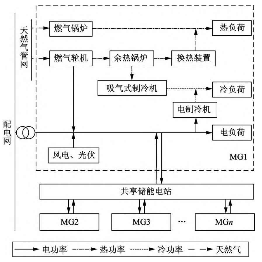
The CCHP system analyzed in this article consists of gas turbines, gas boilers, wind power, photovoltaics, and refrigeration and heating equipment. The connection between the CCHP system and the shared energy storage power station is shown in Figure 1, where MG represents each CCHP system and the lines represent the direction of energy flow. The system can purchase electricity and natural gas from the outside, and there is a flow of hot and cold electricity energy inside each system, which is connected to a shared energy storage station separately. Shared energy storage operators invest in the construction of energy storage systems, and each CCHP system follows the scheduling of the power station. They sell electricity to the power station when their own power is surplus, and purchase electricity from the power station when their own power is insufficient. Due to relevant policy restrictions, the CCHP system cannot reverse power transmission to the power grid, and there is no power exchange between the shared energy storage station and the power grid.
The shared energy storage power station achieves profitability by utilizing the price difference between charging and discharging, as well as by charging service fees to the connected CCHP system. When there is a power exchange between the power station and the system, a service fee will be charged based on the size of the exchange power. The power station purchases electricity from CCHP users at a certain purchase price during low load periods, and sells electricity at a price lower than the selling price of the grid during peak load periods. This guides users to purchase electricity from shared energy storage stations during peak load periods, saving on peak electricity price costs, and selling electricity to shared energy storage stations during low load periods, promoting daily charging and discharging balance of energy storage stations.
Due to the non simultaneity of the load peaks of each CCHP system, when two CCHP systems require charging and discharging services respectively, the actual power flow is from one system to another, but nominally it is a shared energy storage station that achieves power exchange with the two systems separately. By operating in this way, the rated power of the shared energy storage power station configuration can be reduced, the charging and discharging frequency can be greatly reduced, and the service life of the power station can be extended.
2. Life characteristics of shared energy storage power plants
The state of health (SOH) of a battery is an important indicator that characterizes the ratio of the remaining capacity to the initial capacity of the battery. The capacity of an energy storage battery will continuously decline during its normal life cycle, and battery life loss should be calculated when optimizing configuration. The service life of a battery is related to factors such as its charging and discharging depth, number of cycles, operating temperature, and charging and discharging rate. Due to the fact that energy storage stations are generally equipped with effective temperature control measures and the designed charging and discharging rate is within a reasonable range, this article only considers the impact of battery charging and discharging depth and number of cycles on battery life.
To analyze the changes in battery SOH, it is necessary to calculate the number of battery cycles at different discharge depths (DOD) and quantify them based on statistical fitting. This article uses the commonly used rain flow counting method in fatigue analysis to calculate the depth of battery charging and discharging, and provides a detailed introduction to the rain flow method. The process of calculating the number of cycles under different DODs (represented by HDOD) using the rainflow method is shown in Figure 2.
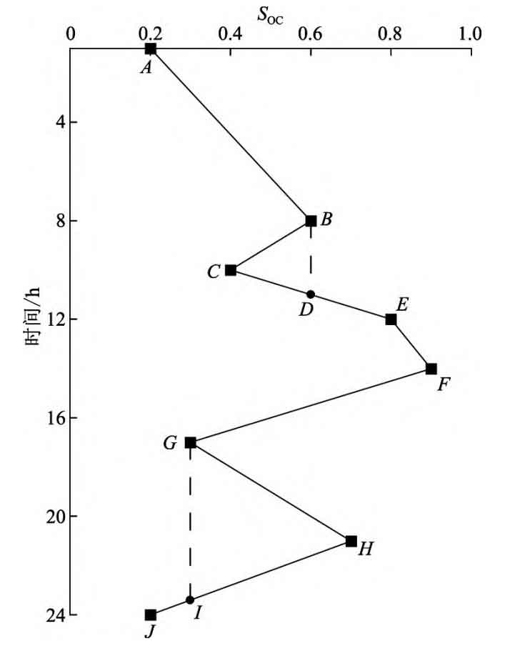
Rotate the state of charge (SOC) curve of the battery clockwise by 90 °, and raindrops flow down from point A to point D when they reach point B, and then flow through point E to point F, forming an ABDEF half cycle. The second raindrop flows from point B to point C. As point F has a larger peak than point B, the raindrop stops at point C, forming a BC half cycle. The third raindrop flows down from point C and ends at point B, forming a CD half cycle. By analogy, we obtain FGIJ semi cycle, GH semi cycle, and HI semi cycle. Merge the half loop to obtain the ABDEFGIJ loop
The corresponding charging and discharging depths for BCD cycle and GHI cycle are the difference in SOC between AF, BC, and GH, respectively. The SOC range is [10%, 90%], so the DOD range is [0, 80%]. The corresponding relationship between SOH and the number of cycles can be fitted through experimental testing. Through testing, a cubic function is used for fitting, and the corresponding relationship between SOH and the number of cycles n under different DODs is obtained as follows:
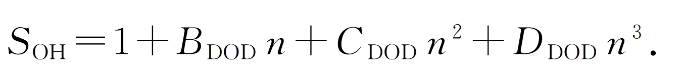
In the formula, BDOD, CDOD, and DDOD are the experimental fitting values, which are coefficients of 1-3 terms, respectively.
According to the rain flow method, calculate the SOH of energy storage batteries. The principle is to convert the number of cycles at low discharge depths to the number of cycles corresponding to high discharge depths, and finally obtain the battery SOH that is discharged multiple times under complex SOC curves. The specific steps are as follows:
a) Divide the DOD values into three intervals: [0, 40%], (40%, 60%], and (60%, 80%). Record the number of cycles within these three intervals as n40, n60, and n80, respectively. Equivalent the DOD of discharge cycles within these three intervals to 40%, 60%, and 80%, respectively;
b) Bring n=n40 into the 40% DOD corresponding curve to obtain the SOH fitting value of the energy storage battery η SOH40;
c) Will η Substitute SOH40 into the 60% DOD curve to invert the number of cycles n ′ 40. Equivalent 40% DOD to 60% DOD cycles, add n ′ 40 and n60 to obtain the total number of cycles converted to 60% DOD. Substitute into the 60% DOD curve to obtain η SOH60;
d) Repeat the above process to obtain η SOH80, now that the total number of cycles has been converted to 80% DOD, then η SOH80 is the end of year energy storage battery SOH.
The remaining capacity of energy storage batteries at the end of the year:
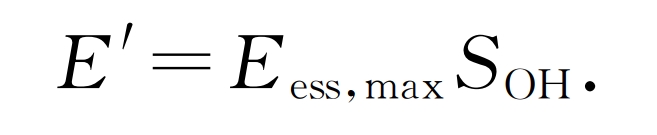
In the formula, Eess and max are the rated capacity of the energy storage battery configuration.
3. Double layer optimization model
Bilevel programming is an optimization problem with a two-level system, with one optimization objective and corresponding constraint conditions for the inner and outer layers. The outer layer problem relies on the decision quantity of the inner layer problem, and the decision quantity of the inner layer problem is influenced by the decision quantity of the outer layer problem. The two layers of problems are coupled with each other. The significance of bilevel programming lies in its ability to prioritize starting from the outer problem and finding the optimal value of the inner problem based on the decision-making of the outer problem. In this example, the outer model is used to solve the shared energy storage configuration problem, while the inner model is used to solve the annual operation mode problem of the microgrid.
3.1 External Shared Energy Storage Configuration Model
In the outer optimization model, the energy storage power station is configured based on relevant parameters such as the operation of the microgrid, where the decision variables are the capacity and maximum charging and discharging power of the energy storage power station. Select an appropriate design operating period and consider the impact of annual changes in SOH of energy storage batteries on battery capacity. The optimization goal is to have the lowest average annual operating cost within the design operating period.
3.1.1 Optimization objective function of outer model
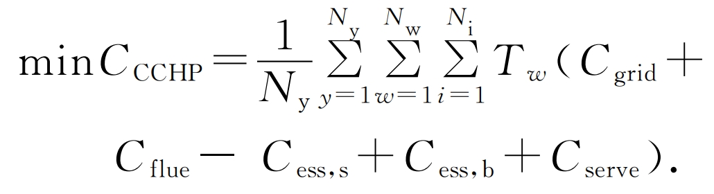
The objective function for optimizing the outer model is:
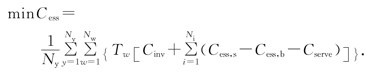
In the formula: Cess is the annual operating cost of the shared energy storage power station; Ny is the designed operating life of the energy storage power station; Cinv is the daily average investment and daily operating cost of the energy storage power station; Nw is the typical number of days with different electricity consumption characteristics within a year; Tw is the corresponding number of days in a year for each typical day; Ni is the number of CCHP systems; Cess is the daily cost of purchasing electricity from the CCHP system for the shared energy storage power station; Cess, b is the daily cost of purchasing electricity from the shared energy storage station for the CCHP system; Cserve charges a service fee from the CCHP system for shared energy storage power stations.
a) Cost model for shared energy storage power plants. When calculating the cost of shared energy storage power stations, in order to consider the time value of funds, the one-time investment is converted to an equal annual value, and the expression is as follows:
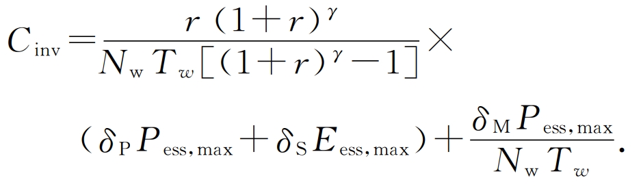
In the formula: r is the annual interest rate of the fund; γ Is the life cycle of the device; δ P is the investment cost per unit power; δ S is the unit investment capacity cost; δ M is the maintenance cost per unit power; Pess, max, Eess, max are the maximum charging and discharging power and maximum capacity of the shared energy storage station, respectively.
b) Daily cost of purchasing electricity from CCHP system for shared energy storage power stations
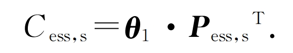
In the equation: θ 1 is the electricity price matrix for CCHP system to sell electricity to energy storage power stations during different scheduling periods; Pess, s is the power matrix for selling electricity to energy storage stations during different scheduling periods on typical days of the system.
c) Daily revenue from selling electricity from shared energy storage power stations to microgrids
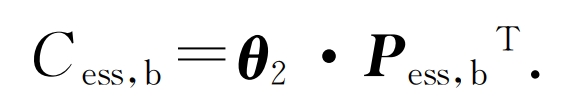
In the equation: θ 2 is the electricity price matrix for the CCHP system to purchase electricity from energy storage stations during different scheduling periods; Pess, b is the power matrix for purchasing electricity from energy storage stations during different scheduling periods on typical days of the system.
d) Collection of service fees for shared energy storage power stations
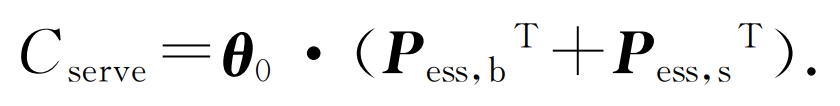
In the equation θ 0 is the matrix of unit power service fees collected from energy storage stations during different scheduling periods on typical days of the system.
3.1.2 Limitations of Outer Model
a) Energy multiplier constraints for energy storage power plants. The rated capacity and rated power of energy storage power stations are limited by the energy ratio of energy storage batteries, which is manifested as a proportional relationship, namely:
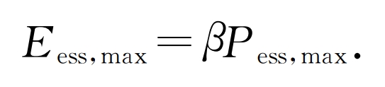
In the equation β Is the energy rate of the energy storage battery.
b) The state of charge constraints for energy storage power plants are:
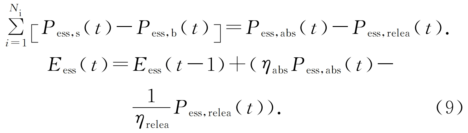
In the formula: Pess, s (t) is the typical daily power sold to the energy storage station during the scheduling period of the system; Pess, b (t) refers to the typical daily scheduling period of the system when purchasing power from energy storage stations; Eess is the state of charge of the shared energy storage power station during a certain scheduling period; η ABS η Release refers to the charging and discharging efficiency; Pess, ABS, Pess, and release respectively represent the charging and discharging power of the shared energy storage power station during the scheduling period.
c) Power constraints for charging and discharging of energy storage stations. The charging and discharging power of the energy storage power station should be less than the rated value, and the power station cannot charge and discharge simultaneously during the same scheduling period. The constraints are as follows:
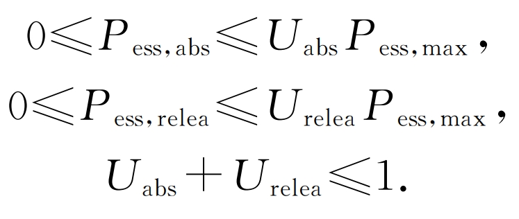
In the formula, Uabs and Urelease are the charging and discharging identification bits, both of which are Boolean variables.
d) Limitations on the lifespan loss of energy storage batteries. Energy storage batteries will age with increasing operating time, specifically manifested as the battery capacity continuously decreasing during the design operating life. When solving, the battery capacity should be corrected, namely:
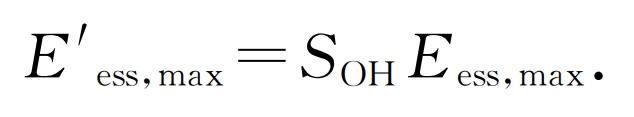
In the formula, E ‘ess, max is the corrected capacity of the energy storage battery for the following year.
3.2 Inner layer CCHP optimization operation model
The inner model is used to solve the operation problems of the CCHP system, and its results are influenced by the decision variables of the outer model. This article adopts the CCHP system configuration method, which needs to consider the cooling, heating, and electricity
Power balance, upper and lower limits of equipment output, power limit for CCHP system to purchase electricity from the grid, and power exchange limit with shared energy storage stations.
3.2.1 Inner layer model optimization objective function
The inner objective function is the lowest annual operating cost of the CCHP system, which is:
Among them, the daily cost of purchasing electricity from the power grid for the CCHP system is:
In the equation: θ 3 is the electricity price matrix for CCHP to sell electricity to energy storage stations during different scheduling periods; Pgrid is the power matrix for purchasing electricity from the power grid during different scheduling periods on typical days of the system.
Daily gas cost of CCHP system:
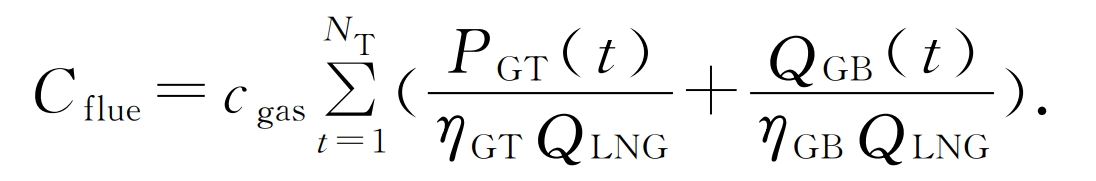
In the formula: NT is the number of typical daily scheduling periods; Cgas is the price of natural gas, yuan/m3; PGT (t) is the output power of the gas turbine during the typical daily scheduling period of the system; QGB (t) is the output power of the gas boiler during the typical daily scheduling period of the system; η GT η GB represents the efficiency of gas turbines and gas boilers respectively; QLNG is the calorific value of natural gas.
3.2.2 Constraints of Inner Model
a) The power balance constraints of the CCHP power supply system are:

In the formula, PPV and PWD represent the typical daily photovoltaic and wind power output power matrices of the system during different scheduling periods; PEC represents the power consumption matrix of electric refrigerators during different scheduling periods of typical days in the system; PLD is a typical daily electricity load matrix for different scheduling periods in the system.
b) The power balance constraints of the CCHP cooling system are:
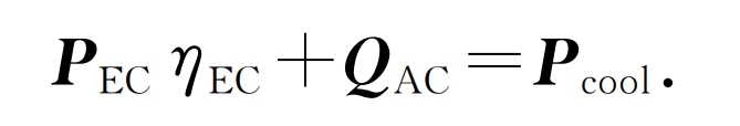
In the equation: η EC is the energy efficiency ratio of the electric refrigerator; QAC is the output matrix of the aspirated chiller for different scheduling periods on typical days of the system; Pcool is the cooling load power matrix for typical daily different scheduling periods of the system.
c) The power balance constraints of the CCHP heating system are as follows:
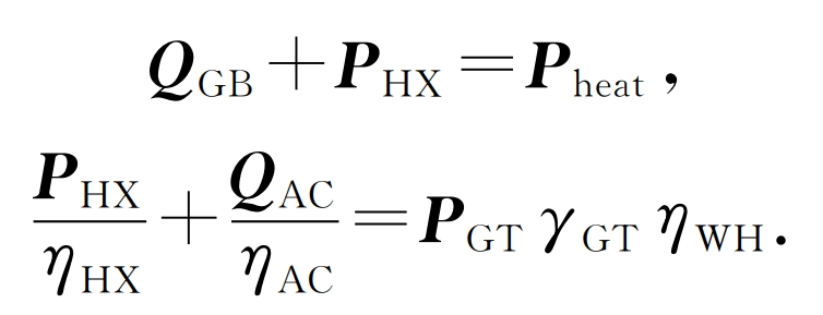
In the formula: PHX is the typical output thermal power matrix of the system’s heat exchange device during different scheduling periods; Pheat is the heat load power matrix for different scheduling periods of typical days in the system; η HX η AC refers to the efficiency of the heat exchange device and the efficiency ratio of the suction refrigeration system; γ GT is the thermoelectric ratio of the gas turbine; η WH is the efficiency of the waste heat boiler.
d) The output constraints of each equipment in the CCHP system are as follows:
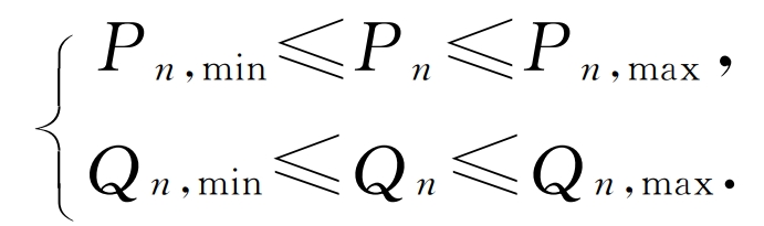
In the formula, Pn and Qn respectively represent the output electrical power and cold and hot power of the equipment; Pn, min, Pn, max are the lower and upper limits of the electrical power of the system equipment during each scheduling period; Qn, min, Qn, max are the lower and upper limits of the cold and hot power output of the system equipment during each scheduling period.
e) The constraints for the CCHP system to purchase electricity from the power grid are:
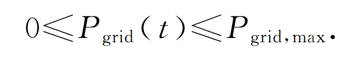
In the formula: Pgrid (t) is the typical daily power purchased from the power grid during the dispatch period of the system; Pgrid, max is the upper limit value of the system’s electricity purchase from the power grid during each scheduling period.
f) The energy exchange constraints between the CCHP system and the shared energy storage plant are as follows:
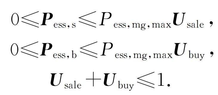
In the formula, Usale and Ubuy are the energy interaction state bit matrices between the system and the shared energy storage station during each scheduling period; Pess, mg, max are the maximum exchange power between the system and the shared energy storage power station.
4 Model Transformation and Solution
In the two-layer optimization model constructed above, the inner and outer layer problems are coupled and difficult to directly solve. The commonly used method for solving double-layer optimization models is to convert double-layer optimization into single-layer optimization. Considering that the inner layer problem is convex, continuous, and differentiable, this article uses the KKT method to transform the model. By utilizing the complementary relaxation conditions of KKT, the optimization objectives and constraints of the inner model are transformed into additional constraints of the outer model. Then, the nonlinear conditions in the constraints are linearized using the large M method to obtain a single-layer linear programming model. The YALMIP toolbox on the MATLAB platform can be used for modeling, and the commercial solver CPLEX can be called to solve the energy storage configuration problem.
When solving, it is necessary to consider the impact of battery capacity attenuation on the configuration and use iterative methods for auxiliary analysis.
5 Example analysis
5.1 Introduction to calculation examples
Set up a calculation example to analyze the configuration scheme. The specific scenario is as follows: Scenario 1: When configuring a shared energy storage power station, the change in SOH of the energy storage battery with the operating years is not considered, and the optimization goal is to minimize the annual operating cost of the shared energy storage power station.
Scenario 2, when configuring a shared energy storage power station, consider the changes in battery SOH during its operating life, and the optimization goal is to have the lowest average annual cost during the designed operating life of the shared energy storage power station.
Scenario 3: The CCHP system is not configured with shared energy storage and operates independently.
The example uses three CCHP systems to connect to the shared energy storage power station, with each system independently connected to the shared energy storage power station. The year is divided into four typical days based on four seasons, and each typical day has different power output and load distribution characteristics. Each typical day is divided into 24 scheduling periods by hour. The exchange electricity price between the CCHP system and the shared energy storage power station, the purchase electricity price of the CCHP power grid, and the power capacity cost of the energy storage battery adopt parameters. The natural gas price is set at 3.2 yuan/m3, the system payment service fee is 0.05 yuan/kWh, the charging and discharging efficiency of the power station is set at 0.95, the design operation period is set at 8 years, and the annual capital interest rate is set at 4%. The CCHP system sells excess electricity to shared energy storage stations when there is surplus electricity, or purchases electricity from the power station when there is also insufficient electricity from the power grid, ensuring that renewable energy can be consumed 100% during operation optimization.
5.2 Health status analysis of energy storage batteries
Analyze the battery capacity degradation in scenarios 1 and 2.
Scenario 1: Configure a shared energy storage station without considering battery capacity degradation, and then analyze the degradation of battery capacity. When analyzing the annual operation situation, based on the SOC curve of the previous year’s battery, the rainwater flow method is used to calculate the battery DOD and capacity attenuation, and the SOH of the energy storage battery at the beginning of the year is obtained. Based on this, the system constraints of the current year are determined, and the operation situation is optimized to obtain the system operation situation throughout the entire operation period.
Scenario 2 first initializes the SOH values of energy storage batteries for each year, and through multiple iterations of running the model, corrects the battery status for each year until the DOD values for each year no longer change. The configuration of energy storage power stations considering changes in battery SOH and the operation of the system for each year are obtained.
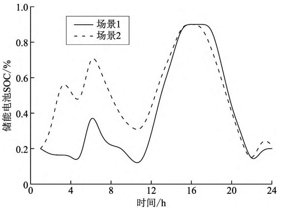
The optimized SOC curves for a typical day in the year of operation under two scenarios are shown in Figure 3, and the remaining capacity of the optimized battery is shown in Figure 4.
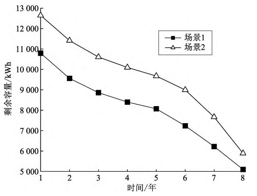
As shown in Figure 4, with the increase of operating years, the capacity of energy storage batteries decreases year by year, and the decay rate accelerates with the increase of operating years. At the end of operating years, the battery capacity has already decayed by over 50%. The attenuation law of battery capacity in both scenarios is roughly the same, and the remaining capacity in Scenario 2 is always higher than that in Scenario 1 during the same period of operation. This indicates that it is necessary to consider the impact of capacity attenuation on the configuration of energy storage power stations when optimizing.
5.3 Economic Benefit Analysis
Optimize the configuration of shared energy storage power plants in two scenarios using the methods mentioned above, and the optimization results are shown in Table 1. In scenario 3 where the CCHP system is not equipped with an energy storage system, the new energy consumption rate is 68.9%, and after configuring shared energy storage, the new energy can be fully consumed. Compared to Scenario 1, Scenario 2, and Scenario 3, after adding a shared energy storage plant, the operating costs of microgrid users in the CCHP system decreased by 11.87% and 13.17%, respectively. The configuration capacity of scenario 2 shared energy storage power station has increased by 17.16% compared to scenario 1, and the corresponding configuration investment has increased by 17.16%. Due to the larger configuration capacity in Scenario 2, the operating cost of the CCHP system has decreased significantly compared to Scenario 1. From this, it can be seen that the shared energy storage business model can help CCHP systems reduce wind and light waste, and reduce operating costs.
| Scene | Rated power of the power station/kW | Rated capacity/kWh | Present value of allocation investment/10000 yuan | Annual average operating cost of CCHP system/10000 yuan | Annual new energy consumption rate/% |
| 1 | 4050 | 10796 | 2453.10 | 2383.2 | 100 |
| 2 | 4745 | 12650 | 2874.10 | 2348.8 | 100 |
| 3 | —— | —— | —— | 2704.4 | 68.9 |
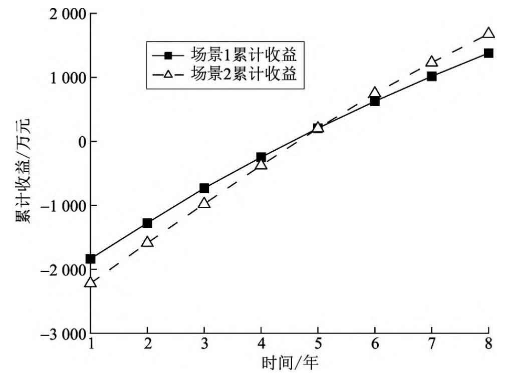
Analyze the profitability of shared energy storage power stations, taking the cumulative net profit of each year minus investment cost as the cumulative net income of shared energy storage power stations, and calculate the cumulative net income curves of two configuration schemes as shown in Figure 5. Comparing the cumulative net income curves of the two, in the early stage of system operation, Scenario 1 had a slightly higher cumulative net income than Scenario 2 due to low initial investment. However, as the operating years increased, the battery capacity continued to decrease, and Scenario 1 had a more significant decrease in cumulative net income. Scenario 2 considers the possible attenuation during the operating cycle during the initial configuration stage. Although the battery capacity attenuation pattern is similar to Scenario 1, due to the larger configuration capacity, the energy storage battery can maintain a larger remaining capacity at the end of operation. Therefore, the rate at which annual revenue decreases with increasing operating years is slower compared to Scenario 1. After 5 years of system operation, the cumulative net income of scenario 2 exceeds that of scenario 1. The net income of the two schemes changed from negative to positive at around 4.5 years, indicating that the shared energy storage power station has recovered its investment costs and turned into a profitable state. At the end of the operating period, the cumulative net income of scenario 2 system increased by 21.68% compared to scenario 1.
6 Conclusion
This article studies the configuration of shared energy storage. Based on the scenario of shared energy storage power station serving CCHP system, a dual layer optimization configuration model for shared energy storage considering battery loss is proposed. The model is transformed using KKT complementary relaxation conditions and solved using the CPLEX solver. Analyzed the SOC curve of energy storage batteries, calculated the annual charging and discharging times of batteries using the rain flow method, and obtained the changes in SOH of energy storage batteries during the operation of shared energy storage power stations. Through example analysis and comparison with conventional configuration methods that do not consider battery loss, the profitability of shared energy storage power stations within their lifecycle is analyzed, and the following conclusions are drawn:
a) The shared energy storage model can reduce the operating costs of multiple CCHP systems and improve the system’s new energy consumption rate while achieving self profitability.
b) During the operation period of shared energy storage stations, the capacity of energy storage batteries has significantly decreased, and changes in battery health status should be taken into account when configuring energy storage stations.
c) The configuration method proposed in this article can better consider the changes in battery health status during the operation period when configuring shared energy storage power plants, and has better adaptability in practical application scenarios.
d) After considering battery decay, shared energy storage power stations require greater upfront investment, but with stronger profitability in the later stages, they can basically achieve cost recovery and have more profit potential than without considering battery capacity decay.