
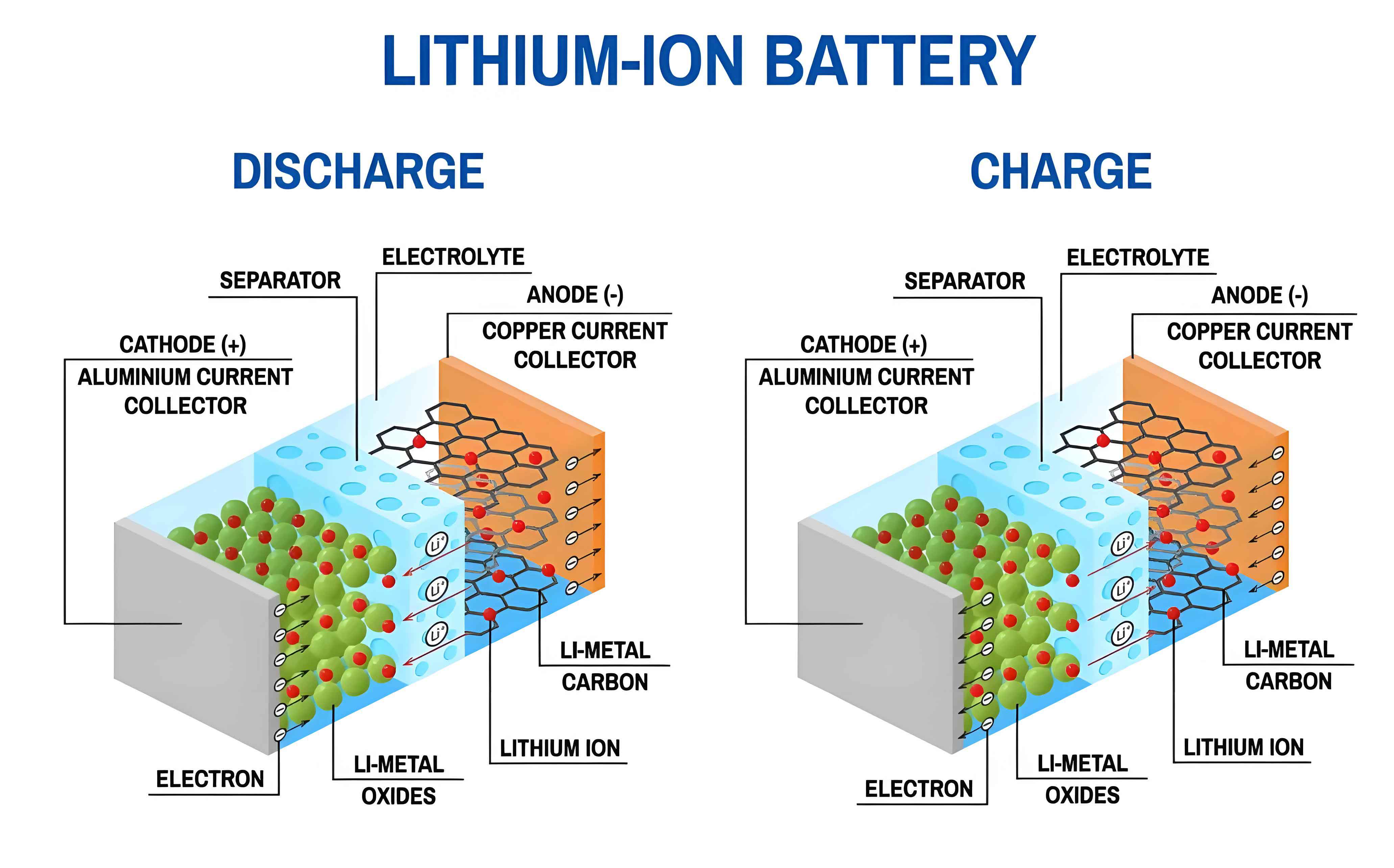
The widespread adoption of electric vehicles (EVs) is a critical strategy for addressing environmental concerns and mitigating energy crises. The lithium-ion battery, renowned for its high energy density, low self-discharge rate, long cycle life, and environmental friendliness, has become the dominant energy storage solution in modern EVs. However, its performance is severely hampered in cold climates. At low temperatures, the kinetic and transport properties of the lithium-ion battery materials degrade significantly, leading to a substantial drop in available capacity and power, increased internal resistance, and heightened risks of lithium plating during charging, which can accelerate aging and cause safety hazards.
Solutions to the low-temperature challenge primarily involve developing new electrochemistries or implementing external heating. While significant research is dedicated to creating wide-temperature-range electrolytes and electrodes, the development cycle is long, and a robust commercial solution remains elusive. Therefore, actively heating the lithium-ion battery from a low temperature to its optimal operating range is currently the most practical and widely researched approach. Heating methods are categorized based on the heat source: external and internal. External methods apply heat from outside the cell, often using fluids, air, or electric heaters. While simpler to implement, they typically suffer from low heating rates, poor temperature uniformity, and significant energy losses. Internal heating methods generate heat within the lithium-ion battery itself, offering faster and more uniform warming. Among these, AC (alternating current) heating has attracted considerable attention due to its high efficiency and relatively low impact on battery health compared to high-rate DC pulses.
Traditional AC heating often relies on an external AC power source, such as a grid-connected inverter or wireless charging system, to impose an alternating current on the lithium-ion battery. However, this dependency limits its application, particularly during cold starts where an external power source is unavailable. Recent advancements focus on “self-heating” topologies, where the lithium-ion battery itself, potentially in conjunction with other cells, provides the energy for the AC excitation through resonant circuits. Existing self-heating circuits often employ series-resonant structures or require pairing batteries into groups, leading to limitations such as uncontrollable current amplitude, complex control for maintaining consistency, or inapplicability to single-cell scenarios. To overcome these challenges, this work proposes a novel, simple, and versatile parallel-resonant AC self-heating circuit. This circuit enables controllable AC self-heating for both individual lithium-ion battery cells and series-connected modules, paving the way for more efficient and universally applicable battery thermal management in freezing conditions.
Circuit Topology and Operational Principles
The proposed self-heating circuit topology is designed for simplicity and controllability. It consists of four main components: the target lithium-ion battery (B), an inductor (L), a capacitor (C), and two semiconductor switches (Q1 and Q2). The inductor and capacitor are placed on two parallel branches, forming the core of the parallel-resonant structure. The lithium-ion battery acts as the energy source. The switches are controlled by a pair of complementary PWM (Pulse Width Modulation) signals, PWM1 and PWM2. By orchestrating the on/off states of these switches, energy is cyclically exchanged between the lithium-ion battery, the inductor, and the capacitor, thereby generating an alternating current through the battery for internal Joule heating.
The operational cycle of this circuit can be distinctly divided into four stages, as illustrated in the theoretical waveforms. The key to current control lies in the parameter \( t_{on} \), which is the total duration within one period when the battery is connected to the circuit (i.e., when Q1 is on).
Stage I (Battery Discharges to Inductor): At the beginning of a cycle (t=0), Q1 is turned ON and Q2 is OFF. The lithium-ion battery discharges into the inductor. The inductor current \( i_L \) rises linearly from zero, approximated by:
$$ i_L(t) = \frac{U_{bat}}{L} t, \quad 0 \leq t \leq t_1 $$
where \( U_{bat} \) is the terminal voltage of the battery (approximately its OCV during the short pulse), and \( L \) is the inductance. This stage ends at \( t_1 \), controlled by the PWM signal.
Stage II (Inductor Discharges to Capacitor): At \( t_1 \), Q1 turns OFF and Q2 turns ON. The inductor now discharges its stored energy into the capacitor. The inductor current and capacitor voltage engage in a resonant exchange. The current decays in a sinusoidal manner:
$$ i_L(t) = i_{L,max} \cos[\omega (t – t_1)], \quad t_1 \leq t \leq t_2 $$
where \( \omega = 1/\sqrt{LC} \) is the resonant angular frequency, and \( i_{L,max} \) is the peak current reached at \( t_1 \). This stage ends at \( t_2 = t_1 + T/4 \), when the inductor current reaches zero and the capacitor voltage is at its maximum.
Stage III (Capacitor Discharges to Inductor): With Q2 still ON, the capacitor begins to discharge back into the inductor, causing the inductor current to reverse direction.
$$ i_L(t) = 0, \quad \text{at } t=t_2 $$
The current becomes negative and reaches its negative peak at \( t_3 = t_1 + T/2 \).
Stage IV (Inductor Charges the Battery): At \( t_3 \), Q1 turns ON again and Q2 turns OFF. The inductor, now with negative current, discharges back into the lithium-ion battery, effectively returning a portion of the energy.
$$ i_L(t) = \frac{U_{bat}}{L} (t – t_3), \quad t_3 \leq t \leq t_4 $$
This stage ends at \( t_4 \) when the inductor current returns to zero, completing one full heating cycle. The next cycle then begins.
The fundamental frequency of the heating current \( f_{heat} \) and the duty cycle \( D_{heat} \) are defined by:
$$ f_{heat} = \frac{1}{t_{on} + t_{off}}, \quad D_{heat} = \frac{t_{on}}{t_{on} + t_{off}} $$
where \( t_{off} = t_3 – t_1 = T/2 \) is essentially half the resonant period. Crucially, the amplitude of the AC current is directly proportional to \( t_{on} \). Therefore, by modulating the PWM signal to control \( t_{on} \), the root-mean-square (RMS) heating current can be precisely regulated, which is a significant advantage over fixed-frequency resonant schemes.
Mathematical Modeling and Simulation
To support the analysis and development of control strategies, a circuit model incorporating internal resistances was established. The model includes the battery’s internal resistance \( R_{bat} \), the inductor’s DC resistance \( R_L \), the capacitor’s equivalent series resistance (ESR) \( R_C \), and the on-resistance of the MOSFETs \( R_{Q1}, R_{Q2} \). The battery’s open-circuit voltage (OCV) is represented by \( U_{OC} \). The governing equations for Stage I are derived from Kirchhoff’s voltage law (KVL):
$$ L \frac{di_L}{dt} = U_L $$
$$ U_{OC} – i_L R_{eq1} – i_L R_L – U_L = 0 $$
where \( R_{eq1} = R_{bat} + R_{Q1} \). Solving these with the initial condition \( i_L(0) = 0 \) gives:
$$ i_L(t) = \frac{U_{OC}}{R_L + R_{eq1}} \left[ 1 – \exp\left( -\frac{R_L + R_{eq1}}{L} t \right) \right] $$
For the short pulse durations used, this simplifies to the linear approximation shown earlier. Similar modeling applies to Stages II/III (resonant stage) and Stage IV. A simulation was conducted using parameters from a later experiment (L=10.9 µH, C=7.2 µF, \( t_{on}=28 \mu s \), \( U_{bat} \approx 3.7V \)). The simulated current waveform closely matched the experimentally measured one, with a peak current error of only 4.19%, validating the model’s accuracy for predicting current behavior and facilitating control strategy design.
Experimental Investigation and Parametric Analysis
A comprehensive test platform was established to validate the circuit’s performance. It consisted of a battery test system for characterization, an electrochemical impedance spectrometer (EIS), and the core heating test bench. The heating bench featured a DSP controller generating PWM signals, power MOSFETs, and the L-C resonant components, all placed inside a thermal chamber set to -25°C. Current was measured with a high-bandwidth current probe, and battery surface temperature was monitored using K-type thermocouples. Commercial 18650 lithium-ion battery cells with a nominal capacity of 2400 mAh were used.
Impact of Pulse Width (\( t_{on} \)): The pulse width \( t_{on} \) is the primary control knob for adjusting heating current. Tests were conducted with fixed L and C values (3.9 µH, 2.6 µF), varying \( t_{on} \) from 30 µs to 38 µs. The results are summarized below:
| Pulse Width \( t_{on} \) (µs) | Current RMS (C-rate) | Avg. Heating Rate (°C/min) | SOC Consumption per °C (γ) |
|---|---|---|---|
| 30.0 | 2.21 | 2.34 | 7.8e-3 |
| 31.7 | 2.34 | 2.65 | 7.4e-3 |
| 33.3 | 2.48 | 3.00 | 6.9e-3 |
| 35.0 | 2.62 | 3.43 | 6.3e-3 |
| 36.7 | 2.76 | 3.77 | 6.1e-3 |
| 38.0 | 3.00 | 4.30 | 6.6e-3 |
The data clearly shows that increasing \( t_{on} \) linearly increases the RMS current, which in turn significantly boosts the heating rate due to the square relationship between Joule heat and current \( (P_{heat} = I_{RMS}^2 R_{int}) \). The efficiency, characterized by the SOC consumed per degree of temperature rise (γ), generally improves until an optimum point (around 36.7 µs) before slightly decreasing at very high currents, likely due to increased overpotential losses.
Impact of Initial State of Charge (SOC): The battery’s OCV decreases with SOC, which affects the driving voltage for the heating current. Tests were performed at a fixed \( t_{on} \) of 36.7 µs across different initial SOC levels.
| Initial SOC (%) | Current RMS (C-rate) | Avg. Heating Rate (°C/min) | SOC Consumption per °C (γ) |
|---|---|---|---|
| 100 | 3.10 | 4.03 | 5.7e-3 |
| 75 | 2.88 | 3.57 | 6.2e-3 |
| 50 | 2.58 | 2.90 | 7.0e-3 |
| 25 | 2.52 | 3.85 | 4.7e-3 |
From 100% to 50% SOC, the decreasing OCV causes a reduction in heating current and rate. However, at 25% SOC, despite a similar current level to 50% SOC, the heating rate surges. This is attributed to the significant increase in the internal resistance of the lithium-ion battery at low SOC, leading to higher Joule heat generation for the same current. Consequently, the heating efficiency (lower γ) is best at the low SOC of 25% under these fixed parameters.
Impact of Heating Frequency and Series Connection: The heating frequency \( f_{heat} \) is determined by \( t_{on} \) and the resonant period T. Higher frequencies can be achieved by using smaller L and C values or by increasing the number of cells in series (\( N_{series} \)), which raises the circuit’s driving voltage \( U_{pack} = N_{series} \times U_{cell} \). Experiments were conducted to compare heating a single cell versus a 2-cell series module, maintaining a similar RMS current of 2.7C.
| Configuration | L (µH) | C (µF) | \( f_{heat} \) (kHz) | Avg. Heating Rate (°C/min) | γ |
|---|---|---|---|---|---|
| Single Cell | 10.9 | 7.2 | 12 | 3.11 | 7.0e-3 |
| 2-Cell Module | 3.9 | 2.6 | 31 | 4.57 | 4.4e-3 |
The module heated significantly faster and more efficiently. The higher frequency (31 kHz vs. 12 kHz) reduces the per-cycle energy exchanged, allowing for more heating cycles per second and potentially better matching with the lithium-ion battery‘s frequency-dependent impedance. Further tests on a 4-cell series module showed good temperature uniformity with a maximum difference of 2.5°C during heating, demonstrating the circuit’s scalability.
Proposed Heating Control Strategy and Circuit Enhancement
The experimental analysis revealed a key challenge: in the mid-to-high SOC range (50%-100%), the heating rate decreases as SOC drops because the current diminishes with the falling OCV. To maintain a consistent and safe heating performance, a closed-loop control strategy is essential. Based on the circuit model, the current amplitude is proportional to \( U_{OC} \cdot t_{on} \). Therefore, to keep the RMS current constant at a target value \( I_{target} \), the pulse width \( t_{on} \) should be adjusted inversely with the estimated OCV.
A linearized control law is derived from the battery’s OCV-SOC relationship. For the tested lithium-ion battery, the OCV between 50% and 100% SOC is approximately linear. A control strategy is formulated as:
$$ t_{on}(z) = a \cdot z + b $$
where \( z \) is the estimated SOC, and \( a \) and \( b \) are coefficients calibrated from the OCV curve and circuit parameters. For our cell, \( a = -0.0938 \mu s/\% \) and \( b = 44.11 \mu s \). Implementing this strategy experimentally successfully stabilized the RMS current around 2.8C and maintained a heating rate near 3.0 °C/min across the 50%-100% SOC range, validating the approach.
To address temperature inconsistency in larger modules, an enhanced, switchable circuit topology is proposed. The core idea is to retain the ability to heat the entire module for efficiency but also to selectively heat individual underperforming cells to improve uniformity. This is achieved by incorporating a set of switches (\( S_{k1}, S_{k2} \)) for each cell in the module. Under normal operation, all cells are connected in series for bulk heating. If a cell (e.g., B1) is detected to be colder than others, its bypass switches can be reconfigured to temporarily connect it to a dedicated heating circuit (a separate instance of the proposed topology) or to short it out while the remaining cells continue heating. This flexible architecture allows the Battery Management System (BMS) to balance heating speed with temperature homogeneity.
Comparative Analysis
The proposed method is compared against other prominent low-temperature heating techniques in the table below.
| Heating Method | Energy Source | Current Controllability | Key Advantage | Key Limitation |
|---|---|---|---|---|
| External PTC/Heater | Battery / Grid | Yes | Simple, Safe | Slow, High Gradient, Low Efficiency |
| DC Pulse (e.g., E-triggered) | Battery | Limited | Very Fast Heating, Simple Circuit | High Energy Waste in Load, Large Current Stress |
| External AC Heating | Grid / Wireless | Yes | High Efficiency, Low Battery Stress | Requires External Power Source |
| Series-Resonant Self-Heat. | Battery | No | Simple Circuit, Sinusoidal Current | Uncontrollable Current, Performance Varies with SOC |
| Paired-Battery Self-Heat. | Battery | Yes | Controllable, Efficient | Requires Paired Cells, Complex for Single Cell |
| Proposed Parallel-Resonant Self-Heat. | Battery | Yes | Controllable, Single/Multi-cell, Simple Topology | Current waveform is triangular, not sinusoidal |
The proposed circuit for lithium-ion battery heating occupies a unique position by offering controllable AC self-heating with a simple two-switch topology applicable to any number of series-connected cells. Its main drawback is the non-sinusoidal current waveform, which may have a slightly different impact on battery aging compared to a pure sine wave, a topic for future study.
Conclusion
This work presents a comprehensive study on a novel AC self-heating circuit for lithium-ion battery low-temperature applications. The parallel-resonant topology enables the generation of controllable alternating current directly from the battery’s own energy, eliminating the need for an external AC source or paired battery groups. A mathematical model of the circuit was developed and validated, showing excellent agreement with experimental current waveforms. Through extensive parametric testing, the influences of pulse width, initial SOC, heating frequency, and series cell count were quantified. Key findings include: 1) Heating rate is directly controllable via the PWM pulse width (\( t_{on} \)); 2) Higher heating frequencies, achievable with smaller L/C components or series-connected modules, lead to faster and more efficient warming; 3) A control strategy that adjusts \( t_{on} \) based on SOC (via OCV) can effectively stabilize the heating current and performance across a wide SOC range; 4) The circuit scales well to modules with good temperature uniformity, and a switchable enhanced topology is proposed for active consistency management.
The proposed method successfully demonstrated heating rates exceeding 3.1 °C/min for a single cell and 4.5 °C/min for a module, with the capability to operate from at least 25% to 100% SOC. Future work will focus on optimizing the L and C selection, thoroughly investigating the long-term aging effects of this specific current waveform on the lithium-ion battery, and developing advanced model-predictive control strategies that account for real-time temperature and resistance feedback.