
After completing the MPPT control optimization and topology optimization of the solar inverter, it is necessary to select and design the key components of the entire photovoltaic power generation system in order to ensure the optimal operation of the entire system. The selection of key devices in photovoltaic power generation systems directly determines the output efficiency and quality of the entire system, making it crucial for solar inverter experiments.
For T-type three-level solar inverters, in order to achieve balance of DC bus voltage and improve power supply quality, DC bus capacitors are widely used in the industry, which can absorb the ripple current at the rectifier end, control the harmonic voltage of the bus within a certain range, and make the output of the solar inverter more stable. The selection of DC bus capacitors should be comprehensively considered from various aspects such as voltage, capacitance value, and capacitor life. This article selects appropriate DC bus capacitor devices through the calculation of ripple current and capacitance value.
Ripple current generally refers to the AC current passing through the capacitor. When the ripple current exceeds the rated value, the internal heating caused by the ripple current will increase by 5 ℃, and the lifespan of the capacitor will be reduced by 50%. Therefore, controlling the ripple current is a guarantee for the long-term stable operation of solar inverters.
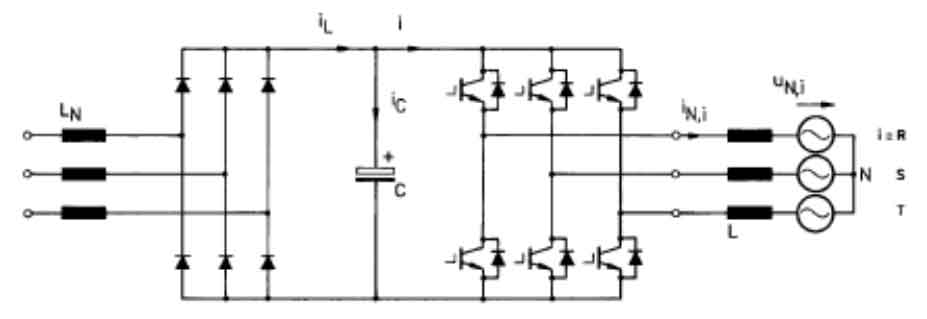
In practical engineering applications, the method for solving ripple currents also varies depending on the target audience. Based on whether the DC side is a constant power source and the different usage scenarios, common methods can be roughly divided into uncontrolled rectifiers and solar inverters. The topology of the rectifier is shown in Figure 1.
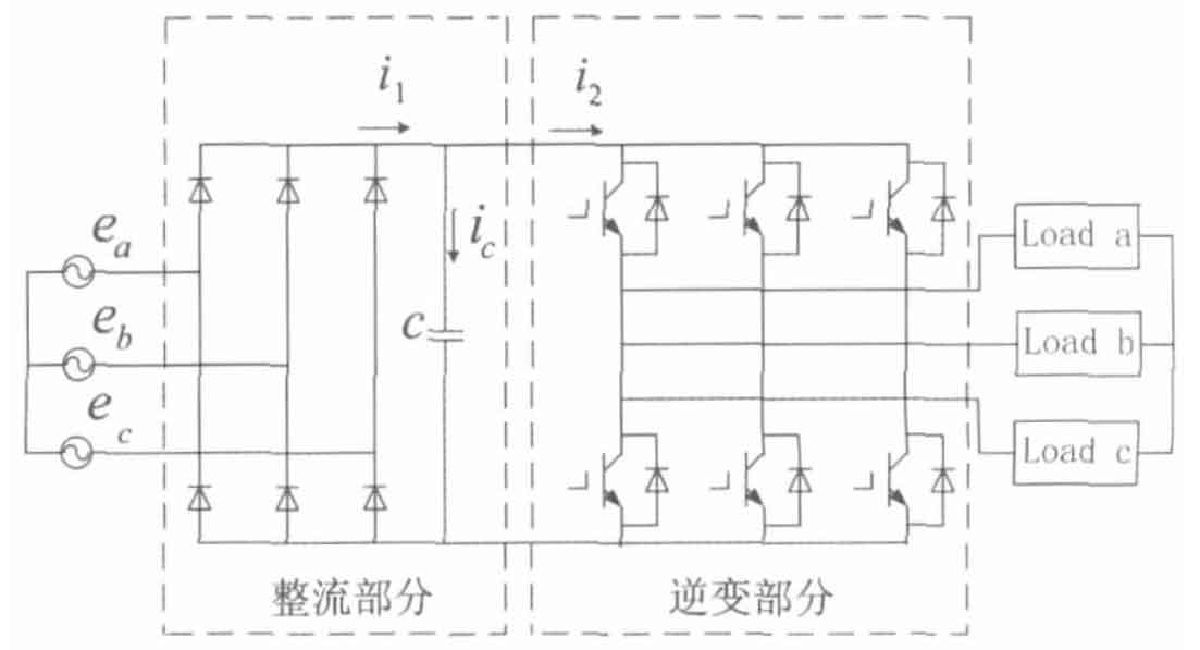
As shown in Figure 1.
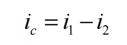
Among them, ic is the ripple current, i1 is the rectified output current, and i2 is the input current of the solar inverter. For the latter two currents, which also include the DC and AC parts, the formula can be rewritten as follows:
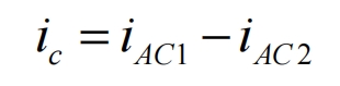
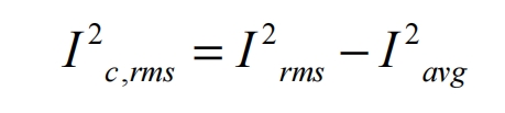
It is obvious that the ripple current of the DC bus capacitor is only composed of the AC component of the above two currents, and due to:
Substituting the formula into it yields:
In the formula, ϕ U=2 π fst; Fs is the rectification output frequency.
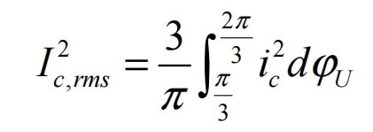
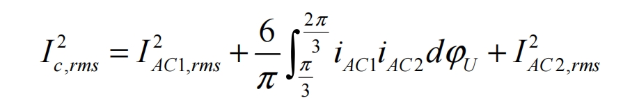
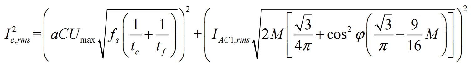
Due to the presence of harmonic components of different frequencies in the rectified output current and the input current of the solar inverter, according to the Passawal theorem, it can be obtained that:
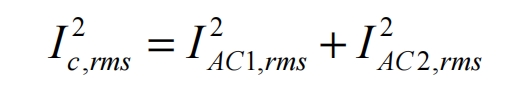
It can be clearly seen from the formula that the effective value of ripple current in the DC bus capacitor is composed of the AC component of the rectifier circuit and the AC component of the input current of the solar inverter. The AC component of the rectifier circuit can be calculated as follows:
If the voltage ripple rate of the DC bus is defined as a=Δ U/Umax, then:
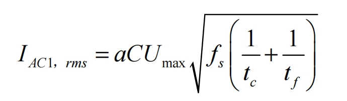
In the formula, Umax is the maximum value of the rectified output voltage, C is the DC bus capacitor, and tc and tf are the charging and discharging times of the bus capacitor, respectively.
The ripple current value on the input side of the solar inverter is:
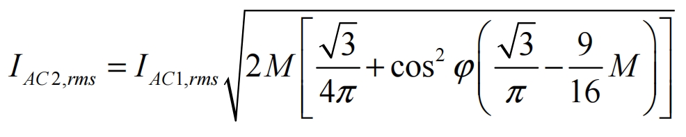
In the formula, M is the PWM modulation ratio.
The ripple current is:
It is not difficult to see from the formula that the ripple current is related to capacitance value, modulation ratio, power factor, DC bus voltage ripple, and is directly proportional to capacitance value. Therefore, blindly increasing the DC bus capacitance value will inevitably cause an increase in ripple current, which is not conducive to the long-term stable operation of the device.
Similarly, for the calculation of ripple current in solar inverters, since the DC side is the stable voltage output by the photovoltaic cell, there is no rectification part on the DC side. The common topology structure of passive solar inverters is shown in Figure 2.
For a symmetrical sinusoidal three-phase voltage/current system, the input current of the solar inverter is displayed as a constant DC value. Therefore, the average DC input current iavg is equal to the average output current Iavg of the solar inverter, which is:
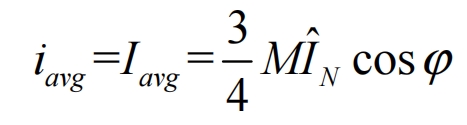
In the formula, M is the modulation ratio; ˆ NI is the peak value of the rated output current of the solar inverter; ϕ Is the phase shift angle.
It is not difficult to see that the average DC input current is related to the phase shift angle. When cos=0 ϕ When, it is considered as all reactive power, and the harmonic component at this time is 0; When cos=1 ϕ At this time, it is considered as pure active power, and the harmonic component has a maximum value. At the same time, the DC input current is also related to the modulation ratio. According to the actual situation of the experimental platform, the corresponding voltage value for the maximum power occurrence is 700V. At this time, the modulation ratio is 0.734, so theoretically, the maximum DC input current value is at this time. But the above conclusions are based on only considering the harmonic effects of switching frequency, without considering the effects of low-frequency harmonics. In practical engineering applications, the influence of low-frequency harmonics is often reduced through software control, setting up low-frequency filtering devices, etc. Therefore, ignoring the influence of low-frequency harmonics is feasible.
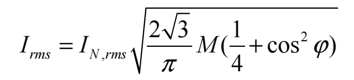
The effective value Irms of the input current of solar inverters is also an important parameter for ripple current calculation, and its calculation method is as follows:
According to the previous text, the ripple current is:
Substitute the formula into the final expression of the ripple current:
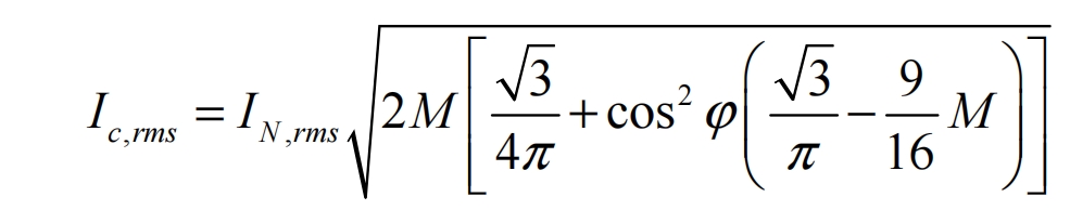
By using a formula, the ripple current of a constant voltage source solar inverter can be calculated. It is not difficult to see that in this usage scenario, the ripple current is related to the rated output current, modulation ratio, and phase shift angle of the solar inverter.
Ripple current is an important criterion for selecting DC bus capacitor devices, but it is not the only one. The magnitude of its capacitance directly affects the charging and discharging energy of the capacitor in the on and off states of the power switch tube. Therefore, the selection of capacitance value is also crucial for the stable operation of the entire solar inverter system.
During a complete PWM cycle, when the power switch is turned on, both the bus capacitor and the photovoltaic cell provide electricity to the solar inverter; When the power switch is turned off, the photovoltaic cell charges the bus capacitor and stores energy. Therefore, within one switching cycle, the energy required for the busbar is:
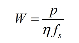
In the formula, P is the maximum DC input power; η The conversion efficiency of solar inverters; Fs is the switching frequency.
Within one switching cycle, the energy provided by the capacitor is:
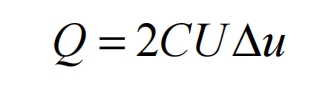
In the formula, U is the DC bus voltage, generally taking the minimum DC voltage within the MPPT voltage range; Δ U is the ripple voltage of the DC bus, as mentioned earlier, Δ U=aUmax.
Since the charging and discharging of the bus capacitor are completed within half a cycle, it is considered that the energy provided by the capacitor in one cycle is half of the energy required by the bus. Based on the formula, the DC bus capacitor value can be obtained as:
In practical engineering applications, the selection of DC bus capacitors is often based on these two parameters, and of course, parameters such as temperature, voltage level, and service life are also used as selection criteria.
| Name | Maximum input power (kW) | Maximum input voltage (V) | Minimum operating voltage (V) | MPPT voltage range (V) | Rated output power (kW) | Rated output voltage (V) | Inverter efficiency (%) |
| Parameters | 560 | 1000 | 450 | 450-820 | 500 | 315± 10% | 98.7 |
Based on the detailed parameters of the experimental platform and the theoretical calculations mentioned above, the selection and design of DC bus capacitors have been made. The required parameters for the design are shown in the table.
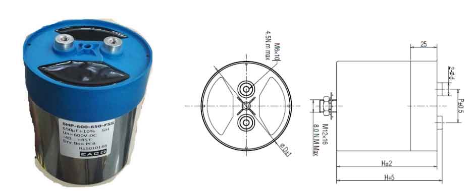
According to the previous theoretical calculation, the ripple current is 120A and the capacitance value is 788uf. In order to provide a certain margin for the system, a margin coefficient of 1.5 is taken, resulting in a ripple current of 180A and a capacitance value of 1182uf. For these two parameter values, a DC link metal thin film capacitor was selected, with a single capacitance value of 650uf and a ripple current of 63A at 60 ℃. Considering better heat dissipation, 8 capacitors were used, and a connection method of four capacitors in parallel and then two sets in series was adopted. The equivalent capacitance is 1300uF, and the ripple current is 252A, all of which meet the DC bus capacitance parameter requirements with margin. The busbar capacitance is shown in Figure 3.