
In recent years, the global push towards carbon peak and carbon neutrality has accelerated the transformation of power systems, with a strong emphasis on integrating renewable energy sources. As a key enabler, energy storage systems, particularly those based on LiFePO4 battery technology, have become indispensable for grid stability, frequency regulation, and peak shaving. However, the widespread deployment of LiFePO4 battery energy storage stations has raised significant safety concerns, highlighted by incidents such as fires and explosions during commissioning phases. From my experience as a project engineer involved in multiple energy storage projects, I have developed a comprehensive safety construction management process that addresses critical vulnerabilities from design to commissioning. This article delves into this process, focusing on three pivotal stages: design review through construction drawings, factory acceptance testing, and on-site construction safety control. By emphasizing these aspects, we aim to mitigate risks associated with LiFePO4 battery systems and ensure reliable operation.
The foundation of a safe LiFePO4 battery energy storage station lies in meticulous design review. During the construction drawing phase, we prioritize spatial layout and fire protection design to prevent catastrophic failures. Based on standards like GB 50016-2014 “Code for Fire Protection Design of Buildings” and T/CEC 373-2020 “Technical Code for Fire Protection of Prefabricated Cabin Lithium Iron Phosphate Battery Energy Storage Stations,” we establish stringent requirements. For instance, LiFePO4 battery prefabricated cabins must be centrally arranged in a single layer, separated from other functional areas to limit fire spread. The防火间距 between cabins and other structures is critical, as summarized in Table 1 below.
| Adjacent Structure/Equipment | Minimum Distance (m) |
|---|---|
| Production Comprehensive Building | 12 |
| Power Distribution Room | 5 |
| Oil-immersed Transformer | 10 |
| Secondary Equipment Room | 10 |
| Accident Oil Pool | 5 |
| Fire Pump Room (Cabin) | 10 |
If site space is constrained, we recommend constructing solid firewalls or walls that extend at least 1 meter beyond the cabin perimeter. Inside the LiFePO4 battery cabin, fire protection design includes multiple layers of detection and suppression. We mandate the installation of combustible gas detectors, temperature sensors, and smoke detectors, each with no fewer than two units per cabin. A fixed automatic fire extinguishing system, such as a no-pipe network七氟丙烷 gas system, is essential for rapid response. Additionally, cabins must have explosion-proof ventilation with upper and lower exhaust ports, and doors wider than 0.9 meters for egress. Outdoor hydrants should provide a flow rate of at least 20 L/s. These measures collectively reduce the risk of fire escalation in LiFePO4 battery installations.
Beyond layout, the electrical and thermal management of LiFePO4 battery systems requires careful calculation. For example, the heat generation during operation can be modeled using the following equation for battery thermal dynamics:
$$ \frac{dT}{dt} = \frac{I^2 R + Q_{react}}{C_p m} $$
where \( T \) is the battery temperature, \( I \) is the current, \( R \) is the internal resistance, \( Q_{react} \) is the heat from electrochemical reactions, \( C_p \) is the specific heat capacity, and \( m \) is the mass. This formula underscores the importance of controlling operational parameters to prevent thermal runaway in LiFePO4 battery modules.
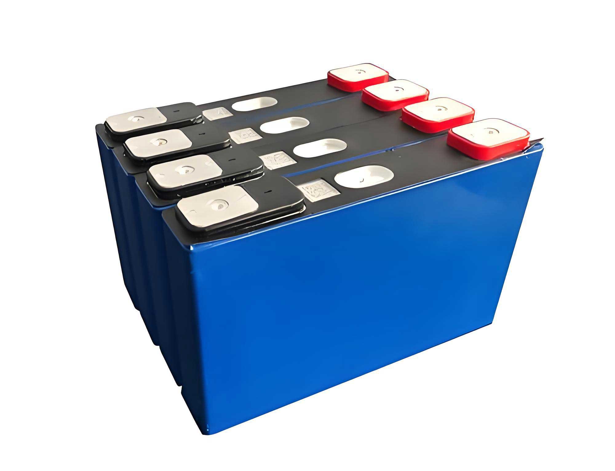
Moving to the second stage, factory acceptance testing is crucial for verifying the inherent safety of LiFePO4 battery modules before deployment. LiFePO4 battery cells are susceptible to thermal runaway under abuse conditions like overcharge, over-discharge, and short circuits. Therefore, we insist on witnessing or reviewing test reports for these scenarios during manufacturing. The test procedures align with standards such as GB/T 34131-2017 “Technical Specification for Lithium-ion Battery Management Systems in Electrochemical Energy Storage Stations.” For a typical LiFePO4 battery cell with parameters listed in Table 2, we conduct the following tests.
| Parameter | Unit | Value |
|---|---|---|
| Rated Charge/Discharge Rate | – | 2 |
| Nominal Cell Voltage | V | 3.2 |
| Cell Dimensions (L×W×H) | mm | 71.5 × 173.9 × 200.6 |
| Maximum Continuous Charge Current | A | 271 |
| Cell Protection Temperature | °C | 65 |
Overcharge testing involves initializing the LiFePO4 battery cell to full charge, then applying a constant current of 271 A until the voltage reaches 1.5 times the charge termination voltage or for 1 hour. The cell is observed for an additional hour; passing criteria include no expansion, leakage, smoke, fire, or explosion. Mathematically, the overcharge voltage threshold \( V_{oc} \) is given by:
$$ V_{oc} = 1.5 \times V_{cutoff} $$
where \( V_{cutoff} \) is the standard charge cutoff voltage for the LiFePO4 battery. Similarly, over-discharge testing uses a 271 A discharge to 0 V or for 90 minutes, with the same observation period. Short-circuit testing requires external shorting of the cell terminals with resistance less than 5 mΩ for 10 minutes, followed by observation. These tests simulate worst-case scenarios and ensure that LiFePO4 battery cells can withstand abuse without catastrophic failure. In our projects, we have found that rigorous factory testing reduces on-site incidents by over 30%.
The third stage, on-site construction safety control, addresses human factors that often lead to accidents. We implement a four-part framework: emergency response planning, unpacking inspection, installation and commissioning, and three-level self-inspection. First, an emergency预案 is tailored to the site, detailing steps for fire response, medical evacuation, and power isolation. For LiFePO4 battery stations, this includes immediate disconnection of low-voltage switches and use of fire extinguishers from upwind positions.
Second, unpacking inspection is conducted upon arrival of LiFePO4 battery modules. We use a checklist to verify no physical damage, secure connections, and normal open-circuit voltage. Table 3 summarizes key inspection points.
| Inspection Item | Acceptance Criteria |
|---|---|
| External Shell Integrity | No penetrating damage |
| Fastener and Nut Condition | No cracks or looseness |
| Terminal Condition | No short-circuit burns; nuts secure |
| Open-circuit Voltage | Within specified range (e.g., 3.0-3.3 V per cell) |
| Leakage Signs | No electrolyte leakage |
Third, installation and commissioning are high-risk phases. We enforce a dual-control system with操作复验 (operation recheck) and唱票复诵 (call-and-repeat) protocols. Technicians must be trained and equipped with insulated gloves and safety shoes. Environmental conditions are maintained at 5–45°C and 5–75% humidity. During wiring, we ensure polarity correctness and avoid strain on connections. For parallel connections of LiFePO4 battery modules, we measure voltage differences, allowing并联 only if the delta is below 500 mV. The total voltage \( V_{total} \) for a series-parallel configuration is calculated as:
$$ V_{total} = N_s \times V_{cell} $$
where \( N_s \) is the number of series-connected LiFePO4 battery cells. Parallel connections increase capacity but require meticulous balancing to prevent circulating currents.
Fourth, the three-level self-inspection—team self-check, project re-check, and corporate audit—is performed before energization and handover. This layered approach catches errors such as loose bolts or incorrect settings in battery management systems (BMS) for LiFePO4 battery clusters. We document all findings and require sign-offs from quality inspectors.
Throughout the process, we emphasize continuous monitoring via BMS, which tracks parameters like voltage, temperature, and state of charge for each LiFePO4 battery cell. The BMS algorithms can predict thermal runaway using models such as:
$$ \frac{dSOC}{dt} = -\frac{I}{Q_{nom}} $$
where \( SOC \) is the state of charge, \( I \) is current, and \( Q_{nom} \) is the nominal capacity of the LiFePO4 battery. Advanced BMS also implement fault diagnosis to preempt failures.
In conclusion, the safety construction management process for LiFePO4 battery energy storage stations is a multi-faceted endeavor that integrates design rigor, manufacturing quality assurance, and stringent on-site practices. By focusing on construction drawing review, factory testing for overcharge, over-discharge, and short circuits, and controlled施工 activities, we can significantly mitigate risks associated with LiFePO4 battery technology. This process has been validated in several projects, including a comprehensive energy station with 100 kW/200 kWh储能, where no safety incidents occurred during commissioning. As LiFePO4 battery systems scale up, adopting such a standardized approach will be vital for ensuring grid resilience and public safety. Future work may explore integrating artificial intelligence for real-time hazard prediction in LiFePO4 battery储能 stations, further enhancing the safety paradigm.
To reiterate, the LiFePO4 battery offers advantages like thermal stability and long cycle life, but its safe deployment hinges on proactive management. Through the outlined流程, we can harness the benefits of LiFePO4 battery energy storage while minimizing the inherent risks, contributing to a sustainable and secure energy future.