
This paper proposes a hierarchical coordinated control method for the resonance generated by grid connection of solar inverter clusters. The first layer proposes an active damping method based on forward channel series notch filter for capacitor voltage inertial feedback to suppress the internal resonance of the LCL solar inverter cluster, targeting the inherent resonance of the LCL solar inverter; In the second layer, a resonance suppression method based on PCC point parallel virtual admittance is designed to address the resonance generated by the impedance coupling between the solar inverter cluster and the power grid. The two-layer method works together to suppress cluster grid resonance and coordinate the optimization of grid connected current quality.
1. Inertial feedback method of capacitor voltage based on forward channel series notch filter
A capacitor voltage inertia feedback active damping method based on forward channel series notch filter is proposed for internal inherent resonance, and the control block diagram is shown in Figure 1. I1 is the reference value for system grid connected current, and ig1 is the grid connected current; Gi (s) is the current controller; GQ (s) is the capacitance voltage inertial feedback loop, where GQ (s)=- A/(Ts+1), where A and T are the proportional coefficients and time constants of the inertial loop, respectively. Because the filtering capacitor voltage of the three-phase LCL solar grid connected inverter control system must be sampled, the proposed control method can share a voltage sensor with the filtering capacitor voltage sampling stage. Compared with the traditional capacitor current proportional feedback control strategy, it saves a current sensor, reduces system costs, and adds a notch filter to optimize damping effect, fully suppressing the inherent resonance of the solar inverter.
According to Figure 1, the open-loop transfer function of the system is:
In the formula, ξ The damping coefficient is taken as 0 707; Gtrap (s) is the notch filter transfer function, expressed as:
In the formula, ω N is the center angular frequency; Q is the quality factor, which mainly affects the depth and width of the notch filter compensation. Figure 2 shows the Bode plot of Gtrap (s) when Q takes different values.
As shown in Figure 2, the signal is ω There is significant attenuation at n points, while the amplitude frequency characteristics of the other frequency bands are not affected, and the signal can pass through without attenuation. The smaller the Q value, the stronger the ability to suppress the inherent resonance point of the solar inverter, but the weaker the adaptability to grid frequency fluctuations, and vice versa; Therefore, a comprehensive Q value of 0 is selected 1. take ω Set n to the resonant frequency f1 of the LCL filter to improve the resonance suppression effect of the capacitor voltage inertia feedback control strategy.
Based on the system parameters and combined with the formula, draw the amplitude frequency characteristic curve of the capacitor voltage inertia feedback control strategy based on the forward channel series notch filter, as shown in Figure 3. After adopting the traditional capacitive current proportional feedback control strategy, the current resonance peak decreased from 114dB to -5 3dB can suppress resonance to a certain extent, but the system amplitude margin is relatively low. By using a notch filter based on forward channel to optimize the capacitance voltage inertia feedback control strategy, the peak value of the resonance point is reduced to -8 26dB, while the system achieves high amplitude and phase margin.
2. PCC point parallel virtual admittance method
The interaction coupling between solar inverter cluster system and grid impedance can easily cause global resonance, leading to system instability. The design of PCC point parallel virtual admittance YL (s) method is shown in Figure 4, which presents a high impedance state when encountering fundamental current, and can discharge high-frequency harmonic current to improve the quality of grid connected current. Therefore, a first-order high pass filter with a lower cutoff frequency can be used to extract higher-order harmonics in the grid connected current, except for the fundamental current. The damping at high frequencies can be increased to reduce the impact on the current near the fundamental frequency. The transfer function expression is:
In the formula, K is the time constant; Due to the cutoff frequency of the high pass filter fc=1/2 π K, K is taken as 0 At 003, the cut-off frequency was calculated to be 53Hz.
For the convenience of theoretical analysis, YL (s) is moved to the side of each solar inverter, and the virtual admittance is achieved in parallel with the PCC point by controlling the grid connected current of a single solar inverter. Each solar inverter is equivalent to adding a parallel feedback branch HGh (s), as shown in Figure 5. Gh is the first-order high pass filter, and H is the virtual admittance adjustment coefficient.
According to Figure 1 and Figure 5, combined with equation (9) analysis, the expressions for the output impedances Zout1 (s) and Zout2 (s) of the solar inverter before and after parallel virtual admittance are:
Analyze the relationship between the virtual admittance adjustment coefficient H and the output impedance of the solar inverter, when H is set to 0 (non parallel virtual admittance), 0 45, 0 55, 0 65, 0 The output impedance Bode diagram of the solar inverter at 75 is shown in Figure 6. As the value of H increases, the distance between the intersection point of the grid impedance Zg and the output impedance of the solar inverter is -90 °, indicating that the larger the value of H, the greater the phase angle margin of the output impedance of the solar inverter, and the higher the system stability margin. At the same time, there is no difference in the amplitude gain of the output impedance at the fundamental frequency compared to before adding virtual admittance, so the impact on the steady-state error of the grid connected current is relatively small. However, as the value of H increases, the amplitude of the output impedance in the low frequency range decreases, so H is comprehensively selected as 0 55.
3. System stability analysis
According to the impedance stability criterion, prove the resonance suppression ability of the proposed control strategy in the solar inverter cluster. If the ratio of the grid impedance to the output impedance of the solar inverter W=Zg/Zout meets the Nyquist stability criterion, the system reaches a stable state, where Zg=NZg represents the equivalent total grid side impedance value of N parallel solar inverters. According to the analysis, plot the Nyquist curves of PCC points before and after parallel virtual admittance, as shown in Figure 7, with the grid impedance taken as Lg=1mH.
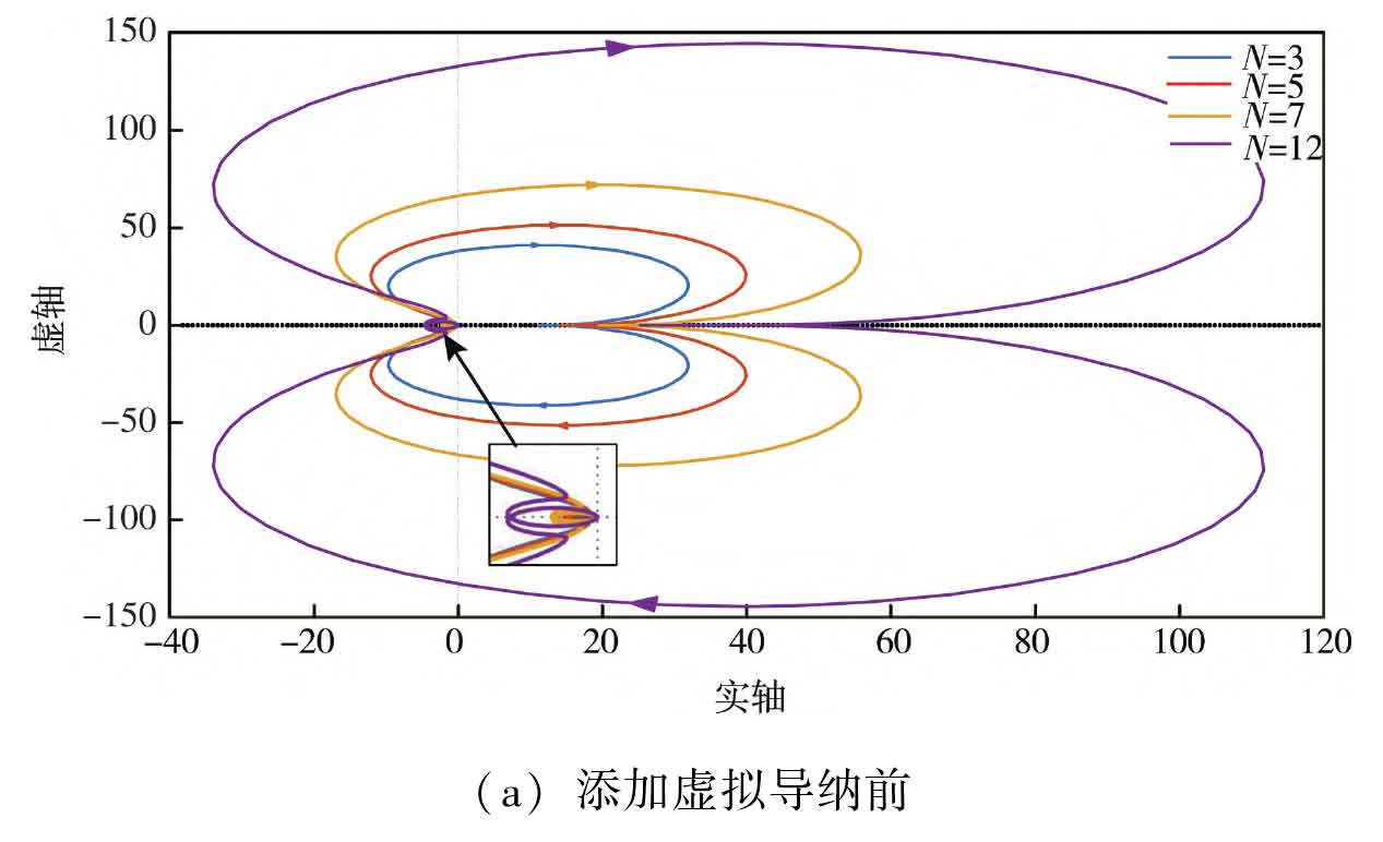
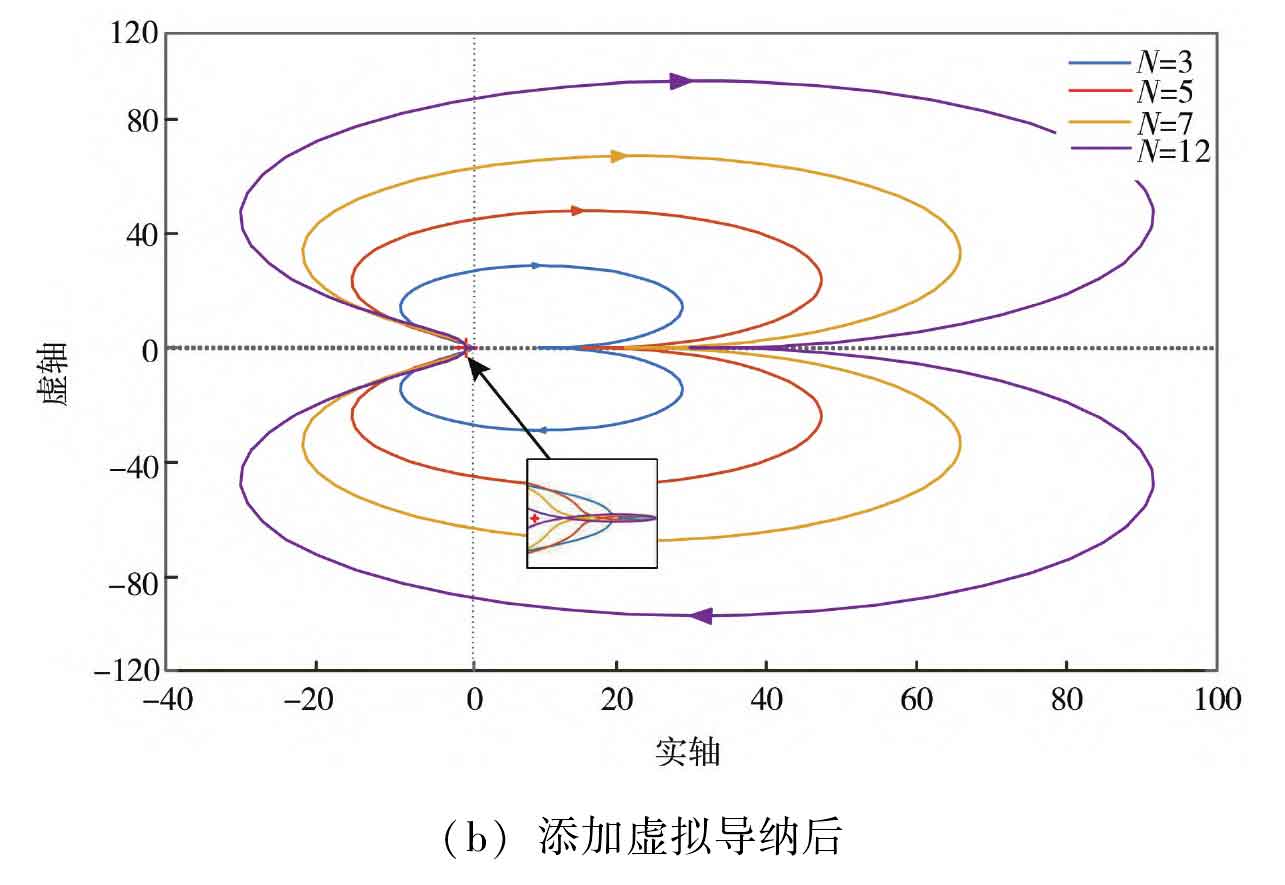
From Figure 7 (a), it can be seen that before using PCC point parallel virtual admittance, as the number of solar inverters in parallel increases, the ratio curve of grid impedance to solar inverter output impedance surrounds point (-1, j0), which does not meet the Nyquist stability criterion. At this point, resonance occurs in the solar inverter cluster grid connected system. From Figure 7 (b), it can be seen that after the virtual admittance of PCC points is connected in parallel, as the number of solar inverters connected in parallel increases, the impedance ratio curve can still meet the Nyquist stability criterion, and the system stability is strong, indicating that the proposed strategy has good suppression ability for the resonance caused by impedance coupling between the solar inverter cluster and the power grid.