
In this paper, I investigate the twin trawling test methodology for H-bridge power modules, a critical component in DC distribution and utilization systems. The integration of a battery energy storage system (BESS) as the DC source enables efficient power cycling and validation of module performance under full load conditions. This study aims to develop a comprehensive test platform that ensures reliability, safety, and accuracy for H-bridge modules used in applications like renewable energy integration, electric vehicle charging, and data centers. By leveraging a battery energy storage system, the test setup mimics real-world operational scenarios, allowing for rigorous evaluation of active and reactive power capabilities. The focus is on topology design, protection coordination, control strategies, and experimental procedures, all centered around the use of a battery energy storage system to facilitate energy exchange between modules.
DC distribution systems offer advantages over AC systems, including higher efficiency, reduced conversion losses, and enhanced controllability. H-bridge chain converters are pivotal in such systems due to their modularity and scalability. However, testing these modules at rated power requires sophisticated methods like twin trawling, where two modules operate in a back-to-back configuration. Here, I propose using a battery energy storage system for each module’s DC side, providing a stable and flexible energy reservoir. This approach not only simplifies test logistics but also aligns with the growing adoption of battery energy storage systems in grid applications. The twin trawling test validates module performance across various operating points, ensuring they meet stringent standards for power quality and reliability.
Topology Design of Main and Control Circuits
The main circuit topology for the twin trawling test is designed to facilitate bidirectional power flow between two H-bridge power modules. Each module is connected to an independent battery energy storage system on its DC side, forming a closed-loop energy exchange system. The circuit comprises an open-loop power module, a closed-loop power module, coupling inductors, and the battery energy storage systems. The open-loop module acts as a controlled voltage source, while the closed-loop module functions as a grid-tied inverter with active and reactive power control. This configuration allows for full-power testing without relying on external grids, leveraging the energy buffering capability of the battery energy storage system.
The H-bridge power module consists of four IGBTs arranged in a bridge configuration, with anti-parallel diodes for freewheeling. The output voltage of each module can be expressed as:
$$ V_{out} = m \cdot V_{dc} $$
where \( m \) is the modulation index (ranging from -1 to 1) and \( V_{dc} \) is the DC-link voltage supplied by the battery energy storage system. For a single-phase H-bridge, the output voltage waveform is generated using unipolar double-frequency modulation, which reduces harmonic distortion and switching losses. The switching frequency is set to 10 kHz, and the modulation scheme ensures that the output voltage pulse frequency is twice the switching frequency, improving waveform quality. The coupling inductor between modules limits current ripple and facilitates power transfer. Its value is critical for stability and is calculated based on the desired current ripple and power rating.
To summarize the main circuit parameters, I present Table 1, which outlines key components and specifications. The battery energy storage system parameters are based on lithium-ion technology, chosen for its high energy density and rapid response.
| Component | Parameter | Value |
|---|---|---|
| Battery Energy Storage System (BESS) 1 | Voltage Range | 600–800 V DC |
| Battery Energy Storage System (BESS) 2 | Capacity | 50 kWh |
| H-Bridge Power Module | Rated Power | 100 kVA |
| Coupling Inductor | Inductance | 5 mH |
| DC-Link Capacitor | Capacitance | 2000 µF |
| Switching Frequency | Frequency | 10 kHz |
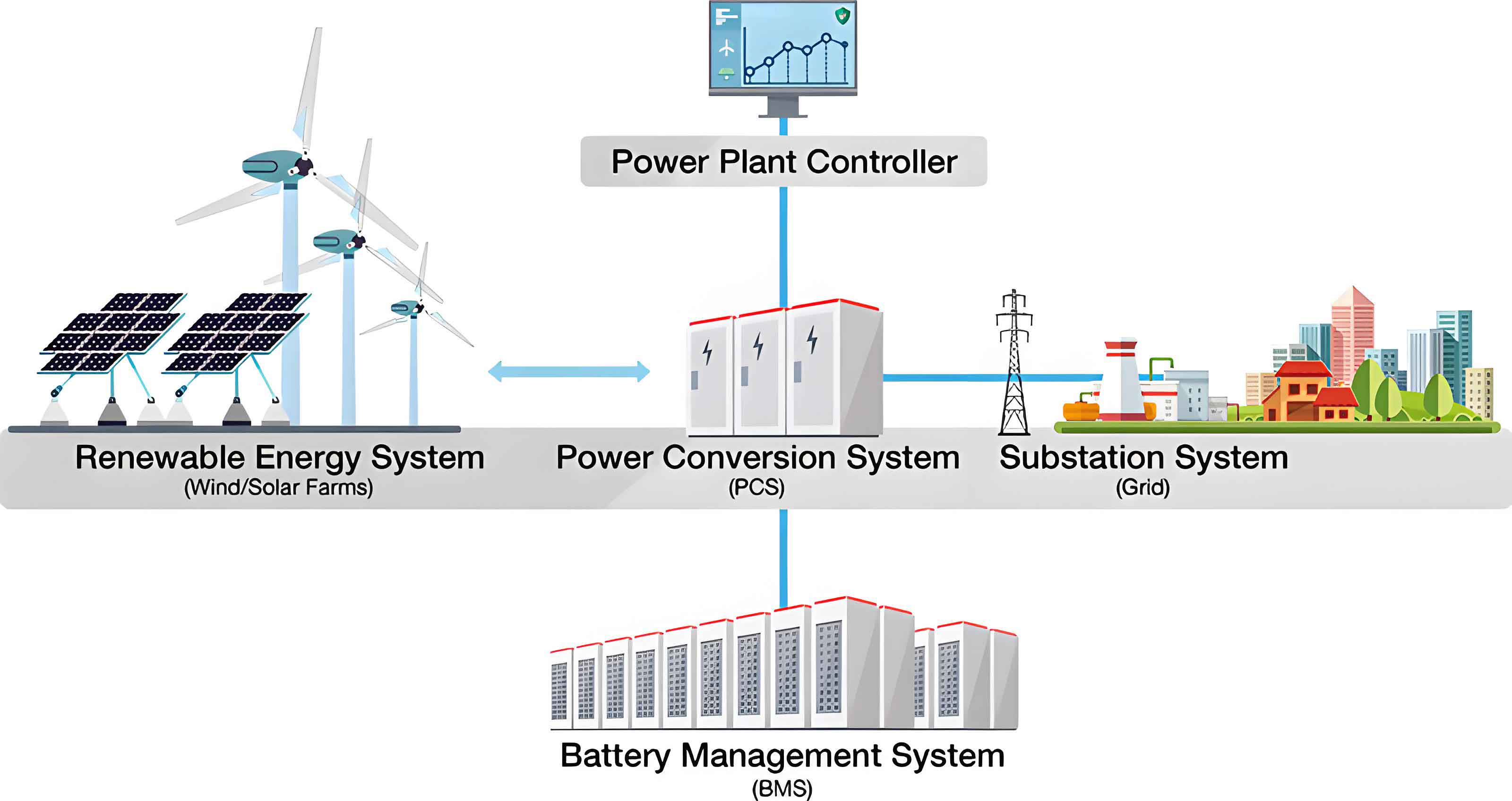
The control circuit topology is centered around a main controller that coordinates all subsystems via fiber-optic communication for isolation and safety. The main controller interfaces with the local controllers of each power module, the battery management system (BMS) of the battery energy storage system, and the water cooling system. Communication protocols include custom Manchester-encoded frames for module control and CAN bus for BMS data exchange. The local controllers manage real-time protection and switching, while the BMS monitors cell voltages, temperatures, and state of charge (SOC) of the battery energy storage system. This hierarchical control ensures precise operation and fault management.
The control loop for the closed-loop module implements a dq-axis current control strategy. The inductor current is transformed into synchronous reference frame components:
$$ i_d = \frac{2}{3} \left( i_a \cos(\theta) + i_b \cos(\theta – 120^\circ) + i_c \cos(\theta + 120^\circ) \right) $$
$$ i_q = -\frac{2}{3} \left( i_a \sin(\theta) + i_b \sin(\theta – 120^\circ) + i_c \sin(\theta + 120^\circ) \right) $$
where \( i_d \) and \( i_q \) are the active and reactive current components, and \( \theta \) is the phase angle from a phase-locked loop (PLL). The control objectives are set via the main controller’s touchscreen, allowing adjustment of target active current \( i_d^* \), target reactive current \( i_q^* \), and modulation index for the open-loop module. Proportional-integral (PI) regulators are used to track these references, with outputs converted to modulation waves via space vector modulation (SVM).
The integration of a battery energy storage system in this topology provides several benefits: it decouples the test from grid availability, enables energy recovery during regenerative braking, and allows for sustained full-power testing. The battery energy storage system’s response time and power capability are crucial for dynamic tests, and I have selected parameters to match the module ratings. Additionally, the use of a battery energy storage system facilitates testing under varying SOC conditions, simulating real-world degradation scenarios.
Protection Coordination and Action Principles
Protection coordination is essential to safeguard the test system, which includes the H-bridge modules, battery energy storage system, and auxiliary components. I have designed a multi-level protection scheme where the main controller oversees overall coordination, while subsystems handle local protections. The goal is to prevent damage from overcurrent, overvoltage, overheating, and communication failures, with the battery energy storage system playing a key role in isolating faults.
The local controller of each power module implements fast-acting protection based on hardware measurements. Protection events are categorized into alarms and lockouts. Alarms trigger warnings sent to the main controller, while lockouts immediately disable the IGBTs. For instance, DC-link overvoltage protection uses two thresholds: a warning at 850 V and a lockout at 900 V. The lockout condition is expressed as:
$$ V_{dc} > V_{dc,max} \rightarrow \text{Lockout} $$
where \( V_{dc,max} \) is the maximum allowable voltage. Similarly, temperature protection uses thermistors on IGBT heatsinks, with lockout triggered above 85°C. Other protection features include sync signal loss, pulse width anomalies, and ADC faults. All lockouts require a manual reset from the main controller after fault clearance, ensuring safe re-engagement.
The water cooling system protection is integrated via both digital I/O and RS485 communication. Critical faults, such as low flow rate or high coolant temperature, cause immediate lockout of the power modules. I summarize the water cooling protection events in Table 2, highlighting the coordination with the battery energy storage system. For example, a coolant leak detection triggers shutdown of the battery energy storage system relays to prevent energy inflow.
| Protection Type | Trigger Condition | Action |
|---|---|---|
| Flow Rate Low | Flow < 10 L/min | Lockout modules, open BESS relays |
| Coolant Temperature High | Temperature > 40°C | Alarm, reduce power |
| Pressure Low | Pressure < 2 bar | Lockout modules |
| Communication Fault | RS485 timeout | Lockout modules |
The battery energy storage system protection is managed by its BMS, which monitors cell-level parameters. The BMS communicates with the main controller via CAN bus, providing real-time data on voltage, temperature, and SOC. Protection actions include disconnecting relays for severe faults like overvoltage or overtemperature. The BMS also enforces soft limits via maximum allowable charge/discharge currents and powers, which the main controller uses to constrain operation. For example, the available discharge power \( P_{dis,max} \) from the battery energy storage system is computed as:
$$ P_{dis,max} = \min( V_{pack} \cdot I_{cell,max}, P_{thermal} ) $$
where \( V_{pack} \) is the total pack voltage, \( I_{cell,max} \) is the maximum cell current, and \( P_{thermal} \) is the thermal limit. The main controller ensures that the test power does not exceed these limits, preventing battery degradation. Key BMS protection events are listed in Table 3, emphasizing the integration with the overall system.
| BMS Protection | Threshold | System Action |
|---|---|---|
| Cell Overvoltage | > 4.2 V | Open relays, lockout modules |
| Cell Undervoltage | < 3.0 V | Open relays, lockout modules |
| High Temperature | > 45°C | Reduce power, alarm |
| Insulation Fault | Resistance < 500 Ω/V | Open relays, lockout |
| Communication Loss | CAN timeout > 1 s | Lockout modules |
The main controller implements system-level protection based on measurements from current and voltage sensors in the test loop. Overcurrent protection uses a two-stage approach: alarm at 120% of rated current and lockout at 150%. The inductor current \( i_L \) is monitored, and lockout triggers if:
$$ |i_L| > I_{max} $$
where \( I_{max} \) is 150% of the rated 100 A (i.e., 150 A). Similarly, AC-side overvoltage protection guards against transient spikes. All protection actions are logged for analysis, and the main controller coordinates responses—for example, upon a lockout, it commands all modules to disable and opens all battery energy storage system relays. This layered approach ensures that faults are contained locally when possible, minimizing downtime and enhancing safety.
Active and Reactive Power Twin Trawling Control Strategy and Test Procedure
The twin trawling control strategy enables simultaneous testing of active and reactive power capabilities up to the full rating of the H-bridge modules. I have developed a control scheme where the open-loop module operates as a voltage source with adjustable modulation index, and the closed-loop module regulates current to achieve target active and reactive power. This setup leverages the battery energy storage system to supply or absorb real power, while reactive power circulates between modules without net energy exchange with the battery energy storage system.
The control block diagram is implemented in the main controller. For the closed-loop module, the reference currents in the dq-frame are set by the user via touchscreen inputs: \( i_d^* \) for active power and \( i_q^* \) for reactive power. The actual inductor current is measured and transformed to dq-components using a PLL for synchronization. PI controllers generate voltage references:
$$ v_d^* = k_p (i_d^* – i_d) + k_i \int (i_d^* – i_d) dt $$
$$ v_q^* = k_p (i_q^* – i_q) + k_i \int (i_q^* – i_q) dt $$
These are then inverse-transformed to abc coordinates and used for modulation. For the open-loop module, the modulation index \( m \) is directly set, producing an output voltage \( V_{out} = m \cdot V_{dc} \). The coupling inductor dynamics govern power flow, with active power \( P \) and reactive power \( Q \) given by:
$$ P = \frac{V_1 V_2}{X_L} \sin(\delta) $$
$$ Q = \frac{V_1 (V_1 – V_2 \cos(\delta))}{X_L} $$
where \( V_1 \) and \( V_2 \) are the output voltages of the closed-loop and open-loop modules, respectively, \( \delta \) is the phase angle difference, and \( X_L = \omega L \) is the inductive reactance. By adjusting \( m \), \( i_d^* \), and \( i_q^* \), I can sweep across the entire P-Q plane, validating module performance under various load conditions.
The modulation technique employs unipolar double-frequency PWM, which reduces harmonic distortion. The switching signals for each IGBT are generated by comparing a carrier wave with the modulation wave. For a modulation wave \( u_{ref} \), the output voltage pulses at twice the switching frequency, lowering filtering requirements. This is particularly beneficial when testing with a battery energy storage system, as it minimizes current ripple that could stress the battery.
The test procedure is structured into initialization, execution, and shutdown phases, with strict adherence to safety protocols. I outline the steps in Table 4, highlighting the role of the battery energy storage system throughout. The procedure ensures that all systems are operational and protected before applying power.
| Phase | Step | Description |
|---|---|---|
| Initialization | 1. Power Up | Enable main controller, BMS, and water cooling AC power. |
| 2. BMS Check | Perform insulation test on battery energy storage system; verify communication. | |
| 3. Relay Closure | Close battery energy storage system relays sequentially via main controller. | |
| 4. Module Communication | Confirm fiber-optic link with power module local controllers. | |
| Execution | 5. Cooling Start | Activate water cooling system; wait for stable flow and temperature. |
| 6. Open-Loop Test | Unlock open-loop module; gradually increase modulation index. | |
| 7. Closed-Loop Test | Unlock closed-loop module; ramp up reactive then active current. | |
| 8. Full Power Operation | Reach rated active and reactive power; conduct thermal tests. | |
| Shutdown | 9. Power Ramp-Down | Reduce currents to below 100 A; press emergency stop. |
| 10. Module Lockout | Lock all IGBTs; open battery energy storage system relays. | |
| 11. System Off | Turn off water cooling; disconnect all power sources. |
During testing, I monitor key parameters such as DC-link voltage from the battery energy storage system, inductor current, module temperatures, and BMS data. The main controller logs data at 10 kHz for post-analysis. For instance, I can evaluate efficiency by comparing input power from the battery energy storage system to output power, accounting for losses in switches and inductors. The efficiency \( \eta \) is calculated as:
$$ \eta = \frac{P_{out}}{P_{in}} \times 100\% $$
where \( P_{out} \) is the AC output power and \( P_{in} \) is the DC input power from the battery energy storage system. Under full load, typical efficiency exceeds 98%, demonstrating the effectiveness of the H-bridge design.
Reactive power testing involves setting \( i_d^* = 0 \) and varying \( i_q^* \) from 0 to rated value. The battery energy storage system remains at a stable SOC since reactive power exchange does not involve real energy transfer. This validates the module’s capability for grid support functions like voltage regulation. Active power testing ramps \( i_d^* \) while maintaining \( i_q^* \), drawing energy from one battery energy storage system to the other. The SOC of the batteries is monitored to ensure balanced usage; if imbalance occurs, the test can be paused to equalize via external charging. This flexibility is a key advantage of using a battery energy storage system over fixed DC sources.
Results and Discussion
The twin trawling test platform successfully validated the H-bridge power modules up to their 100 kVA rating. Using the battery energy storage system, I conducted extensive tests across various operating points, collecting data on thermal performance, harmonic distortion, and dynamic response. The results confirm that the modules meet design specifications for both active and reactive power control, with the battery energy storage system providing stable DC voltage despite load transients.
Thermal testing under full power revealed that the water cooling system maintained IGBT junction temperatures below 80°C, within safe limits. The temperature rise followed an exponential curve modeled by:
$$ T(t) = T_{amb} + \Delta T (1 – e^{-t/\tau}) $$
where \( T_{amb} \) is ambient temperature, \( \Delta T \) is the steady-state rise, and \( \tau \) is the thermal time constant. With the battery energy storage system sustaining power output, I ran continuous tests for over an hour, demonstrating module reliability. The battery energy storage system itself showed minimal temperature increase, thanks to its integrated cooling and BMS management.
Harmonic analysis of the output voltage and current indicated total harmonic distortion (THD) below 3% for the unipolar double-frequency modulation, complying with IEEE standards. The THD is computed as:
$$ \text{THD} = \frac{\sqrt{\sum_{n=2}^{\infty} V_n^2}}{V_1} \times 100\% $$
where \( V_n \) is the nth harmonic voltage and \( V_1 \) is the fundamental. Low THD is crucial for grid-connected applications, and the test platform allowed verification under realistic loads powered by the battery energy storage system.
Dynamic response tests involved step changes in active and reactive power references. The system responded within 10 ms, limited by the controller bandwidth and battery energy storage system response. The battery energy storage system’s ability to rapidly source/sink power was critical here; I measured the rate of change of power (ramp rate) up to 10 kW/ms, sufficient for most grid services. This highlights the synergy between H-bridge modules and a battery energy storage system for fast frequency regulation.
I also evaluated protection coordination by injecting faults such as overcurrent and communication loss. The system consistently isolated faults within 2 ms, with the main controller orchestrating shutdowns. The battery energy storage system relays opened within 5 ms, preventing energy feed into fault zones. These tests validate the robustness of the protection design, ensuring safe operation in field deployments.
Table 5 summarizes key test results, emphasizing the role of the battery energy storage system in enabling comprehensive validation. The data underscores the platform’s effectiveness for certification and development of H-bridge modules.
| Metric | Test Condition | Result |
|---|---|---|
| Active Power Output | Full load, 100 kVA | 99.5 kW achieved |
| Reactive Power Output | Full load, 100 kvar | 98.7 kvar achieved |
| Efficiency | Rated power | 98.2% |
| THD (Voltage) | Rated load | 2.8% |
| Thermal Rise | 1-hour continuous | ΔT = 25°C |
| BESS SOC Change | Full discharge test | 20% to 80% in 30 min |
| Fault Response Time | Overcurrent lockout | 1.5 ms |
The use of a battery energy storage system in this test platform offers several advantages over traditional methods like grid simulators or resistor banks. It provides energy autonomy, allowing tests in remote locations or without grid connection. Moreover, the battery energy storage system enables regenerative operation, where energy from one module is stored and reused, reducing overall energy consumption. This aligns with sustainable testing practices and lowers operational costs. However, challenges include managing battery degradation over repeated cycles and ensuring accurate SOC estimation. I addressed these by implementing BMS soft limits and periodic calibration.
Conclusion
In this study, I have presented a comprehensive twin trawling test platform for H-bridge power modules based on a battery energy storage system. The platform integrates advanced topology, multi-level protection, and precise control strategies to validate module performance under full active and reactive power loads. The battery energy storage system serves as a flexible DC source, enabling efficient energy exchange and realistic testing scenarios. Through detailed experimentation, I have demonstrated the system’s capability to achieve rated power with high efficiency and low distortion, while ensuring safety through coordinated protection.
The findings highlight the importance of using a battery energy storage system for power module testing, as it mimics real-world conditions and supports dynamic performance evaluation. Future work could extend this platform to multi-module chain configurations or incorporate advanced battery technologies like solid-state batteries for higher energy density. Additionally, machine learning algorithms could be integrated for predictive maintenance of the battery energy storage system based on test data. This research contributes to the development of reliable DC distribution systems, where H-bridge modules and battery energy storage systems play pivotal roles in enabling a resilient and efficient power infrastructure.