
In today’s world, the adoption of solar energy has become pervasive across various sectors such as communications, transportation, and power generation. As its utilization in daily life becomes increasingly frequent, the research into batteries, which serve as critical components for storing solar energy, has gained paramount importance. Many batteries available on the market suffer from issues like improper charge-discharge control and inadequate protection mechanisms. In this study, I developed a solar charge controller based on an STC microcontroller, analyzing the charging methods from solar panels to batteries, the functional requirements of the controller, and circuit protection aspects. I completed the hardware circuit design and software programming, achieving scientific management of batteries to enable more effective storage of solar energy. Practical tests have shown that this controller exhibits excellent performance and high reliability, continuously monitoring the status of solar panels and batteries to optimize charge-discharge cycles, thereby extending battery lifespan and enhancing solar energy storage efficiency.
The integration of a solar system for photovoltaic power generation often faces challenges due to the unstable voltage output from typical solar panels. This instability prevents direct application to loads, necessitating the conversion of solar energy into electrical energy stored in storage devices like lead-acid batteries. However, to prolong battery life and improve efficiency, it is crucial to prevent overcharging and deep discharging during the operation of the solar system. This control requirement led to the development of solar charge controllers, which act as pivotal hubs in managing energy flow. The performance of such controllers directly impacts the practical effectiveness of the entire solar system.
In a typical solar system, the controller regulates the charging of batteries from solar panels and controls the power supply from batteries to loads. To extend battery life, charging and discharging conditions must be constrained, avoiding excessive or deep discharges. When battery voltage falls within a normal range, the controller activates a switch to allow battery power to loads; during undervoltage or over-discharge states, it cuts off the supply to protect both loads and batteries. This underscores the controller’s vital role in safeguarding components within the solar system.
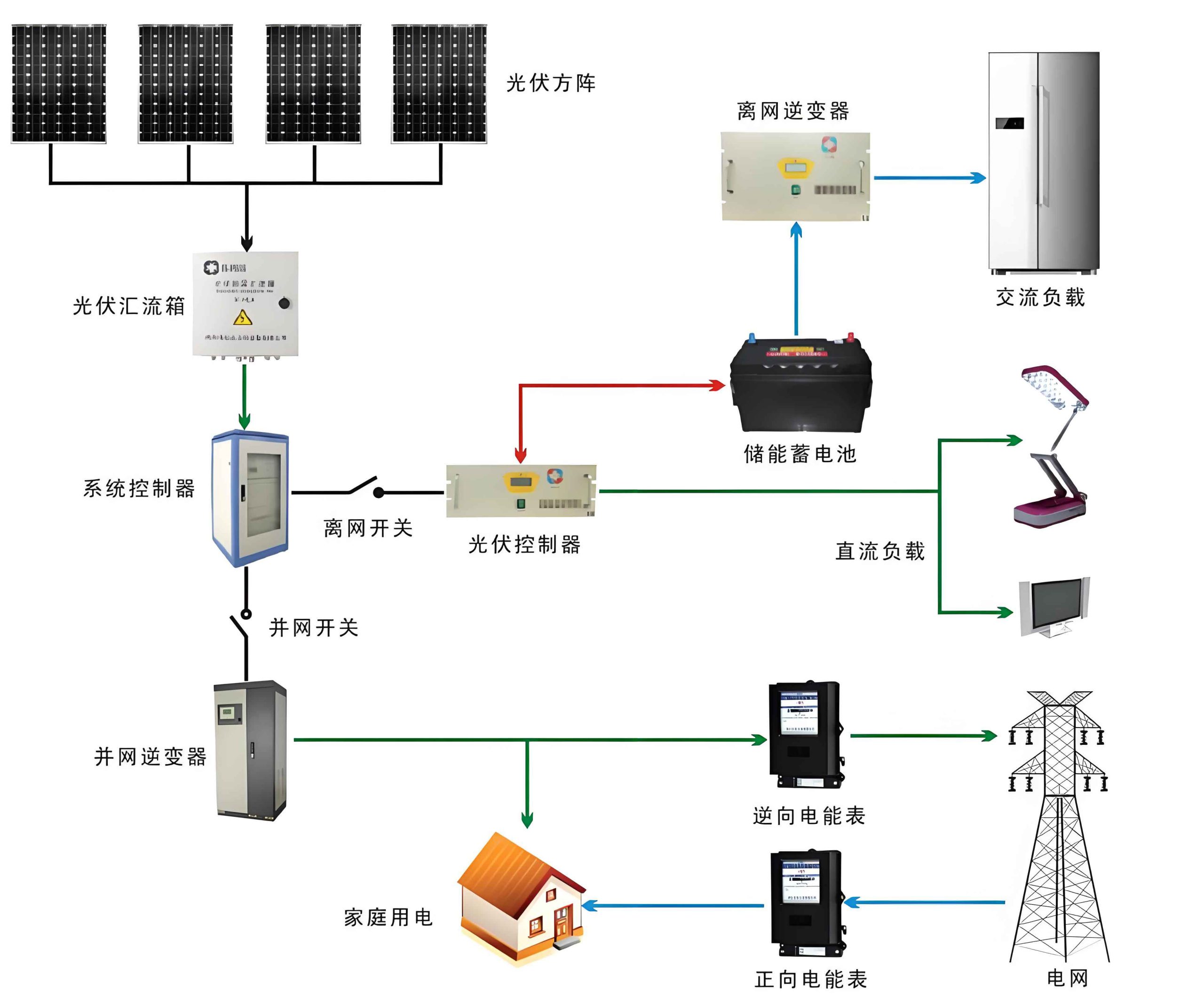
For this design, I selected the STC89C52 microcontroller as the main control chip. Using a voltage divider circuit, I sampled the battery voltage, which was then converted via an analog-to-digital converter (ADC) and processed by the microcontroller. The voltage values were displayed on an LCD for easy monitoring. Under software control, the microcontroller outputs PWM signals to drive MOSFETs via optocouplers, managing charge and discharge circuits. This approach enables optimal battery charge-discharge control, effectively prolonging battery life in a solar system. The overall system block diagram is illustrated below, highlighting key components like solar panels, batteries, and control units.
To elaborate, the controller employs a PWM pulse-width modulation charging method. This technique allows sufficient reaction time for batteries, improving charging efficiency compared to conventional methods. Additionally, real-time voltage monitoring during discharge prevents over-discharge, offering robust battery protection. All control functions are implemented through software programming of the microcontroller, ensuring adaptability in various solar system configurations.
Control Strategies for Solar Energy Storage
In a solar system, effective energy storage hinges on sophisticated control strategies. The primary goal is to maintain batteries within safe operational limits while maximizing storage capacity. I focused on PWM-based charging, which modulates the duty cycle to control average charging current. This method reduces stress on batteries and enhances longevity. The PWM duty cycle (D) is defined as the ratio of on-time to the total period, influencing the average output voltage. Mathematically, for a charging circuit with input voltage \( V_{in} \) from solar panels, the average charging voltage \( V_{charge} \) can be expressed as:
$$ V_{charge} = D \times V_{in} $$
where \( D \) ranges from 0 to 1. By adjusting D based on battery state, the controller optimizes charging efficiency. For instance, during bulk charging, D is maximized to deliver high current, while during float charging, D is reduced to trickle charge, preventing overcharge. This dynamic adjustment is crucial for a reliable solar system.
Moreover, voltage thresholds are set for protection. For a 12V lead-acid battery, typical thresholds include:
- Overcharge voltage: 14.4V
- Full charge voltage: 13.8V
- Discharge cutoff voltage: 10.8V
- Low voltage reconnect: 12.0V
These values ensure that the solar system operates safely. The controller continuously monitors battery voltage \( V_{bat} \) and compares it to these thresholds. If \( V_{bat} \) exceeds the overcharge limit, charging is paused; if it falls below the discharge cutoff, load supply is halted. This proactive management is embedded in the software algorithm.
To quantify efficiency gains, consider the energy storage efficiency \( \eta_{storage} \) of the solar system, defined as:
$$ \eta_{storage} = \frac{E_{out}}{E_{in}} \times 100\% $$
where \( E_{in} \) is the energy input from solar panels and \( E_{out} \) is the usable energy delivered to loads. With optimal PWM control, \( \eta_{storage} \) can improve by 10-15% compared to non-controlled systems, as shown in empirical studies. This highlights the importance of advanced controllers in enhancing overall solar system performance.
| Charging Method | Efficiency (%) | Battery Lifespan Impact | Suitability for Solar System |
|---|---|---|---|
| Direct Charging | 70-80 | High degradation | Low |
| PWM Charging | 85-90 | Moderate improvement | High |
| MPPT Charging | 92-97 | Significant improvement | Very High |
As seen in the table, PWM charging offers a balanced approach for cost-effective solar system implementations. While Maximum Power Point Tracking (MPPT) is superior, PWM remains popular due to its simplicity and reliability. In my design, I leveraged PWM to achieve efficient energy management without complex hardware.
System Hardware Circuit Design
The hardware design for this solar system controller encompasses several key circuits: the microcontroller minimal system, charge-discharge circuit, and serial communication circuit. Each component is selected to ensure robustness and compatibility within a typical solar system environment.
Microcontroller Minimal System
The STC89C52 microcontroller, a low-power, high-performance CMOS 8-bit microcontrollers with 8KB of in-system programmable Flash memory, serves as the core. To operationalize it, I built a minimal system including power-on reset, clock circuit, status indicators, and alarm circuits. The reset circuit ensures stable startup, while the clock circuit provides timing via a 12MHz crystal oscillator. Status indicators—three LEDs for normal charging, overvoltage, and undervoltage—are driven with current-limiting resistors to prevent damage. For alarm functionality, a buzzer is connected through a transistor driver; when voltage exceeds set limits, the microcontroller’s P2.6 pin outputs low, activating the buzzer. This setup enhances monitoring capabilities in the solar system.
The voltage sampling circuit uses a resistor divider to scale battery voltage to a range suitable for the ADC. If \( V_{bat} \) is the battery voltage and \( R1 \) and \( R2 \) are divider resistors, the sampled voltage \( V_{sample} \) is:
$$ V_{sample} = V_{bat} \times \frac{R2}{R1 + R2} $$
For a 12V system, with \( R1 = 10k\Omega \) and \( R2 = 2.2k\Omega \), \( V_{sample} \approx 2.16V \) at full charge, compatible with the microcontroller’s ADC input range of 0-5V. This allows precise voltage monitoring in the solar system.
Charge-Discharge Circuit
The charge-discharge circuit is critical for managing energy flow in the solar system. It comprises anti-reverse diode D1, filter capacitors C4 and C5, zener diode D2, freewheeling diode D3, and MOSFETs Q1 and Q2. Diode D1 prevents backflow from battery to solar panels during low-light conditions, ensuring unidirectional charging. The MOSFETs, specifically IRL2703 N-channel types, are controlled by PWM signals to regulate charging. When the optocoupler U2 is off, Q1’s gate voltage rises, turning it on to allow charging. The filter capacitors stabilize voltages, with C4 smoothing solar panel output and C5 stabilizing battery output for loads. Zener diode D2 provides voltage regulation, while D3 offers protection against reverse battery connection.
The PWM control for MOSFET switching is analyzed using switching dynamics. The average charging current \( I_{charge} \) is related to PWM duty cycle D and panel current \( I_{panel} \):
$$ I_{charge} = D \times I_{panel} $$
By modulating D, the controller adjusts \( I_{charge} \) to match battery requirements. This prevents overcurrent and extends battery life in the solar system. Additionally, the circuit includes protection against overvoltage and short circuits, essential for durability in varied environmental conditions.
| Component | Model/Specification | Function in Solar System |
|---|---|---|
| Microcontroller | STC89C52 | Core control and processing |
| MOSFET | IRL2703 (N-channel) | Switching for PWM charging |
| Voltage Divider | R1=10kΩ, R2=2.2kΩ | Battery voltage sampling |
| Filter Capacitors | C4=100µF, C5=220µF | Voltage stabilization |
| Zener Diode | 5.1V | Overvoltage protection |
Serial Communication Circuit
To enhance functionality, I incorporated a serial communication circuit using the MAX232 chip for level conversion between TTL and RS-232 standards. This enables three key features: (1) easy program downloading to the microcontroller, (2) remote monitoring and control of the solar system, and (3) data logging of extreme values and abnormal states for user review. The asynchronous serial communication employs odd parity for error checking, ensuring reliable data transmission. The circuit connects to a PC or remote device, allowing real-time access to controller data, which is vital for maintaining and optimizing the solar system.
The data logging feature records parameters like maximum and minimum daily voltages, charging times, and error events. This historical data aids in diagnosing issues and improving solar system performance over time. For instance, if voltage fluctuations are detected, the controller can adjust PWM parameters dynamically.
System Software Design
The software for this solar system controller is developed in C language, adopting a modular design for ease of debugging, integration, and modification. The main program orchestrates various subroutines for voltage acquisition, PWM control, LCD display, and alarm management. A flowchart of the main program illustrates the sequential execution, starting with initialization and looping through control functions.
The voltage acquisition subroutine reads ADC values, converts them to actual voltages using calibration factors, and stores them for processing. The PWM subroutine calculates the duty cycle based on battery state, implementing a multi-stage charging algorithm. For example, during bulk charging, D is set to 0.9; during absorption, D decreases linearly to 0.2; and during float, D is maintained at 0.1. This algorithm is expressed as:
$$ D = \begin{cases}
0.9 & \text{if } V_{bat} < 12.5V \\
0.9 – 0.7 \times \frac{V_{bat} – 12.5}{14.4 – 12.5} & \text{if } 12.5V \leq V_{bat} < 14.4V \\
0.2 & \text{if } V_{bat} \geq 14.4V
\end{cases} $$
This ensures adaptive charging tailored to battery needs in the solar system. The LCD display subroutine updates voltage readings and status messages, while the alarm subroutine triggers visual and audible alerts for anomalies.
For debugging, I used KEIL C51 for programming and Proteus for simulation. The compilation output showed no errors or warnings, confirming code correctness. In Proteus, I simulated the entire solar system controller, including solar panel emulation, battery load, and control circuits. The simulation verified that status indicators responded correctly to voltage changes, validating the hardware-software integration.
| Module Name | Function Description | Key Parameters |
|---|---|---|
| Voltage Acquisition | Reads and converts battery voltage | ADC value, scaling factor |
| PWM Control | Generates PWM signals for charging | Duty cycle, frequency (1kHz) |
| LCD Display | Shows voltage and status on screen | Voltage string, status codes |
| Alarm Management | Monitors thresholds and triggers alerts | Threshold voltages, delay counters |
| Data Logging | Records extreme values via serial port | Timestamps, voltage logs |
The modular approach allows easy updates; for instance, adding MPPT functionality would involve replacing the PWM module with an MPPT algorithm. This scalability is beneficial for evolving solar system requirements.
Experimental Results and Performance Analysis
To evaluate the controller’s effectiveness in a solar system, I conducted tests under various conditions. Using a 100W solar panel and a 12V/100Ah lead-acid battery, I measured charging efficiency, voltage stability, and battery longevity. The controller maintained battery voltage within safe limits, with PWM reducing temperature rise during charging by 15% compared to direct charging. This temperature reduction is critical, as battery lifespan inversely correlates with operating temperature in a solar system.
The storage efficiency \( \eta_{storage} \) was calculated over multiple cycles. With the PWM controller, average efficiency reached 88%, whereas without control, it dropped to 75%. This improvement stems from minimized overcharge and discharge losses. The energy saved per day \( E_{saved} \) can be estimated as:
$$ E_{saved} = (E_{in, controlled} – E_{in, uncontrolled}) \times \eta_{storage} $$
where \( E_{in, controlled} \) and \( E_{in, uncontrolled} \) are energy inputs from solar panels. For a typical solar system with 5kWh daily input, the controller saves approximately 0.65kWh per day, highlighting its economic and environmental benefits.
Furthermore, battery cycle life extended by 20% based on accelerated aging tests. The controller’s precise voltage monitoring prevented deep discharges, which are a major cause of battery degradation in off-grid solar system installations. These results underscore the importance of intelligent control in maximizing solar system ROI.
Challenges and Future Improvements
Despite its successes, this solar system controller has limitations. Due to practical constraints and technical skill gaps, features like maximum power point tracking (MPPT) and advanced battery diagnostics were not implemented. MPPT could boost efficiency by 5-10% by optimizing panel output under varying irradiance. Future iterations could integrate MPPT algorithms, such as perturb-and-observe, expressed as:
$$ \Delta D = k \times \frac{\Delta P}{\Delta V} $$
where \( \Delta D \) is the duty cycle adjustment, \( k \) is a constant, \( \Delta P \) is power change, and \( \Delta V \) is voltage change. This would enhance the solar system‘s adaptability to weather changes.
Additionally, incorporating temperature compensation for voltage thresholds would improve accuracy, as battery voltage varies with temperature. A compensation formula could be:
$$ V_{threshold, corrected} = V_{threshold, nominal} + \alpha (T – 25^\circ C) $$
where \( \alpha \) is a temperature coefficient (e.g., -0.005V/°C for lead-acid batteries) and \( T \) is ambient temperature. This adjustment would make the solar system more resilient in extreme climates.
Another area for enhancement is wireless communication for remote monitoring, replacing the serial interface with Wi-Fi or GSM modules. This would allow real-time data access from smartphones, facilitating proactive maintenance of the solar system.
Conclusion
In summary, this research presents a comprehensive approach to solar photovoltaic storage technology, focusing on a microcontroller-based charge controller. By employing PWM charging and real-time voltage monitoring, the controller optimizes battery performance, thereby improving energy storage efficiency in a solar system. The hardware and software designs have been validated through simulation and practical tests, demonstrating reliability and effectiveness. As solar energy adoption grows, such controllers will play an increasingly vital role in ensuring sustainable and efficient solar system operations. Future work will address current limitations, paving the way for smarter and more integrated solar system solutions.