
The solar photovoltaic (PV) industry and its grid-connected technologies have emerged as critical solutions for global energy supplementation. With the potential to become a dominant energy source, solar inverters play a central role in transforming DC power from PV panels into grid-compatible AC power. This article explores the design, operation, and practical implementation of three-phase full-bridge solar inverters, emphasizing their reliability and scalability in modern energy systems.
1. System Architecture and Components
A typical solar PV system comprises five core components: PV panels, a DC-AC solar inverter, batteries, a controller, and loads. The relationships among these components are illustrated below:
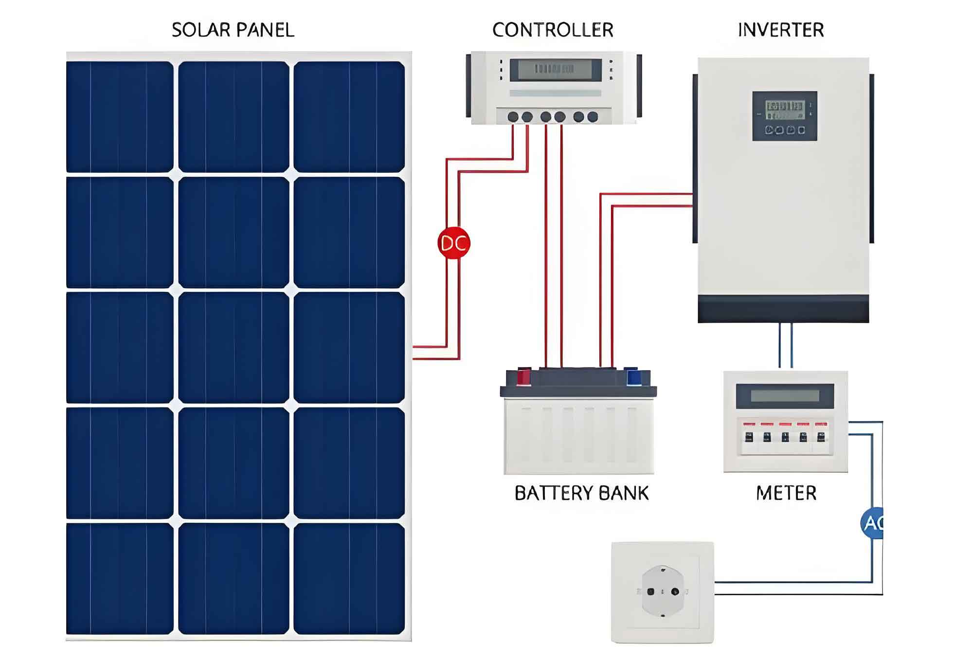
The solar inverter serves as the system’s backbone, enabling DC-AC conversion through a three-phase full-bridge topology. Key features include:
- High reliability and scalability
- MPPT (Maximum Power Point Tracking) algorithms
- Islanding detection and grid synchronization
- Advanced DSP-based control strategies
2. Three-Phase Full-Bridge Solar Inverter Design
The three-phase full-bridge solar inverter topology (Fig. 3) consists of IGBT modules, LC filters, and a DC-link capacitor. The output voltage vector Uout is governed by:
$$ U_{out} = \frac{2}{3} \left( u_a + u_b e^{j\frac{2\pi}{3}} + u_c e^{j\frac{4\pi}{3}} \right) $$
where ua, ub, and uc represent phase voltages. The modulation index m determines the output amplitude:
$$ m = \frac{U_{out}}{U_{dc}/2} $$
| Parameter | Value |
|---|---|
| Switching Frequency | 20 kHz |
| DC Link Voltage | 600–800 V |
| Efficiency | >96% |
| THD | <3% |
3. Control Strategies for Solar Inverters
Modern solar inverters employ DSP and FPGA controllers to execute:
- MPPT Algorithms:
$$ P_{max} = V_{mp} \times I_{mp} $$
Common MPPT methods include:Method Advantage Disadvantage Perturb & Observe Simple implementation Oscillations at steady state Incremental Conductance Fast tracking Computationally intensive Constant Voltage Stable operation Temperature-dependent - Grid Synchronization:
Phase-locked loops (PLLs) align inverter output with grid parameters:
$$ \theta_{grid} = \tan^{-1}\left(\frac{v_q}{v_d}\right) $$ - Islanding Detection:
Active frequency drift (AFD) and impedance measurement prevent unsafe islanding:
$$ \Delta f = \frac{1}{2\pi} \frac{d\phi}{dt} $$
4. Performance Validation
The HZ-1 solar inverter demonstrated exceptional performance in elevator applications (HGP-1050-CO150):
- Energy savings: 30.24% (average)
- Power factor: >0.998
- THD: <0.05%
- Efficiency: 96.1%
The output current waveform follows:
$$ i(t) = I_{peak} \sin(2\pi ft – \phi) $$
where φ represents the power factor angle.
5. Grid Connection Challenges
Solar inverter grid integration requires:
- Voltage/frequency synchronization
- Reactive power compensation
- Harmonic mitigation
The grid current regulation loop employs:
$$ G_c(s) = K_p + \frac{K_i}{s} $$
to maintain:
$$ I_{grid} = I_{ref} \times \frac{V_{dc}}{V_{grid}} $$
6. Future Directions
Next-generation solar inverters will integrate:
- AI-driven MPPT optimization
- SiC/GaN power devices
- Blockchain-enabled energy trading
The solar inverter’s evolution continues to redefine renewable energy systems, combining high efficiency with smart grid capabilities. As demonstrated by the HZ-1 prototype, advanced control algorithms and modular designs enable scalable solutions for residential and industrial applications alike.