
At present, gasoline powered cars are still the main source of global automobiles, leading to a continuous increase in oil consumption and a series of problems such as air pollution, greenhouse gas emissions, and global warming. Pure electric vehicles are an inevitable trend in the future development of the automotive industry. As energy storage components of electric vehicle infrastructure and vehicle electrification technology, they have attracted widespread attention from scholars at home and abroad.
Energy storage components are one of the key components of pure electric vehicles, which need to meet both the energy density and power density requirements of the vehicle. Among them, energy density refers to the sustained and stable energy supply required by a car in low-speed and cruise modes; And power density determines the instantaneous power supply and absorption of the car in acceleration and regenerative braking modes. Usually, there is an inverse relationship between the energy density and power density of energy storage components, that is, as the energy density increases, its power density decreases. For example, power batteries generally have a higher energy density, but their power density is lower; Supercapacitors have a higher power density, but their energy density is lower. To break the contradiction between energy and power and meet the dual needs of pure electric vehicles for high energy density and high power density, power batteries and supercapacitors can be combined, specifically connected through power converters. The combined power battery, supercapacitor, and power converter are defined as a hybrid energy storage system.
Due to the difference in the number and placement of power converters, it directly leads to differences in the topology of hybrid energy storage system. At present, domestic and foreign scholars have conducted comparative studies on the complexity, maximum power output capability, and control flexibility of hybrid energy storage system with different topology structures. However, there is relatively little research on the reliability assessment of hybrid energy storage system.
High reliability is one of the key issues in the design and manufacturing of automotive hybrid energy storage system, therefore, comparative research on the reliability evaluation of hybrid energy storage system with different topological structures is of great significance. This article starts from the perspective of reliability, based on Markov chains and Bayesian networks, establishes reliability models for vehicle hybrid energy storage system with different topological structures, obtains the failure rates of each topological structure hybrid energy storage system, and ranks them according to reliability levels.
1. The working mechanism of hybrid energy storage system with different topological structures
As shown in Figures 1 to 5, there are five different topological structures of hybrid energy storage system.
Figure 1 shows the passive structure of a power battery directly connected in parallel with a supercapacitor. The function of the bidirectional DC/DC converter in this structure is to increase the hybrid energy storage system voltage level to the DC bus voltage level required by the motor drive components and maintain stability, so that the motor can obtain the required energy and power. The advantage of passive hybrid energy storage system lies in its simple structure and easy implementation; The disadvantage is that the power battery and supercapacitor belong to two different energy storage components with different characteristics. Direct parallel connection leads to the inability to control the charging and discharging states and depths of the two separately, and the voltage characteristics of the power battery are relatively hard, while the voltage characteristics of the supercapacitor are relatively soft. The direct parallel connection of the two limits the power throughput capacity of the supercapacitor. Therefore, passive structure hybrid energy storage system has no practical application value for pure electric vehicles.
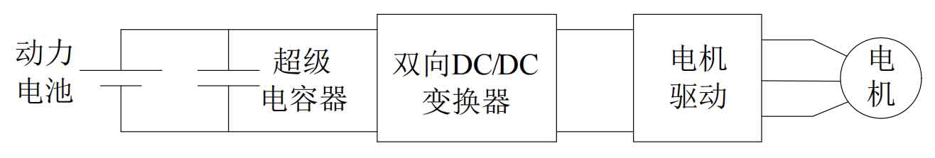
Figure 2 shows a cascaded structure hybrid energy storage system with supercapacitors located in the middle position. Compared to the passive structure hybrid energy storage system, the bidirectional DC/DC converter 1 is located between the power battery and supercapacitor, so the charging and discharging status and depth of the power battery and supercapacitor can be controlled separately. In addition, since supercapacitors need to provide the high power density required for motor loads, their voltage changes depend on the changes in the state of charge, and the amplitude of the changes is large. Therefore, the role of bidirectional DC/DC converter 2 is to regulate and stabilize the DC bus voltage.
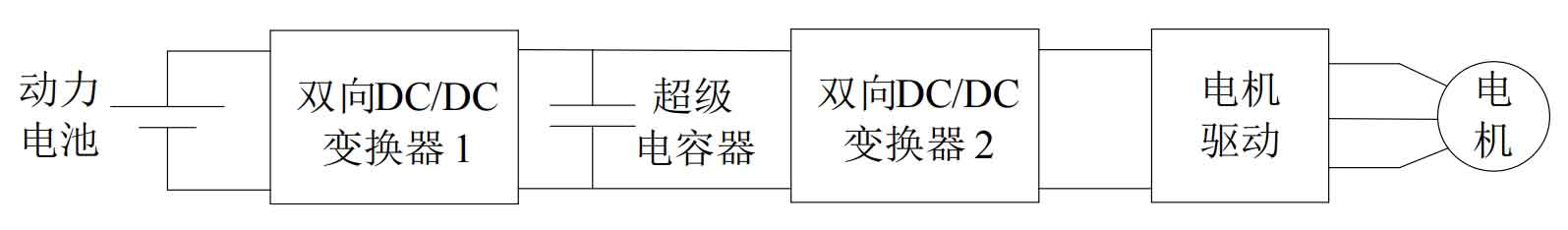
Figure 3 shows another cascaded structure hybrid energy storage system with a power battery located in the middle position. In this structure, the supercapacitor is connected to the power battery through a bidirectional DC/DC converter 1. The voltage levels of the two energy storage components do not need to be consistent, and the power throughput capacity of the supercapacitor is controllable at any time. The connection between the power battery and the bidirectional DC/DC converter 2 makes it easier to achieve the goal of stabilizing the DC bus voltage, thereby solving the problem of voltage variation in the structure shown in Figure 2. In addition, since the rated voltage of the battery pack is usually lower than the DC bus voltage, the function of bidirectional DC/DC converter 2 is to increase the battery pack voltage to the set DC bus voltage level.
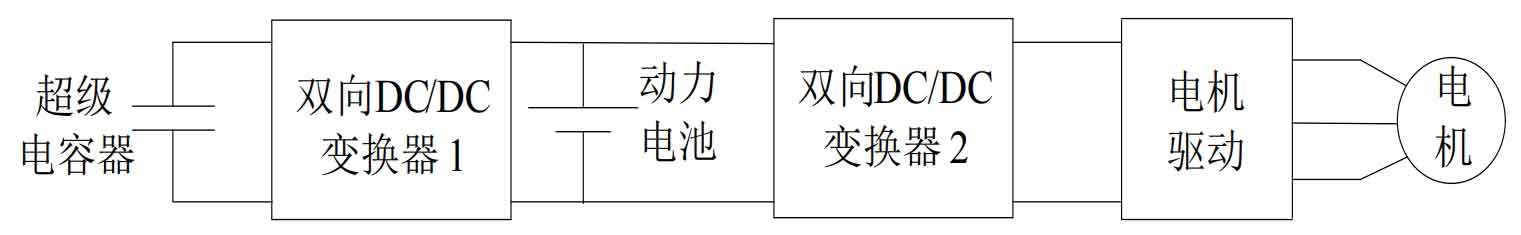
Figure 4 shows a parallel structure hybrid energy storage system. It is called a parallel structure because the power battery and supercapacitor in this structure are connected in parallel to the DC bus voltage through a bidirectional DC/DC converter. The supercapacitor and bidirectional DC/DC converter 1 are responsible for providing the high power density required for the motor load; The power battery and bidirectional DC/DC converter 2 are responsible for providing the high energy density required by the load, while regulating and stabilizing the DC bus voltage. The regulation of the two energy storage components in the parallel structure hybrid energy storage system is independent and does not interfere with each other, which can fully leverage the advantages of the power battery and supercapacitor.
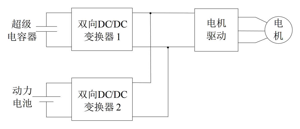
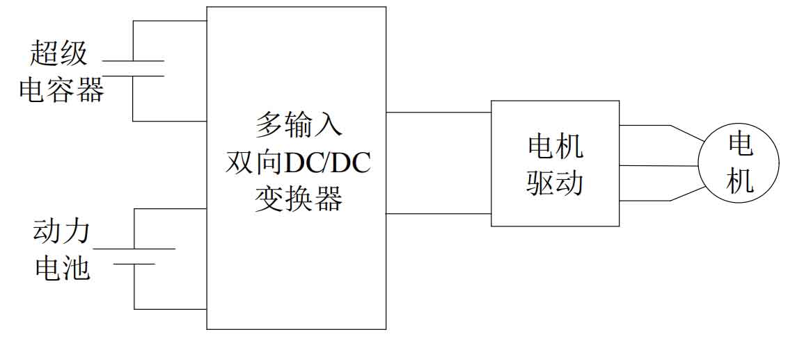
Figure 5 shows the hybrid energy storage system connected by a multi input bidirectional DC/DC converter between the power battery and supercapacitor. A multi input bidirectional DC/DC converter can achieve the functionality of the two bidirectional DC/DC converters shown in Figure 4, thereby reducing the complexity of the hybrid energy storage system system while reducing cost and volume.
2. Reliability evaluation of hybrid energy storage system with different topological structures
Based on the above, due to the fundamental flaws of the passive structure hybrid energy storage system, it is not suitable for the field of pure electric vehicles in industry. Therefore, this article does not model the reliability of the passive structure hybrid energy storage system and does not consider its reliability research.
2.1 Reliability evaluation of cascaded hybrid energy storage system with supercapacitors located in the middle position
As shown in Figure 6, the state transition diagram of a cascaded hybrid energy storage system with supercapacitors located in the middle position is based on Markov chain theory. Among them: State 1 represents the initial state of all hybrid energy storage system modules during operation; State 2 indicates that the supercapacitor has malfunctioned. In this state, due to the lack of supercapacitors, the hybrid energy storage system operates under poor performance conditions; State 3 indicates that whether there is a fault in the power battery, bidirectional DC/DC converter 1, or bidirectional DC/DC converter 2, the system will be in a paralyzed state. Figure 6 also shows the transition rates between different states. Among them: λ UC is the failure rate of supercapacitors; λ BC1 and λ BC2 represents the failure rates of bidirectional DC/DC converter 1 and bidirectional DC/DC converter 2, respectively; λ Batt is the failure rate of the power battery.
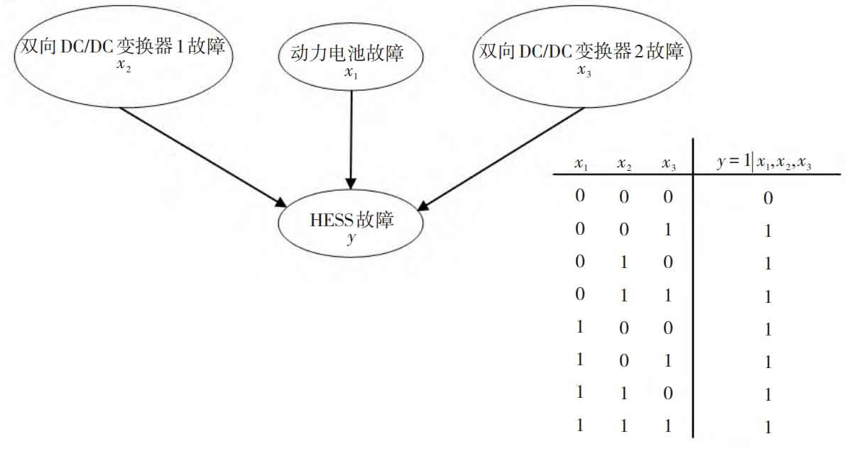
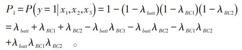
From Figure 6, it can be observed that the ultimate factor causing the failure of the cascaded hybrid energy storage system system with the supercapacitor located in the middle position is the failure of either the power battery, bidirectional DC/DC converter 1, or bidirectional DC/DC converter 2. As shown in Figure 7, it is a Bayesian network model diagram of the hybrid energy storage system structure, which includes two parts: a directed acyclic graph and a conditional probability table. In Figure 7, assuming that the failure of the power battery, bidirectional DC/DC converter 1, bidirectional DC/DC converter 2, and hybrid energy storage system is represented by events x1, x2, x3, and y, respectively, the failure rate P1 of the hybrid energy storage system structure can be expressed as:
2.2 Reliability evaluation of cascaded hybrid energy storage system with power batteries located in the middle position
As shown in Figure 8, the Markov chain state transition diagram of the cascaded structure hybrid energy storage system with the power battery located in the middle position. Among them: State 1 is the initial state, indicating that all modules of hybrid energy storage system are normal; If the supercapacitor or bidirectional DC/DC converter 1 fails, the Markov chain transitions from state 1 to state 2 and state 3, respectively; In states 2 and 3, hybrid energy storage system can still withstand another fault. For example, if a fault occurs in the supercapacitor in state 2, followed by a fault in bidirectional DC/DC converter 1, the Markov chain will transition from state 2 to state 4, but the hybrid energy storage system can still operate at this time; Similarly, in state 3, bidirectional DC/DC converter 1 fails, and the failure of the supercapacitor transfers the Markov chain from state 3 to state 5. However, regardless of which state the Markov chain is in, if either the power battery or bidirectional DC/DC converter 2 fails, the Markov chain will transition to state 6, and the entire hybrid energy storage system will be paralyzed.
In Figure 8, λ Batt+ λ BC2 is composed of λ Simplify T. It is not difficult to see that the ultimate factor causing the failure of the cascaded hybrid energy storage system with the power battery in the middle position is the failure of either the power battery or the bidirectional DC/DC converter 2. As shown in Figure 9, is the Bayesian network model diagram of the HESS structure.
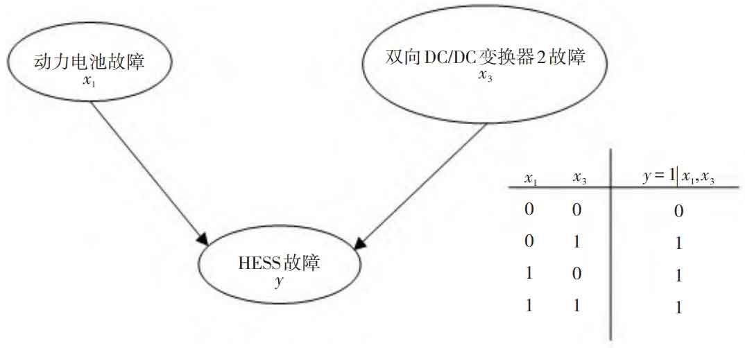
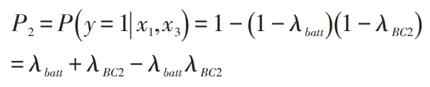
According to Figure 9, the failure rate P2 of the hybrid energy storage system structure can be expressed as:
2.3 Reliability evaluation of parallel structure hybrid energy storage system
As shown in Figure 10, the Markov chain state transition diagram of the parallel structure hybrid energy storage system. Among them, state 1 and state 3 represent the initial state (normal state) and final state (paralyzed state), respectively; State 2 means that either or both of the supercapacitor and bidirectional DC/DC converter 1 have failed. At this time, the hybrid energy storage power supply is not operating in the optimal working state, but can still operate normally. It can be seen that due to parallel connection, the faults of the supercapacitor and bidirectional DC/DC converter 1 do not affect the normal operation of the power battery. Therefore, regardless of the state of the Markov chain, the entire system can only be paralyzed if the power battery or bidirectional DC/DC converter 2 fails. The Bayesian network model diagram of the parallel structure hybrid energy storage system is the same as the Bayesian network model diagram of the cascaded structure hybrid energy storage system with the power battery located in the middle position, as shown in Figure 9.
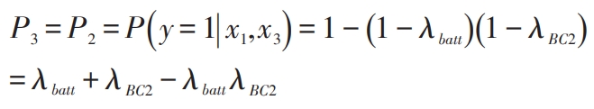
The failure rate P3 of the parallel structure hybrid energy storage system can be described as:
2.4 Reliability evaluation of multi input power converter structure hybrid energy storage system
As shown in Figure 11, the Markov state transition diagram of the multi input power converter structure hybrid energy storage system. The fault rate of a multi input bidirectional power converter is defined as λ MIC. State 1 is the initial state. If the supercapacitor malfunctions, the Markov chain transitions to state 2, and at this point, the hybrid energy storage system can still operate normally. Due to the fact that the power battery and supercapacitor are connected to the DC bus through multiple input power converters, the multiple input power converter is the only point of failure for the HESS system. Namely, regardless of the state of the Markov chain, a fault in the multi input power converter will transfer the Markov chain to state 3, causing the system to become paralyzed.
According to Figure 11, the ultimate factor causing the failure of the multi input power converter structure hybrid energy storage system system is the failure of either the power battery or the multi input bidirectional DC/DC converter. Let the fault representation event x4 be generated by the multi input bidirectional DC/DC power converter, as shown in Figure 12, which is the Bayesian network model diagram of the hybrid energy storage system structure.
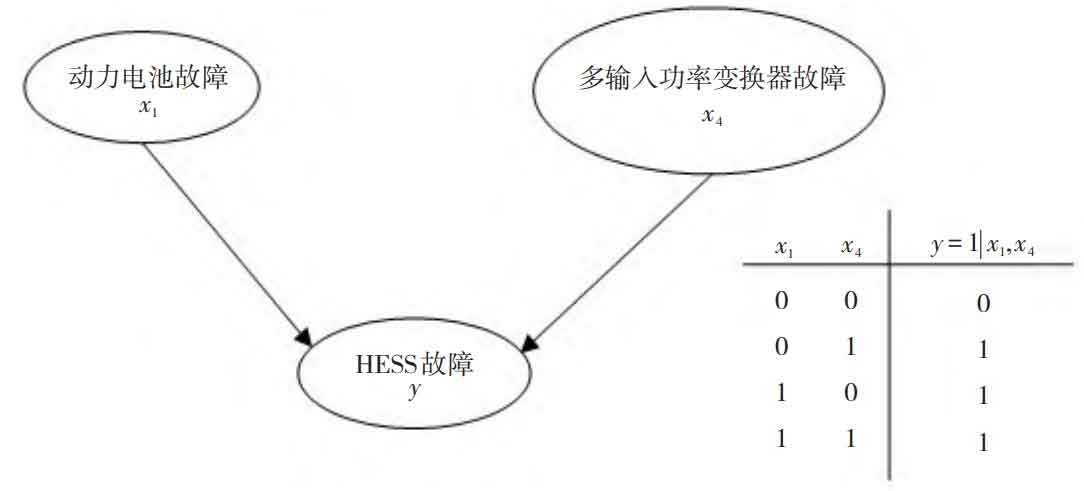
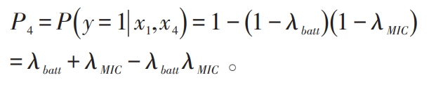
The fault rate P4 of the multi input power converter structure hybrid energy storage system can be expressed as:
2.5 Reliability Comparison of hybrid energy storage system with Different Topological Structures
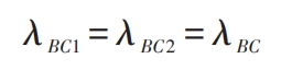
For reasonable comparison, it is assumed that the fault rate of the same bidirectional DC/DC converter in hybrid energy storage system with different topological structures is the same, that is:
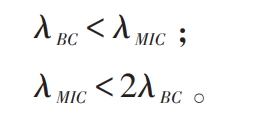
In addition, it should be noted that the failure rate of bidirectional DC/DC converters depends on the number of internal electronic components. Power converters with more electronic components have poorer reliability, so there are:
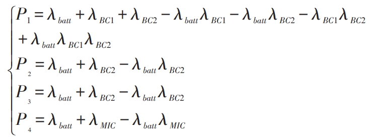
Therefore, based on the formula, the failure rates of hybrid energy storage system with different topological structures are formed into a system of equations, namely:
Based on practical engineering experience, the failure rate of each module in hybrid energy storage system is generally less than 50%, otherwise it has no practical application value. In this case, by comparing the failure rates of four different structures of hybrid energy storage system, it can be concluded that:
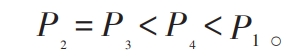
As shown in Table 1, based on the formula, the reliability of four different topology structures of hybrid energy storage system is ranked: the cascaded structure hybrid energy storage system with supercapacitors located in the middle has the worst reliability; The reliability of the multi input power converter structure hybrid energy storage system is better than the former; The cascaded structure hybrid energy storage system and parallel structure hybrid energy storage system with power batteries located in the middle position have the strongest reliability.
| The topological structure of the Hybrid energy storage system | Corresponding figure | Failure rate | Reliability ranking |
| Cascade structure with supercapacitors located in the middle position | Figures 2, 6, and 7 | P1 | 3 |
| Cascade structure with power battery located in the middle position | Figures 3, 8, and 9 | P2 | 1 |
| Parallel structure | Figures 4, 9, and 10 | P3 | 1 |
| Multi input power converter structure | Figures 5, 11, and 12 | P4 | 2 |
4. Conclusion
A reliability evaluation method for hybrid energy storage power sources for vehicles with different topological structures based on Markov chains and Bayesian networks is proposed. By briefly analyzing the working mechanisms of five different hybrid energy storage power sources for vehicles with different structures, a reliability evaluation was conducted, and the following conclusions were drawn:
(1) The most reliable are the cascaded structure hybrid energy storage system and parallel structure hybrid energy storage system with power batteries located in the middle position, followed by the multi input power converter structure hybrid energy storage system;
(2) The cascaded structure hybrid energy storage system with supercapacitors located in the middle position has the worst reliability.
The reliability of hybrid energy storage system with different topological structures has been analyzed from a theoretical perspective. However, there are also some other factors that affect reliability in actual circuits, such as voltage and current stress of different devices. We plan to analyze a large number of actual circuits in the future, and after obtaining experimental data, further evaluate the reliability of the top two different topology structures of hybrid energy storage system.