
In the realm of power communication systems, ensuring uninterrupted operation of critical equipment is paramount. The reliance on 48V DC power systems, typically composed of high-frequency switching power supplies and lead-acid batteries, presents vulnerabilities during maintenance, faults, or upgrade operations. Frequent power interruptions at communication sites can lead to service disruptions, affecting the entire network’s stability. To address this, we have developed a portable, safe, and scalable emergency power solution. This article delves into the design, implementation, and testing of a portable 48V DC emergency power supply based on lithium iron phosphate (LiFePO4) batteries. The LiFePO4 battery technology is chosen for its superior energy density, stability, and safety profile, making it ideal for field applications. We explore the structural design, protection mechanisms, parallel expansion capabilities, and performance metrics of this system. The goal is to provide communication maintenance teams with a reliable, flexible tool that can be deployed swiftly during emergencies, ensuring continuity of essential services such as dispatching data networks, telephony, and relay protection communications.
The core of any portable emergency power supply is its energy storage unit. We evaluated three prevalent battery technologies: lead-acid, ternary lithium, and LiFePO4 batteries. Lead-acid batteries are widely used in power communication systems due to their cost-effectiveness and proven reliability. However, their low energy density results in heavy and bulky units, compromising portability. Ternary lithium batteries offer high energy density but suffer from thermal instability and stringent management requirements, posing safety risks. In contrast, the LiFePO4 battery strikes an optimal balance. Its energy density is significantly higher than lead-acid, enabling compact and lightweight designs. Moreover, its chemical stability minimizes risks of thermal runaway, making it safer for field use. The following table summarizes the key characteristics of these battery types, highlighting why the LiFePO4 battery is the preferred choice for our portable emergency power supply.
| Battery Technology | Specific Energy (Wh/kg) | Cycle Life (Cycles) | Thermal Stability | Cost per kWh | Suitability for Portable Use |
|---|---|---|---|---|---|
| Lead-Acid | 30-50 | 200-500 | High | Low | Low (Heavy) |
| Ternary Lithium (NMC) | 150-220 | 500-1500 | Moderate to Low | Medium to High | Medium (Safety Concerns) |
| LiFePO4 (LFP) | 90-160 | 2000-6000 | High | Medium | High (Optimal Balance) |
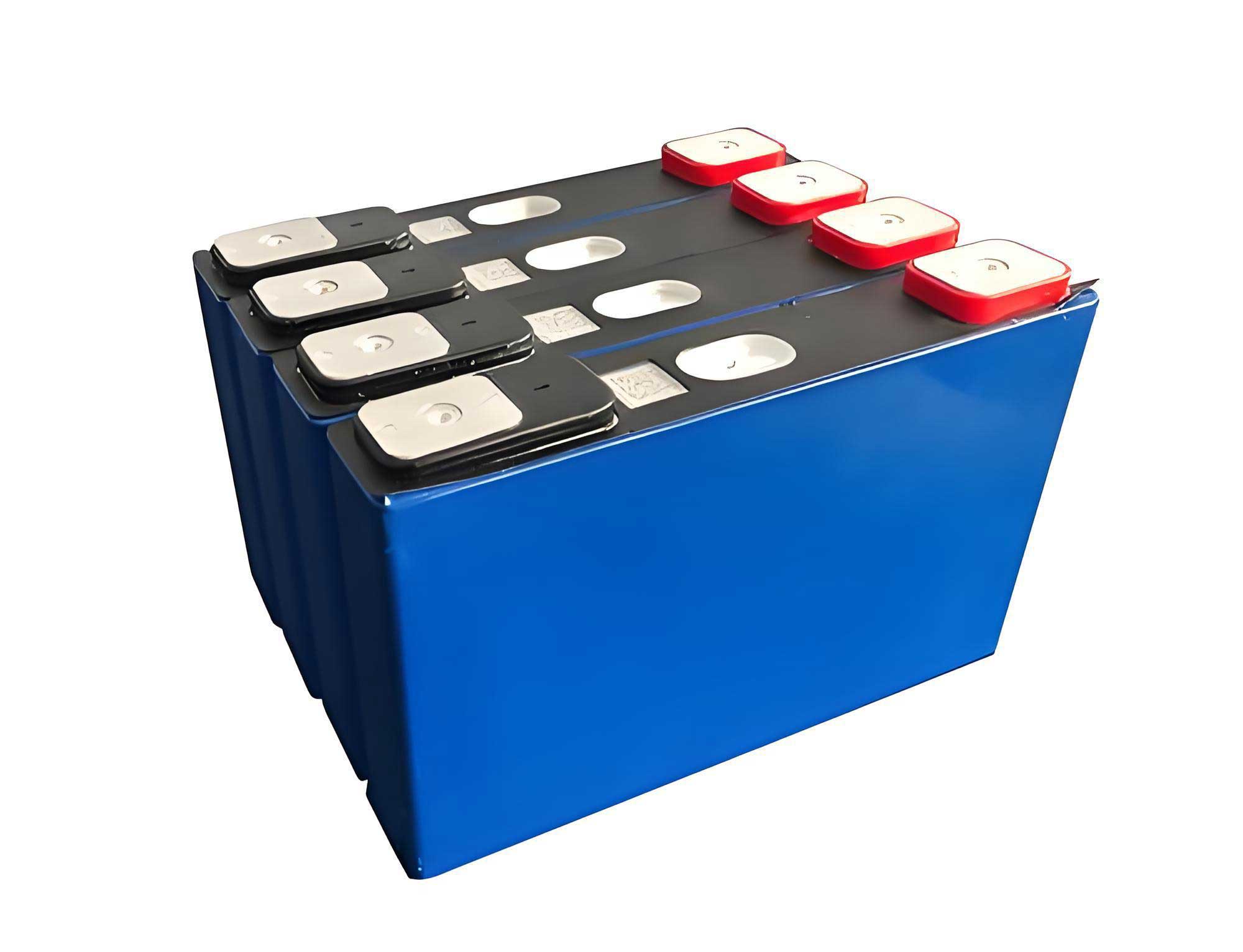
The electrochemical advantages of the LiFePO4 battery are rooted in its olivine crystal structure, which provides excellent structural stability during charge and discharge cycles. The operating voltage of a single LiFePO4 cell is approximately 3.2V, and its flat discharge curve ensures stable output. For a 48V system, we series-connected 16 such cells to form a battery pack. The nominal voltage is calculated as:
$$ V_{pack} = N_{cells} \times V_{cell} = 16 \times 3.2V = 51.2V \text{ (nominal, typically adjusted to 48V system compatibility)} $$
In practice, the pack is designed to operate within the 48V DC range, with charging and discharging profiles tailored to communication equipment standards. The energy capacity of the pack is determined by the cell capacity. For instance, using 20Ah cells, the total energy storage is:
$$ E_{pack} = V_{pack} \times C_{cell} = 51.2V \times 20Ah = 1024Wh $$
This high energy density directly translates to portability. A single unit, including the battery pack and circuitry, weighs under 13 kg, allowing easy transport by a single person. The use of LiFePO4 battery technology is thus foundational to achieving our design objectives of safety, reliability, and mobility.
The structural design of the portable emergency power supply integrates multiple protection and management circuits to ensure safe operation. The system architecture comprises several key modules: the LiFePO4 battery pack, a charging isolation circuit, a discharge isolation circuit, a monitoring circuit, and a short-circuit protection circuit. All these components are housed within a robust carbon fiber enclosure, which provides mechanical strength, lightweight properties, and additional safety containment in rare events of battery failure. The system block diagram is conceptualized as follows, with each module fulfilling a specific role.
The charging isolation circuit is designed to allow unidirectional energy flow from an external DC source (e.g., a station’s communication power system) to the LiFePO4 battery pack. It prevents any backflow of current from the battery to the external source, which could occur if the external voltage drops. This isolation is typically achieved using semiconductor switches like MOSFETs configured in a way that they only conduct during charging. The circuit also incorporates overcharge protection by monitoring the battery voltage and terminating charge when the upper limit is reached. The charging current \(I_{charge}\) is limited to a safe value, often 0.5C (where C is the battery capacity), to preserve battery life. For a 20Ah LiFePO4 battery pack, the charge current is set to 10A. The voltage relationship during charging can be expressed as:
$$ V_{source} = V_{bat} + I_{charge} R_{chg} + V_{fwd} $$
Here, \(V_{source}\) is the external source voltage (typically set to float charge at 55V or equalize charge at 56.4V in communication systems), \(V_{bat}\) is the instantaneous battery voltage, \(R_{chg}\) is the resistance in the charging path, and \(V_{fwd}\) is the forward voltage drop across isolation diodes or switches. The circuit ensures that \(V_{bat}\) never exceeds the maximum cell voltage, usually 3.65V per cell, summing to 58.4V for the pack. This meticulous control is crucial for the longevity and safety of the LiFePO4 battery.
The discharge isolation circuit functions similarly but in the opposite direction. It permits current to flow from the LiFePO4 battery pack to the connected communication load but blocks any reverse current that could attempt to charge the battery from the load side. This is vital when multiple emergency power units are paralleled or when the load is suddenly removed. The circuit often uses MOSFETs with body diodes oriented to allow discharge only. Additionally, it incorporates current balancing features when units are connected in parallel, ensuring each LiFePO4 battery pack shares the load proportionally. The output voltage during discharge is regulated to maintain stability within the 48V system tolerance, typically between 44V and 58V. The discharge current \(I_{discharge}\) is monitored, and the circuit adjusts to keep the output voltage \(V_{out}\) as steady as possible, following the relation:
$$ V_{out} = V_{bat} – I_{discharge} R_{dis} $$
where \(R_{dis}\) represents the internal resistance of the discharge path. The flat discharge curve of the LiFePO4 battery aids in maintaining \(V_{out}\) over a wide state-of-charge (SoC) range.
The monitoring circuit is a critical intelligence module. It continuously measures parameters such as battery voltage, current, temperature, and estimated state of charge (SoC). These data are accessible via a communication port (e.g., RS-485 or CAN bus) on the device enclosure, allowing field technicians to monitor the health and remaining capacity of the LiFePO4 battery. The SoC estimation is often performed using coulomb counting combined with voltage calibration. The algorithm can be summarized as:
$$ SoC(t) = SoC(t_0) – \frac{1}{C_{nom}} \int_{t_0}^{t} \eta I(\tau) d\tau $$
where \(C_{nom}\) is the nominal capacity (20Ah), \(I(\tau)\) is the instantaneous current (positive for discharge), and \(\eta\) is the coulombic efficiency (near 1 for LiFePO4 batteries). Voltage thresholds are used to reset the SoC at full charge and full discharge points, ensuring accuracy. This monitoring capability is essential for preventive maintenance and reliable deployment.
The short-circuit protection circuit acts as a safeguard against overloads and faults. It detects excessive current draw (beyond a set limit, e.g., 1.5 times the rated discharge current) or a direct short at the output terminals. Upon detection, it rapidly disconnects the load using high-speed solid-state switches, typically within milliseconds. The response time \(\tau_{sc}\) is designed to be shorter than the time it takes for the LiFePO4 battery to enter a dangerous state. The protection threshold \(I_{prot}\) is set based on the battery’s maximum continuous discharge rating, often 2C for LiFePO4 cells. For our 20Ah pack, \(I_{prot}\) might be set at 40A. The circuit’s operation can be modeled as a comparator that triggers when:
$$ |I_{discharge}| > I_{prot} $$
Once triggered, the circuit requires a manual or automatic reset after the fault is cleared, ensuring safe operation. This comprehensive protection suite makes the emergency power supply robust for field use.
To address varying power demands in different communication scenarios, we implemented a parallel expansion technology. Single units, each containing a LiFePO4 battery pack and the aforementioned circuits, can be connected in parallel to increase total capacity and current delivery capability. This is particularly useful for large communication nodes with loads exceeding 10A or for prolonged backup durations. The parallel connection is facilitated through a common bus bar with integrated current balancing. Each unit’s discharge isolation circuit includes droop characteristics or active current sharing to ensure equal contribution. The total available capacity \(C_{total}\) and maximum current \(I_{max,total}\) for N identical units are:
$$ C_{total} = N \times C_{unit} $$
$$ I_{max,total} = N \times I_{max,unit} $$
However, due to slight variances in internal impedance and SoC, perfect sharing is not automatic. Therefore, we incorporate a battery balancing unit in the parallel configuration. This unit monitors each LiFePO4 battery pack’s voltage and adjusts the load distribution accordingly. It uses a decentralized algorithm where each unit communicates its status via a low-speed data link. The balancing ensures that no single pack is over-discharged or overcharged during operation. The following table illustrates possible configurations for common communication site loads.
| Communication Site Load (A) | Required Backup Time (hours) | Recommended Number of Units (20Ah each) | Total Capacity (Ah) | Estimated Backup Duration at Load (hours)* |
|---|---|---|---|---|
| 5 | 4 | 2 | 40 | 8 |
| 10 | 6 | 4 | 80 | 8 |
| 20 | 8 | 8 | 160 | 8 |
| 30 | 5 | 12 | 240 | 8 |
*Assuming discharge to 90% Depth of Discharge (DoD) and accounting for efficiency losses. The LiFePO4 battery’s ability to handle deep discharges without significant degradation makes such configurations viable.
The performance of the portable emergency power supply was rigorously tested under controlled conditions. A key test was the constant current discharge experiment, which validates the capacity and voltage stability of the LiFePO4 battery pack. The test setup involved fully charging the unit to its maximum SoC, then discharging it at a constant current of 10A using an electronic load. Ambient temperature was maintained at 15°C. Parameters such as terminal voltage, current, and discharged capacity were recorded at 4-minute intervals. The data from a representative test are tabulated below, showcasing the discharge characteristics.
| Time Interval (min) | Terminal Voltage (V) | Discharge Current (A) | Cumulative Discharged Capacity (Ah) | State of Discharge (%) |
|---|---|---|---|---|
| 0 | 52.80 | 10.0 | 0.0 | 0 |
| 4 | 52.67 | 10.0 | 0.67 | 3.35 |
| 8 | 52.65 | 10.0 | 1.33 | 6.65 |
| 12 | 52.64 | 10.0 | 2.00 | 10.00 |
| 16 | 52.62 | 10.0 | 2.67 | 13.35 |
| 20 | 52.60 | 10.0 | 3.33 | 16.65 |
| 24 | 52.58 | 10.0 | 4.00 | 20.00 |
| 28 | 52.55 | 10.0 | 4.67 | 23.35 |
| 32 | 52.52 | 10.0 | 5.33 | 26.65 |
| 36 | 52.49 | 10.0 | 6.00 | 30.00 |
| 40 | 52.46 | 10.0 | 6.67 | 33.35 |
| 44 | 52.42 | 10.0 | 7.33 | 36.65 |
| 48 | 52.38 | 10.0 | 8.00 | 40.00 |
| 52 | 52.33 | 10.0 | 8.67 | 43.35 |
| 56 | 52.28 | 10.0 | 9.33 | 46.65 |
| 60 | 52.22 | 10.0 | 10.00 | 50.00 |
| 64 | 52.15 | 10.0 | 10.67 | 53.35 |
| 68 | 52.07 | 10.0 | 11.33 | 56.65 |
| 72 | 51.98 | 10.0 | 12.00 | 60.00 |
| 76 | 51.88 | 10.0 | 12.67 | 63.35 |
| 80 | 51.76 | 10.0 | 13.33 | 66.65 |
| 84 | 51.63 | 10.0 | 14.00 | 70.00 |
| 88 | 51.48 | 10.0 | 14.67 | 73.35 |
| 92 | 51.31 | 10.0 | 15.33 | 76.65 |
| 96 | 51.12 | 10.0 | 16.00 | 80.00 |
| 100 | 50.90 | 10.0 | 16.67 | 83.35 |
| 104 | 50.65 | 10.0 | 17.33 | 86.65 |
| 108 | 50.37 | 10.0 | 18.00 | 90.00 |
| 112 | 49.50 | 10.0 | 18.67 | 93.35 |
| 116 | 47.80 | 10.0 | 19.33 | 96.65 |
| 120 | 45.20 | 10.0 | 20.00 | 100.00 |
The data demonstrates the stable voltage output of the LiFePO4 battery throughout the discharge cycle. Up to approximately 90% depth of discharge (DoD), the voltage remains above 50V, which is well within the operating range of 48V communication equipment. The sharp voltage drop beyond 90% DoD is characteristic of LiFePO4 chemistry and serves as a clear indicator for low battery warning. The discharge efficiency \(\eta_{discharge}\) can be calculated from the ratio of delivered energy to stored energy:
$$ \eta_{discharge} = \frac{\int V(t) I(t) dt}{E_{nom}} \times 100\% $$
For this test, integrating the voltage over time yields high efficiency, typically above 95%, owing to the low internal resistance of the LiFePO4 battery. This performance validates the suitability of the LiFePO4 battery for emergency power applications where stable voltage is critical.
Proper operation and maintenance are essential for the longevity and reliability of the portable emergency power supply. Before initial deployment, each unit undergoes a commissioning procedure. This includes verifying the voltage balance among the individual LiFePO4 cells within the pack. The voltage deviation \(\Delta V_{cell}\) should not exceed 0.05V, and the voltage drop across interconnecting bars \(\Delta V_{bar}\) should be less than 8mV. A formative capacity test (a full charge-discharge cycle) is performed to confirm the pack achieves 100% of its rated capacity. The charging process is designed to be straightforward: connect the unit’s charging port to a standard communication DC power source set to float voltage of 55V and equalize voltage of 56.4V, with current limiting at 5A. The built-in charging isolation circuit manages the rest. After equalization, the unit is rested for at least two hours to allow voltage stabilization before use. During storage, it is recommended to maintain the LiFePO4 battery at a 50% SoC in a cool, dry environment. Periodic capacity checks every six months are advised to detect any degradation. The monitoring circuit’s data can be used for predictive maintenance, alerting users to any anomalies in cell voltages or internal resistance. The robust nature of the LiFePO4 battery reduces maintenance frequency compared to lead-acid, but these practices ensure optimal performance when needed.
The practical application of this portable emergency power supply was demonstrated during a critical communication power system upgrade at a major substation. The site housed numerous communication devices supporting grid control and protection, with a total load of 20A. The planned power outage for the upgrade was five hours. Using eight of our portable units connected in parallel, we formed a 48V/160Ah emergency power system. The configuration provided a theoretical backup time of 8 hours at the 20A load, considering 90% DoD. The units were connected via the parallel bus, and the battery balancing unit ensured even load sharing. Throughout the five-hour outage, the system maintained a stable voltage between 50V and 52V, and all communication equipment operated without interruption. Post-event analysis confirmed that each LiFePO4 battery pack discharged uniformly, with less than 5% SoC difference between units. This case underscores the scalability and reliability of our design. The use of LiFePO4 battery technology enabled the assembly of a high-capacity backup system that was still transportable—the eight units together weighed about 100 kg, manageable for a small team. Such deployments are now standard procedure for planned maintenance and unexpected failures in our network.
In conclusion, the development of a portable 48V DC emergency power supply based on LiFePO4 battery technology addresses a critical need in power communication system maintenance. The LiFePO4 battery offers an optimal combination of high energy density, safety, and cycle life, making it ideal for portable applications. Our design integrates comprehensive protection circuits—charging isolation, discharge isolation, monitoring, and short-circuit protection—ensuring safe operation in diverse field conditions. The parallel expansion capability allows flexible capacity scaling to meet varying load demands, from small communication nodes to large hubs. Performance tests confirm stable voltage output and high efficiency, meeting the stringent requirements of communication equipment. Field applications have proven its effectiveness in ensuring service continuity during power outages. Future work may focus on integrating renewable energy sources for charging, enhancing the monitoring system with IoT capabilities for remote management, and further optimizing the weight and cost. The LiFePO4 battery remains at the heart of this innovation, providing a reliable and portable energy solution that strengthens the resilience of power communication networks. As battery technology advances, we anticipate even greater improvements in energy density and cost, which will further enhance the capabilities of such emergency power systems.