
Solar energy is a rapidly developing renewable energy source in recent years. Photovoltaic panels supply power to the grid through power converters, and their output energy is converted into direct current through boost converters and stored in the grid. These panels are connected in series or parallel to achieve optimal voltage and current effects. The operating voltage of the photovoltaic array varies based on the solar inverter and maximum voltage. The block diagram of the solar inverter system is shown in Figure 1, which includes the solar panel array, DC/DC converter (DC DC power conversion), and DC/AC converter (DC AC power conversion). The solar inverter uses a Maximum Power Point Tracking (MPPT) system, which has photovoltaic module characteristics that continuously adjust the input voltage based on different temperatures and solar radiation. It can be converted from DC power to AC power by a DC/AC converter, while maintaining the link voltage within the specified values of the control system.
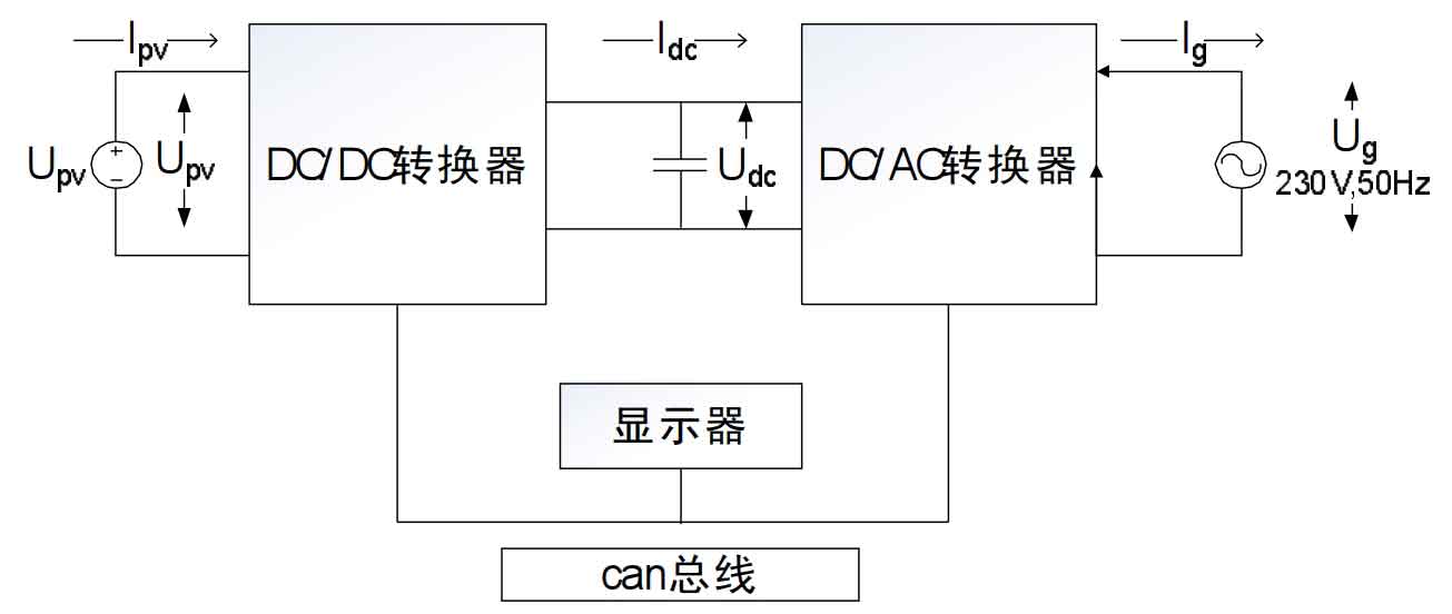
Generally speaking, DC/DC converters convert photoelectricity into controllable direct current, while DC/AC converters convert direct current into current and then transfer it to the power grid. This design and development provide conditions for better MPPT tracking. At the same time, when the solar inverter is connected to the power grid, the optimal current is controlled in the DC/AC converter to reduce harmonics. Unlike wind energy systems, solar systems do not require any mechanical or electronic interconnections to generate electrical power from sunlight. Photovoltaic (PV) cells are interconnected and form solar panels that directly capture sunlight and DC voltage. Generally speaking, each photovoltaic cell generates light from the captured sunlight
0.3~0.6 V DC voltage. In order to obtain the maximum DC voltage, a large number of photovoltaic cells are required to capture sunlight, and the DC output voltage from PV cells also depends on solar radiation. So in order to capture the maximum voltage at the radiation level, an effective MPPT algorithm should be proposed to periodically track the radiation level.
1. Analysis of MPPT control algorithm
1.1 Commonly used MPPT algorithm in photovoltaic power generation systems
Referring to the different types of MPPT control algorithms used in photovoltaic systems, the perturbation observation method (P&O), constant voltage (CVT) algorithm, and incremental conductance (INC) algorithm are commonly used. Later, the adaptive MPPT method for nonlinear radiation conditions was also proposed by many authors, who successively proposed fuzzy control methods. The authors who proposed this theory also implemented the method using field programmable gate arrays (FPGA). From previous studies, we have found that efficient dynamic MPPT control requires maximum output at the input terminals. This paper proposes a method of optimizing voltage from the MPPT controller using adaptive neurofuzzy control.
1.2 Adaptive Neural Fuzzy MPPT Algorithm
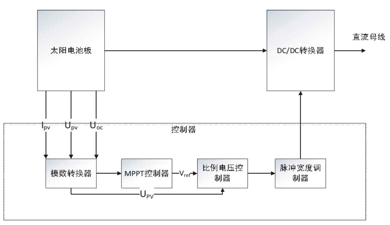
The hybrid learning control algorithm is used in adaptive neuro fuzzy systems to identify the parameters of a single member function. The block diagram of the PV module with the MPPT algorithm is shown in Figure 2. The control block receives input from the PV panel and calculates the duty cycle. Within the control block, the MPPT block calculates the reference voltage, and the proportional controller calculates the PWM duty cycle based on the panel voltage and reference voltage. Combining fuzzy neural network technology with MPPT blocks, using least squares and backpropagation descent methods to detect the parameters of member functions.
2. Simulation experiment research
2.1 Simulation Program Results and Analysis
This control algorithm has conducted simulation research on insulated gate bipolar transistors (IGBTs) based on solar inverters. In the simulation model, the input of the maximum power point tracking system includes the voltage (Upv), current (Ipv), and open circuit voltage (Uoc) of the photovoltaic panel. The intensity of sunlight is transmitted to the PV module in the form of square or sine waves. The photovoltaic module is responsible for measuring the given light intensity of the PV module. The output of the PV module is transmitted to the DC/DC converter, and the reference voltage of the DC link is also transmitted as input to the DC/DC converter. Sample the voltage and current of the PV module and provide them to the MPPT block and PV module, and then transmit them to the proportional voltage controller. The MPPT block calculates the reference voltage and sends it to the voltage controller, which calculates the duty cycle of the PWM signal based on the photovoltaic panel voltage. Calculate the tracking error and efficiency based on the formula:
Tracking efficiency=Ppv/Pmpp × 100%
Tracking error=(Pmpp Ppv)/Pmpp × 100%
In the formula: Ppv is the power of the photovoltaic panel; Pmpp is the power of the photovoltaic panel at the maximum power point.
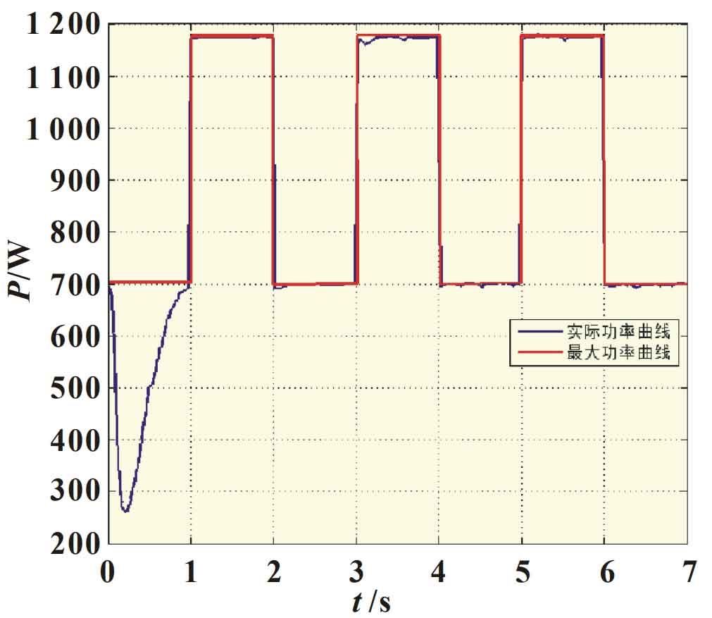
The Matlab function achieves a hybrid of two algorithms, whose output is the Vmpp value given by the proportional voltage controller, and simulates the DC/DC converter model. The square wave variation of 0.5 Hz under radiation of 500 and 800 W/m2 is shown in Figure 3. Assuming that the light intensity changes every second between 500 and 800 W/m2, although this situation is almost impossible, it can still relatively effectively track the efficiency of the actual maximum power point. In Figure 3, the steady-state value of 700 W is reached within 1 second after the power supply is momentarily reduced to 250 W. Despite fluctuations in voltage and current, the power remains constant and very close to the calculated maximum power.
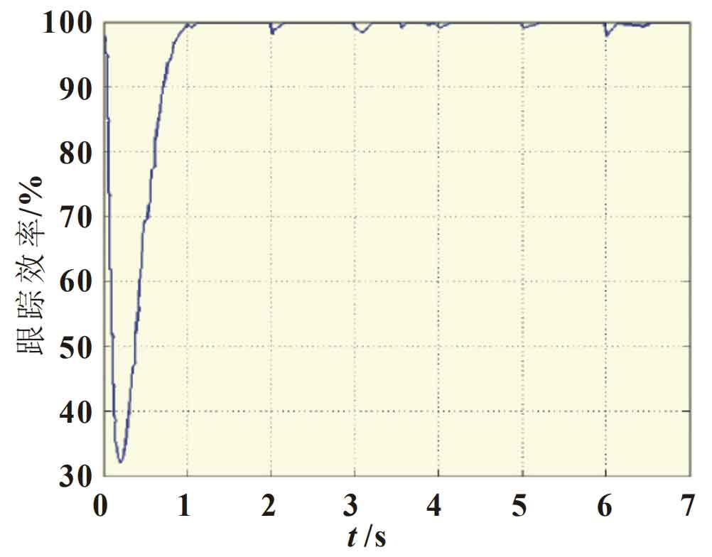
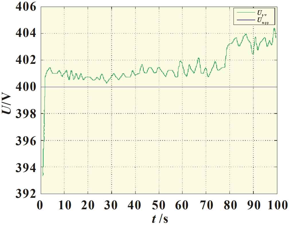
During the transition period, the generated power is less than the maximum value. Therefore, when the light intensity changes, the efficiency during the transition period will decrease. Figure 4 shows the tracking efficiency obtained from the dynamic model. During the startup process, the tracking efficiency decreased to 33% and increased to 99% after 1 second. Similarly, the tracking error was calculated at the corresponding point, and the actual photovoltaic power reached 67% and stabilized after 1 second. Under steady-state conditions, the tracking error is less than 1%. However, during the illumination period, the tracking efficiency decreased to 97%, and the tracking error increased to 3%, significantly affecting the efficiency of the solar inverter. The actual operating voltage and maximum power point tracking voltage under maximum illumination intensity are shown in Figure 5.
2.2 Experimental Results and Analysis
Design experiments were conducted on the specifications of the simulated solar inverter. The DC/DC converter experimental circuit is shown in Figure 6. The hardware of the solar inverter consists of a transistor based on a DC/DC converter, a DC side capacitor, a DC/AC converter, and an LCL filter. The main components of the experimental equipment include DC/DC boards, DC capacitors, DC/AC boards, and LCL filters. Divide the 6 kW DC/DC board into three 2 kW DC/DC boards for parallel connection, with the aim of optimizing the operation of the circuit board.
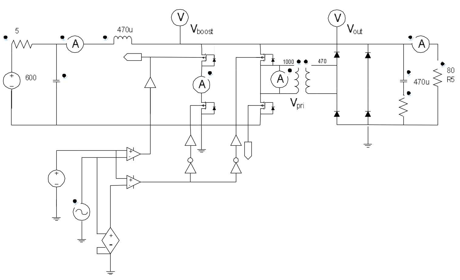
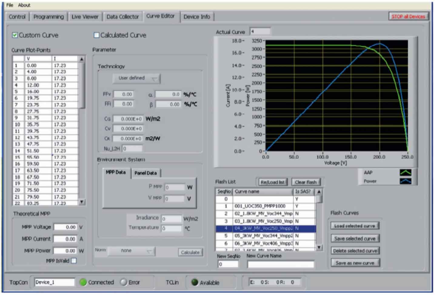
Based on the power availability of solar panels, the maximum power captured from DC/DC panels can reach 6 kW. The variation range of photovoltaic voltage is 180-400 V, which serves as the voltage of the DC bus capacitor. The input photovoltaic voltage is fed to the H-bridge power module with a front-end filter and boost section, and the input voltage is raised by the boost inductor. The power module consists of an H-bridge Mosfet, a current detection device, and a diode bridge rectifier. In the first cycle, all Mosfets in the H-bridge are connected to charge the boost inductor, and the voltage rises; When turning off, the diagonal Mosfet is turned off. Similarly, in the next cycle, after the boost inductor is charged, other Mosfets will shut down, and the output of the power module will be isolated by a transformer and fed to the solar inverter. The turn ratio of the transformer is 0.75, and the controller includes advanced peripherals, such as high-precision PWM output [8], to achieve an analog-to-digital converter for the control circuit. The analog-to-digital converter measures variables including photovoltaic output voltage and current, and then adjusts the DC/DC or DC/AC converter by changing the PWM duty cycle. In a single cycle, C2000 is used to read analog-to-digital converters and adjust PWM for real-time control. Figure 7 shows the PV and IV curves captured by the photovoltaic simulator at a given irradiance level of 500 W/m2.
The tracking efficiency at different power levels without changing the radiation value is shown in Table 1, which directly reflects the strengths of the MPPT algorithm proposed in this paper.
| Experiment number | 1 | 2 | 3 | 4 | 5 | 6 | 7 | 8 |
| Power/W | 5 | 10 | 20 | 25 | 30 | 50 | 75 | 100 |
| Efficiency/% | 100 | 99.58 | 99.72 | 99.32 | 99.75 | 99.79 | 99.21 | 99.43 |
3. Conclusion
This article proposes an efficient MPPT control algorithm using adaptive neural fuzzy technology. The algorithm was modeled and simulated in a Matlab/Simulink environment for a 6 kW rated single-phase solar inverter. The tracking efficiency was calculated based on the dynamic changes in radiation levels. The simulation results showed that the tracking efficiency reached 99%, confirming that the proposed control technology can capture the maximum tracking efficiency at the input end.